1
Programming Guide
COPYRIGHT
This manual is proprietary to SAMSUNG Electronics Co., Ltd. and is protected by copyright.
No information contained herein may be copied, translated, transcribed or duplicated for any
commercial purposes or disclosed to third parties in any form without the prior written consent
of SAMSUNG Electronics Co., Ltd.
TRADEMARKS
OfficeServ 500 is the trademark of SAMSUNG Electronics Co., Ltd.
Product names mentioned in this document may be trademarks and/or registered trademarks
of their respective companies.
Please read this guide before using the OfficeServ 500 system, and follow the instructions to use the OfficeServ
500 system safely and correctly.
This manual may be changed for the product improvement, standardization and other technical reasons without prior
notice.
For further information on the updated manual or have a question the content of manual, contact your Authorised
Samsung Reseller.
INTRODUCTION
Purpose
This guide is a programming description for OfficeServ 500 system users.
OfficeServ 500 allows you to utilize a digital phone to simply change the system
setup. Likewise, using a phone to change the system setup is called MMC(Man
Machine Communication) program.
This guide describes how to use a digital phone to use MMC.
When there are questions about OfficeServ 500 system or damage to the phone,
please call your Authorised Samsung Reseller.
Document Content and Organization
This programming guide is composed of a total of 2 chapters. Each chapter is
introduced as follows :
CHAPTER 1. Before Programming
This chapter describes things to know before starting MMC programming and about
the buttons of digital phone and cautions.
CHAPTER 2. MMC Programming
This chapter describes how to use each MMC program as it was listed.
© SAMSUNG Electronics Co., Ltd.
Page I
Introduction
OfficeServ 500 Programming Guide/Ed.00
Conventions
The following special paragraphs are used in this document to point out information
that must be read. This information may be set-off from the surrounding text, but is
always preceded by a bold title in capital letters.
WARNING
Indicates a potentially hazardous situation which if not avoided, could result in death
or serious injury.
CAUTION
Indicates a potentially hazardous situation which if not avoided, may result in minor or
moderate injury. It may also be used to alert against unsafe practices.
NOTE
Indicates additional information as a reference.
Console Screen Output
The lined box with Courier New font will be used to distinguish between
the main content and console output screen text.
Bold Courier New font will indicate the value entered by the operator on
the console screen
Reference
OfficeServ 500 Installation Guide
Introduces the installation related information for OfficeServ 500 system.
OfficeServ 500 Service Manual
Introduces circuit configuration of each section in OfficeServ 500 system, main
functions, parts list, troubleshooting, and disassembly diagram of main device.
DS-5012L Digital Phone Users Manual
This is a users manual for the Large LCD Digital Phone(DS-5012L) that can be used
by connecting to the OfficeServ 500 system.
Page II
© SAMSUNG Electronics Co., Ltd.
OfficeServ 500 Programming Guide/Ed.00
Introduction
ITP-5012L IP Phone Users Manual
This is a users manual for the Large LCD IP Phone that can be used by connecting to
the OfficeServ 500 system.
DS-5038D/5021D/5014D Digital Phone User Guide
This is a users manual for the 2 Line LCD Digital Phone(DS-5038D, DS-5012D,
DS-5014D) that can be used by connecting to the OfficeServ 500 system.
ITP-5021D/5014D IP Phone User Guide
This is a users manual for the 2 Line LCD IP Phone(ITP-5021D, ITP-5014D) that
can be used by connecting to the OfficeServ 500 system.
OfficeServ 500 Wireless LAN Service Manual
Introduces information needed to install the wireless device of the OfficeServ 500
system or for its maintenance.
WIP-5000M Phone User Guide
This is a users manual for WIP-5000M that is designed to use wireless LAN
provided from the OfficeServ 500 system.
The manuals for OfficeServ 500 Wireless LAN and WIP-5000M Phone will be
provided at the time of product release in later time.
Revision History
EDITION
DATE OF ISSUE
© SAMSUNG Electronics Co., Ltd.
REMARKS
Page III
Introduction
OfficeServ 500 Programming Guide/Ed.00
This page is intentionally left blank
Page IV
© SAMSUNG Electronics Co., Ltd.
SAFETY CONCERNS
SAFETY CONCERNS
For product safety and correct operation, the following information must be given to
the operator/user and shall be read before the installation and operation.
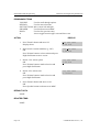
Symbols
Caution
Indication of a general caution
Restriction
Indication for prohibiting an action for a product
Instruction
Indication for commanding a specifically required action
© SAMSUNG Electronics Co., Ltd.
Page V
Safety Concerns
OfficeServ 500 Programming Guide/Ed.00
Caution
CAUTION
Caution
Digital Phone Volume Control
Program 807 Digital Phone Voice Quality Control seriously affects the system
credibility. Please call the reseller where you purchased the product to get an experts
advice.
System Passcode Change
When changing the system passcode using Program 900 System Program Delete,
please call the reseller where you purchased the product to get an experts advice.
Compliance with the National Version Standard
For the national version, OfficeServ50 is designed to comply with the standard of the
corresponding country. Therefore, in case the Program 812 Program the national
standard change needs to be used, please call the service company assigned by
Samsung to get an experts advice.
Page VI
© SAMSUNG Electronics Co., Ltd.
TABLE OF CONTENTS
INTRODUCTION
Purpose ...................................................................................................................................I
Document Content and Organization ......................................................................................I
Conventions............................................................................................................................II
Console Screen Output ..........................................................................................................II
Reference ...............................................................................................................................II
Revision History.....................................................................................................................III
SAFETY CONCERNS
Symbols ................................................................................................................................. V
Caution ................................................................................................................................. VI
CHAPTER 1. Before Programming
1
2
Introduction to Programming.......................................................................................... 1-1
1.1
Technician Level Program ......................................................................................... 1-1
1.2
1.3
Operator Level Program ............................................................................................ 1-1
Station Level Program ............................................................................................... 1-1
Phone Buttons .................................................................................................................. 1-2
2.1 DS-4000 Series phones ................................................................................................ 1-3
2.2
DS/ITP-5000D Series Phones........................................................................................ 1-4
3
Cautions in Programming................................................................................................ 1-6
4
Program List...................................................................................................................... 1-7
4.1 Station Level Programming ....................................................................................... 1-7
5
4.2
Operator Level Programming .................................................................................... 1-8
4.3
Technician Level Programming ............................................................................... 1-13
Overview of Programming Procedure.......................................................................... 1-15
© SAMSUNG Electronics Co., Ltd.
Page VII
Table of Contents
OfficeServ 500 Programming Guide/Ed.00
CHAPTER 2. MMC Programming
100 STATION LOCK ................................................................................................................. 2-2
101 CHANGE USER PASSCODE ............................................................................................ 2-3
102 CALL FORWARD............................................................................................................... 2-4
103 SET ANSWER MODE ........................................................................................................ 2-6
104 STATION NAME ................................................................................................................. 2-8
105 STATION SPEED DIAL .................................................................................................... 2-10
106 STATION SPEED DIAL NAME ........................................................................................ 2-12
107 KEY EXTENDER.............................................................................................................. 2-14
108 STATION STATUS............................................................................................................ 2-16
109 DATE DISPLAY ................................................................................................................ 2-18
110 STATION ON/OFF ............................................................................................................ 2-20
111 PHONE RING TONE ........................................................................................................ 2-22
112 ALARM REMINDER CLOCK........................................................................................... 2-23
113 VIEW MEMO NUMBER.................................................................................................... 2-25
114 PHONE VOLUME............................................................................................................. 2-27
115 SET PROGRAMMED MESSAGE .................................................................................... 2-29
116 ALARM AND MESSAGE ................................................................................................. 2-30
117 EDIT TEXT MESSAGE .................................................................................................... 2-32
118 CONFERENCE GROUP .................................................................................................. 2-34
119 CALLER ID DISPLAY ...................................................................................................... 2-36
120 LARGE LCD OPTION ...................................................................................................... 2-38
121 PHONE LANGUAGE ....................................................................................................... 2-40
122 NEWS DISPLAY SPEED.................................................................................................. 2-42
125 EXECUTIVE STATE ......................................................................................................... 2-43
200 OPEN CUSTOMER PROGRAMMING............................................................................. 2-45
201 CHANGE CUSTOMER PASSCODE................................................................................ 2-47
202 CHANGE FEATURE PASSCODE ................................................................................... 2-48
203 ASSIGN UA DEVICE........................................................................................................ 2-50
204 COMMON BELL CONTROL............................................................................................ 2-51
205 ASSIGN LOUD BELL ...................................................................................................... 2-52
Page VIII
© SAMSUNG Electronics Co., Ltd.
OfficeServ 500 Programming Guide/Ed.00
Table of Contents
206 BARGE-IN TYPE ............................................................................................................. 2-53
207 ASSIGN VM/AA PORT .................................................................................................... 2-54
208 ASSIGN RING TYPE ....................................................................................................... 2-56
209 ASSIGN ADD-ON MODULE ............................................................................................ 2-57
210 CUSTOMER ON/OFF PER TENANT .............................................................................. 2-58
211 DOOR RING ASSIGNMENT ............................................................................................ 2-62
214 DISA ALARM RINGING STATION................................................................................... 2-63
215 VOICE DIALLER OPTIONS............................................................................................. 2-64
216 VOICE DIALLER ASSIGNMENTS .................................................................................. 2-65
217 TRAFFIC REPORT OPTION ........................................................................................... 2-67
220 ISDN SERVICE TYPE ...................................................................................................... 2-69
221 EXTENSION TYPE .......................................................................................................... 2-70
222 FAX PAIR ......................................................................................................................... 2-72
224 WAKE-UP ANNOUNCEMENT......................................................................................... 2-73
300 CUSTOMER ON/OFF PER STATION.............................................................................. 2-75
301 ASSIGN STATION COS................................................................................................... 2-77
302 PICKUP GROUPS............................................................................................................ 2-79
303 ASSIGN BOSS/SECRETARY.......................................................................................... 2-80
304 ASSIGN EXTENSION/TRUNK USE ................................................................................ 2-82
305 ASSIGN FORCED CODE ................................................................................................ 2-84
306 HOT LINE/OFF HOOK SELECTION ............................................................................... 2-86
308 ASSIGN BACKGROUND MUSIC SOURCE ................................................................... 2-87
309 ASSIGN STATION MOH SOURCE.................................................................................. 2-89
310 LCR CLASS OF SERVICE .............................................................................................. 2-91
312 ALLOW CALLER ID ........................................................................................................ 2-92
314 CONFIRM OUTGOING CALL.......................................................................................... 2-93
315 CUSTOMER SET RELOCATION .................................................................................... 2-94
316 COPY STN/TRK USE....................................................................................................... 2-97
317 ASSIGN STATION/STATION USE................................................................................... 2-98
318 DISTINCTIVE RINGING................................................................................................. 2-100
319 BRANCH GROUP .......................................................................................................... 2-102
© SAMSUNG Electronics Co., Ltd.
Page IX
Table of Contents
OfficeServ 500 Programming Guide/Ed.00
320 PRESET FWD NO ANSWER......................................................................................... 2-103
323 CALLING PARTY NUMBER .......................................................................................... 2-105
400 CUSTOMER ON/OFF PER TRUNK .............................................................................. 2-107
401 Trunk Line/PBX LINE .................................................................................................... 2-109
402 TRUNK DIAL TYPE ....................................................................................................... 2-110
403 TRUNK TOLL CLASS.....................................................................................................2-111
404 TRUNK NAME................................................................................................................ 2-113
405 TRUNK CO TEL NUMBER ............................................................................................ 2-115
406 TRUNK RING ASSIGNMENT ........................................................................................ 2-117
407 FORCED TRUNK RELEASE ......................................................................................... 2-119
408 ASSIGN TRUNK MOH SOURCE .................................................................................. 2-120
409 TRUNK STATUS READ ................................................................................................. 2-122
410 ASSIGN DISA TRUNK ................................................................................................... 2-124
411 ASSIGN E1 SIGNAL TYPE............................................................................................ 2-126
412 ASSIGN TRUNK SIGNAL.............................................................................................. 2-128
413 VMS CALL TYPE ........................................................................................................... 2-129
414 PRS SIGNAL .................................................................................................................. 2-130
415 REPORT TRUNK ABANDON DATA ............................................................................. 2-132
416 ASSIGN E & M/DID RINGDOWN .................................................................................. 2-134
417 E1/PRI CRC4 OPTION................................................................................................... 2-136
418 BRI AND PRI CARD RESTART..................................................................................... 2-137
419 BRI OPTIONS ................................................................................................................ 2-138
420 PRI OPTIONS................................................................................................................. 2-142
421 MSN DIGIT ..................................................................................................................... 2-144
422 TRUNK COS .................................................................................................................. 2-146
423 S/T MODE ...................................................................................................................... 2-148
424 BRI S0 MAPPING .......................................................................................................... 2-149
425 ASSIGN CALLER ID TRUNKS...................................................................................... 2-150
426 TRUNK GAIN CONTROL .............................................................................................. 2-152
428 ASSIGN TRUNK/TRUNK USE ...................................................................................... 2-153
433 COST RATE ................................................................................................................... 2-155
Page X
© SAMSUNG Electronics Co., Ltd.
OfficeServ 500 Programming Guide/Ed.00
Table of Contents
434 CONNECTION STATUS................................................................................................. 2-156
436 TRUNK TMC GAIN ........................................................................................................ 2-159
500 SYSTEM-WIDE COUNTERS ......................................................................................... 2-161
501 SYSTEM TIMERS .......................................................................................................... 2-163
502 STATION-WIDE TIMERS ............................................................................................... 2-169
503 TRUNK-WIDE TIMER .................................................................................................... 2-171
504 PULSE MAKE/BREAK RATIO ...................................................................................... 2-173
505 ASSIGN DATE AND TIME ............................................................................................. 2-174
506 TONE CADENCE ........................................................................................................... 2-175
507 ASSIGN RING PLAN TIME ........................................................................................... 2-177
508 CALL COST ................................................................................................................... 2-179
510 SLI RING CADENCE ..................................................................................................... 2-181
511 MSG WAITING LAMP CADENCE ................................................................................. 2-183
512 HOLIDAY ASSIGNMENT ............................................................................................... 2-184
513 HOTEL TIMER ............................................................................................................... 2-185
514 TONE SOURCE ............................................................................................................. 2-186
515 ASSIGN DAYLIGHT SAVING DATE.............................................................................. 2-187
600 ASSIGN OPERATOR GROUP ...................................................................................... 2-188
601 ASSIGN STATION GROUP ........................................................................................... 2-189
602 STATION GROUP NAME............................................................................................... 2-193
603 ASSIGN TRUNK GROUP .............................................................................................. 2-195
604 ASSIGN STATION TO PAGE ZONE.............................................................................. 2-197
605 ASSIGN EXTERNAL PAGE ZONE ............................................................................... 2-198
606 ASSIGN SPEED BLOCK............................................................................................... 2-199
607 UCD OPTIONS............................................................................................................... 2-201
608 ASSIGN REVIEW BLOCK............................................................................................. 2-206
609 CALL LOG BLOCK........................................................................................................ 2-207
611 ALLOW TEXT MESSAGING ......................................................................................... 2-208
612 ALLOW GROUP CONFERENCE .................................................................................. 2-209
614 STATION/TRUNK USE GROUP .................................................................................... 2-210
615 MGI GROUP................................................................................................................... 2-212
© SAMSUNG Electronics Co., Ltd.
Page XI
Table of Contents
OfficeServ 500 Programming Guide/Ed.00
616 MGI USER ...................................................................................................................... 2-214
700 COPY COS CONTENTS ................................................................................................ 2-216
701 ASSIGN COS CONTENTS ............................................................................................ 2-217
702 TOLL DENY TABLE ....................................................................................................... 2-221
703 TOLL ALLOWANCE TABLE.......................................................................................... 2-223
704 ASSIGN WILD CHARACTER ........................................................................................ 2-225
705 ASSIGN SYSTEM SPEED DIAL ................................................................................... 2-226
706 SYSTEM SPEED DIAL BY NAME................................................................................. 2-228
707 AUTHORIZATION CODE............................................................................................... 2-230
708 ACCOUNT CODE .......................................................................................................... 2-231
709 TOLL PASS CODE/SPECIAL CODE TABLE................................................................ 2-232
710 LCR DIGIT TABLE ......................................................................................................... 2-234
711 LCR TIME TABLE .......................................................................................................... 2-235
712 LCR ROUTE TABLE ...................................................................................................... 2-236
713 LCR MODIFY DIGIT TABLE .......................................................................................... 2-238
714 DID NUMBER AND NAME TRANSLATION.................................................................. 2-240
715 PROGRAMMED STATION MESSAGE.......................................................................... 2-244
716 UK LCR OPTIONS ......................................................................................................... 2-246
717 UCD AGENT ID .............................................................................................................. 2-248
718 MY AREA CODE ............................................................................................................ 2-249
719 IDLE DISPLAY ............................................................................................................... 2-250
720 COPY KEY PROGRAMMING ........................................................................................ 2-252
721 SAVE STATION KEY PROGRAMMING ........................................................................ 2-253
722 STATION KEY PROGRAMMING................................................................................... 2-254
723 SYSTEM KEY PROGRAMMING ................................................................................... 2-259
724 DIAL NUMBERING PLAN ............................................................................................. 2-261
725 SMDR OPTIONS ............................................................................................................ 2-267
726 VM/AA OPTIONS ........................................................................................................... 2-270
727 SYSTEM VERSION DISPLAY ....................................................................................... 2-276
728 CID TRANSLATION TABLE .......................................................................................... 2-277
730 AA RECORD GAIN ........................................................................................................ 2-279
Page XII
© SAMSUNG Electronics Co., Ltd.
OfficeServ 500 Programming Guide/Ed.00
Table of Contents
731 AA RAM CLEAR ............................................................................................................ 2-280
732 AA TRANSLATION TABLE ........................................................................................... 2-281
733 AA PLAN TABLE ........................................................................................................... 2-285
734 AUTO ATTENDANT MESSAGE MATCH ...................................................................... 2-290
735 AA USE TABLE ............................................................................................................. 2-292
736 ASSIGN AA MOH........................................................................................................... 2-294
737 DECT SYSTEM CODE................................................................................................... 2-295
738 DECT CLEAR REGISTRATION .................................................................................... 2-297
740 STATION PAIR ............................................................................................................... 2-299
741 DBS RESTART .............................................................................................................. 2-300
742 BSI STATUS ................................................................................................................... 2-302
743 DBS STATUS ................................................................................................................. 2-303
744 DECT REGISTRATION ON/OFF ................................................................................... 2-304
745 BSI RF CARRIER .......................................................................................................... 2-305
746 COSTING DIAL PLAN ................................................................................................... 2-306
747 RATE CALCULATION TABLE....................................................................................... 2-308
750 VM CARD RESTART ..................................................................................................... 2-310
751 ASSIGN MAILBOX ........................................................................................................ 2-312
752 AUTO RECORD ............................................................................................................. 2-314
753 WARNING DESTINATION ............................................................................................. 2-316
754 VM HALT ........................................................................................................................ 2-317
755 VM ALARM .................................................................................................................... 2-318
756 ASSIGN VM MOH .......................................................................................................... 2-319
757 VM IN/OUT ..................................................................................................................... 2-321
758 VM DAY/NIGHT .............................................................................................................. 2-322
760 ITEM COST TABLE ....................................................................................................... 2-323
761 TAX RATE SETUP ......................................................................................................... 2-326
762 ROOM COST RATE ....................................................................................................... 2-329
800 ENABLE TECHNICIAN PROGRAM.............................................................................. 2-330
801 CHANGE TECHNICIAN PASSCODE............................................................................ 2-332
802 CUSTOMER ACCESS MMC NUMBER......................................................................... 2-333
© SAMSUNG Electronics Co., Ltd.
Page XIII
Table of Contents
OfficeServ 500 Programming Guide/Ed.00
803 ASSIGN TENANT GROUP ............................................................................................ 2-334
804 SYSTEM I/O PARAMETER............................................................................................ 2-335
805 LEVEL AND GAIN.......................................................................................................... 2-338
806 CARD PRE-INSTALL ..................................................................................................... 2-341
807 PHONE VOLUME CONTROL........................................................................................ 2-343
809 SYSTEM MMC SANGUAGE ......................................................................................... 2-346
810 HALT PROCESSING ..................................................................................................... 2-347
811 RESET SYSTEM ............................................................................................................ 2-348
812 SET COUNTRY CODE................................................................................................... 2-350
813 HOTEL OPERATION...................................................................................................... 2-351
815 CUSTOMER DATABASE COPY ................................................................................... 2-352
816 CONFERENCE GAIN..................................................................................................... 2-354
818 PROGRAM DOWNLOAD .............................................................................................. 2-356
819 SMART MEDIA FILE CONTROL................................................................................... 2-357
820 ASSIGN SYSTEM LINK ID ............................................................................................ 2-358
821 ASSIGN NETWORK TRUNK......................................................................................... 2-359
822 SET VIRTUAL EXTENSION TYPE ................................................................................ 2-360
823 ASSIGN NETWORK COS.............................................................................................. 2-362
824 NETWORK DIAL TRANSLATION ................................................................................. 2-364
825 ASSIGN NETWORKING OPTION ................................................................................. 2-366
826 ASSIGN SYSTEM REFERENCE CLOCK ..................................................................... 2-368
829 LAN PRINTER PARAMETER ........................................................................................ 2-369
830 ETHERNET PARAMETERS .......................................................................................... 2-371
831 MGI PARAMETERS ....................................................................................................... 2-374
832 VOIP ACCESS CODE .................................................................................................... 2-376
833 VoIP IP TABLE ............................................................................................................... 2-378
834 H.323 OPTIONS ............................................................................................................. 2-380
835 MGI DSP OPTIONS ....................................................................................................... 2-382
836 H.323 GK OPTIONS....................................................................................................... 2-385
837 SIP OPTIONS ................................................................................................................. 2-387
840 IP PHONE INFOMATION ............................................................................................... 2-390
Page XIV
© SAMSUNG Electronics Co., Ltd.
OfficeServ 500 Programming Guide/Ed.00
Table of Contents
841 SYSTEM IP OPTIONS ................................................................................................... 2-393
850 SYSTEM RESOURCE DISPLAY ................................................................................... 2-396
851 ALARM REPORTING .................................................................................................... 2-397
852 SYSTEM ALARM ASSIGNMENTS................................................................................ 2-399
853 MAINTENANCE BUSY .................................................................................................. 2-406
854 DIAGNOSTIC TIME ....................................................................................................... 2-408
855 SYSTEM OPTIONS........................................................................................................ 2-409
856 TECH PROGRAMMING LOGS ..................................................................................... 2-411
858 ASSIGN SYSTEM EMERGENCY ALARM.................................................................... 2-412
859 HARDWARE VERSION DISPLAY ................................................................................. 2-413
860 UCD STATUS SERVICE ................................................................................................ 2-415
861 SYSTEM OPTIONS........................................................................................................ 2-416
890 INITIALISE PORT .......................................................................................................... 2-418
LIST OF FIGURES
Figure 1.1
DS-4028E Phone............................................................................................ 1-3
Figure 1.2
Figure 1.3
DS-5038D phone ............................................................................................ 1-4
DS-5021D/ITP-5021D phone ......................................................................... 1-4
Figure 1.4
DS-5014D/ITP-5014D phone ......................................................................... 1-5
LIST OF TABLES
Table 2.1
CUSTOMER SET RELOCATION ALLOW TABLE ......................................... 2-95
© SAMSUNG Electronics Co., Ltd.
Page XV
Table of Contents
OfficeServ 500 Programming Guide/Ed.00
This page is intentionally left blank
Page XVI
© SAMSUNG Electronics Co., Ltd.
CHAPTER 1
Before Programming
In this chapter, the things to know before you start MMC programming, and the
phone buttons and cautions will be discussed.
1
Introduction to Programming
The MMC program means the changes on the data that is used for the system
operation program. There are 3 levels of MMC programming, such as technician,
operator, and station levels. According to the programming level, the station can
program or cannot program the data change. The technician level programming and
the operator level programming require a passcode for each level while the station
level programming does not require a passcode.
1.1
Technician Level Program
This level is allowed to program every level of program.
This level of programming can be done on every phone within the system, but it can
be done for only one phone at a time.
1.2
Operator Level Program
An technician can do programming within the range set by the MMC 802-Operator
Program Range Setting.
Programming is allowed for any phone within the tenant group, but it can be done for
only one phone at a time.
1.3
Station Level Program
Programming can be done for only station level programs.
© SAMSUNG Electronics Co., Ltd.
Page 1-1
CHAPTER 1. Before Programming
2
OfficeServ 500 Programming Guide/Ed.00
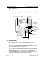
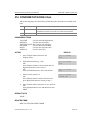
Phone Buttons
There are several phones that are allowed for MMC programming ; DCS Euro
phones (24B/12B/6B LCD), DS-4000 series phones(DS-4028E, DS-4018E, DS4008E), DS-5000D series phone(DS-5038D, DS-5021D, DS-5014D) and ITP-5000D
series phone(ITP-5021D, ITP-5014D)
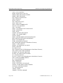
VOLUME CONTROL BUTTONS
Volume control for handset,
Ring, speaker, ect
SOFT BUTTONS(3)
Uesd activate
Features via the display
SCROLL BUTTON
Uesd to select start menu and
scroll through display options
SCROLL
VOLUME
PROGRAMMABLE
BUTTONS
With tri-coloured LEDs :
24B keyset has 16 Buttons
12B keyset has 8 Buttons
REDIAL MEMORY
REDIAL BUTTON
DND SPEAKER
MEMORY BUTTON
DO NOT DISTURB BUTTON
SPEAKER BUTTON
TRSF RECALL
HOLD
SPEAKER
For hands-free operation.
Used in place of handset
ANS/RLS
PROGRAMMABLE BUTTONS
With red LEDs :
24B has 8 Buttons
12B has 4 Buttons
MICROPHONE
PULLOUT
DIRECTORY TRAY
TRANSFER BUTTON
HOLD BUTTON
ANSWER/RELEASE
BUTTON
RECALL BUTTON
2.1
DCS Euro phones
The following figure shows the shape of 24B/12B LCD DCS Euro phone.
24B LCD phone has 24 programmable buttons: left column is numbered 1-12 from
the top; right column is numbered 13-24 from the top.
12B LCD phone has 12 programmable buttons numbered 1-12 from top to bottom.
By default : Button 1 and 2 are set as CALL buttons. CALL buttons flash for
incoming calls. Button 24(24B LCD phone) or button 12(12B LCD phone) is set as
MSG button. The MSG button flashes to indicate message waiting.
Page 1-2
© SAMSUNG Electronics Co., Ltd.
OfficeServ 500 Programming Guide/Ed.00
CHAPTER 1. Before Programming
ANS/RLS : Answer and release calls
HOLD : Hold Calls
MEMORY : Speed dialing button
REDIAL : Last number redial
TRSF : Transfer current call(or enter MMC programming mode)
SPEKER : Switch on speakerphone
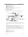
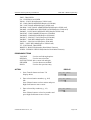
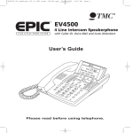
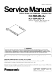
2.2
DS-4000 Series phones
The following figure shows the shape of DS-4028E phone among DS-4000 series
phones.
LCD Display
Left Soft Button
Right Soft Button
A Button
B Button
Dial Buttons
Transfer Button
Speaker Button
ANS/RLS Button
Volume Buttons
Hold Button
Figure 1.1 DS-4028E Phone
Among 3 Soft buttons, the first one is called the Left Soft button, which is used to
save the modified data or to move the cursor inside the LCD display in the left
direction.
Among 3 Soft buttons, the third one is called the Right Soft button, which is used to
save the modified data or to move the cursor in the right direction.
Among 8 programmable buttons, the first 6 programmable buttons are assigned as
A~F to carry out specific functions or usage while programming. Generally, these
buttons perform specific functions that you set for each corresponding button.
When MMC programming, other functions programmed on the programmable buttons
are as follows :
VOLUME : Search the selected items.
KEYPAD : Confirm the status
SOFT BUTTONS : Move the cursor
© SAMSUNG Electronics Co., Ltd.
Page 1-3
CHAPTER 1. Before Programming
OfficeServ 500 Programming Guide/Ed.00
SPEAKER : Save data and proceed to the next program
HOLD : Erase the previously entered item
A : Select either a capital letter or small letter
B : Select either a Korean character or English character
TRANSFER : Enter the programming code
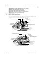
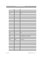
2.3
DS/ITP-5000D Series Phones
There are several DS/ITP-5000D series phones, such as DS-5038D, DS-5021D, DS5014D, ITP-5021D, ITP-5014D as shown in the figures below :
LCD Display
Programmable Buttons(21)
Soft buttons
Scroll Button
Telephone Status Indicator
Volume Buttons
Programmable Buttons(17)
Redial Button
Dial Buttons
Microphone
Speaker Button
Conference Button
Transfer Button
Hold Button
Figure 1.2 DS-5038D phone
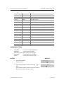
Programmable Buttons(21)
LCD Display
Soft buttons
Scroll Button
Telephone Status Indicator
Volume Buttons
Redial Button
Navigation Buttons
Dial Buttons
Microphone
Speaker Button
Conference Button
Transfer Button
Hold Button
Figure 1.3 DS-5021D/ITP-5021D phone
Page 1-4
© SAMSUNG Electronics Co., Ltd.
OfficeServ 500 Programming Guide/Ed.00
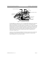
Programmable Buttons(14)
CHAPTER 1. Before Programming
LCD Display
Soft buttons
Scroll
Telephone Status Indicator
Volume Buttons
Redial Button
Navigation Button
Dial Buttons
Microphone
Speaker Button
Hold Button
Conference Button
Transfer Button
Figure 1.4 DS-5014D/ITP-5014D phone
The DS-5000D series phones have 38/21/14 programmable buttons that a station can
register any functions he/she wants to use. Also, there are several other function
buttons: the dial buttons, the volume button for controlling a voice volume, the redial
button that allows to redial the latest phone number, the conference button that can be
used during the conference, the transfer button that is used to transfer a call received
during a phone conversation to another station, the hold button to hold a call for a
while, the speaker button, and the navigation buttons that are designed for the
convenience of phone users.
And, there is the LCD display that displays the station status and various other kinds
of information. With three colors like red, green, and yellow, the station status
indicator displays the current status of station.
© SAMSUNG Electronics Co., Ltd.
Page 1-5
CHAPTER 1. Before Programming
3
OfficeServ 500 Programming Guide/Ed.00
Cautions in Programming
Programming can be done while the handset is placed on the phone at a idle state.
Programming can be done on any phone.
Programming can be done only on the phone, not on normal phone.
If the phone does not have the LCD display, press the numbers using the dial
buttons as instructed by the programming guide, without using the volume
buttons. However, if the phone does not have Soft buttons, certain programming
cannot be done. Therefore, only the station level programming is allowed on the
phone that does not have the LCD display.
If the LCD displays an INVALID DATA message while programming, this
means that the entered data is invalid. Enter the correct data again.
The content of the displayed message for each step shows the status after each
step is executed.
If no key is pressed for a certain period of time during programming
(Key program end time, default is 60 seconds), it becomes a idle state from
programming mode.
If the phone is off hook while programming, it becomes a dial state from
programming mode.
Before the modified data is confirmed by pressing [Left Soft] button or [Right
Soft] button, the [Speaker] or [Transfer] button is pressed to make it at a idle state
or the phone is unplugged. In this case, the data entered up to that time will be
automatically saved as the data displayed on the LCD.
Page 1-6
© SAMSUNG Electronics Co., Ltd.
OfficeServ 500 Programming Guide/Ed.00
4
CHAPTER 1. Before Programming
Program List
The MMC program can be divided into programmable one and non-programmable
one. The programmable MMC is classified into 3 levels, such as technician, operator,
and station level. In this section, the programmable MMC for each level will be
introduced.
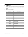
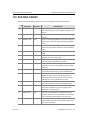
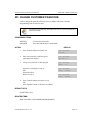
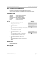
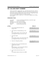
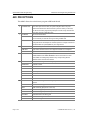
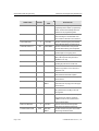
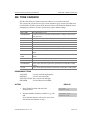
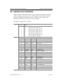
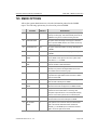
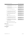
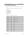
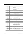
4.1
Station Level Programming
MMC Program No.
Program Description
MMC : 100
STATION LOCK
MMC : 101
CHANGE USER PASSCODE
MMC : 102
CALL FORWARD
MMC : 103
SET ANSWER MODE
MMC : 104
STATION NAME
MMC : 105
STATION SPEED DIAL
MMC : 106
STATION SPEED DIAL NAME
MMC : 107
KEY EXTENDER
MMC : 108
STATION STATUS
MMC : 109
DATE DISPLAY
MMC : 110
STATION ON/OFF
MMC : 111
PHONE RING TONE
MMC : 112
ALARM REMINDER CLOCK
MMC : 113
VIEW MEMO NUMBER
MMC : 114
PHONE VOLUME
MMC : 115
SET PROGRAMMED MESSAGE
MMC : 116
ALARM AND MESSAGE
MMC : 117
EDIT TEXT MESSAGE
MMC : 118
CONFERENCE GROUP
MMC : 119
CALLER ID DISPLAY
MMC : 120
LARGE LCD OPTION
MMC : 121
PHONE LANGUAGE
MMC : 122
NEWS DISPLAY SPEED
MMC : 125
EXECUTIVE STATE
© SAMSUNG Electronics Co., Ltd.
Page 1-7
CHAPTER 1. Before Programming
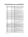
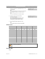
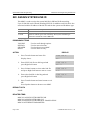
4.2
OfficeServ 500 Programming Guide/Ed.00
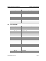
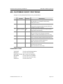
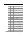
Operator Level Programming
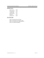
4.2.1 System Related MMC
MMC Program No.
Program Description
MMC : 200
OPEN CUSTOMER PROGRAMMING
MMC : 201
CHANGE CUSTOMER PASSCODE
MMC : 202
CHANGE FEATURE PASSCODE
MMC : 203
ASSIGN UA DEVICE
MMC : 204
COMMON BELL CONTROL
MMC : 205
ASSIGN LOUD BELL
MMC : 206
BARGE-IN TYPE
MMC : 207
ASSIGN VM/AA PORT
MMC : 208
ASSIGN RING TYPE
MMC : 209
ASSIGN ADD-ON MODULE
MMC : 210
CUSTOMER ON/OFF PER TENANT
MMC : 211
DOOR RING ASSIGNMENT
MMC : 214
DISA ALARM RINGING STATION
MMC : 215
VOICE DIALLER OPTIONS
MMC : 216
VOICE DIALLER ASSIGNMENTS
MMC : 217
TRAFFIC REPORT OPTION
MMC : 220
ISDN SERVICE TYPE
MMC : 221
EXTENSION TYPE
MMC : 222
FAX PAIR
MMC : 224
WAKE-UP ANNOUNCEMENT
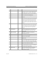
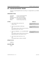
4.2.2 Station Related MMC
MMC Program No.
Page 1-8
Program Description
MMC : 300
CUSTOMER ON/OFF PER STATION
MMC : 301
ASSIGN STATION COS
MMC : 302
PICKUP GROUPS
MMC : 303
ASSIGN BOSS/SECRETARY
MMC : 304
ASSIGN EXTENSION/TRUNK USE
MMC : 305
ASSIGN FORCED CODE
MMC : 306
HOT LINE/OFF HOOK SELECTION
MMC : 308
ASSIGN BACKGROUND MUSIC SOURCE
MMC : 309
ASSIGN STATION MOH SOURCE
© SAMSUNG Electronics Co., Ltd.
OfficeServ 500 Programming Guide/Ed.00
CHAPTER 1. Before Programming
MMC Program No.
Program Description
MMC : 310
LCR CLASS OF SERVICE
MMC : 312
ALLOW CALLER ID
MMC : 314
CONFIRM OUTGOING CALL
MMC : 315
CUSTOMER SET RELOCATION
MMC : 316
COPY STN/TRK USE
MMC : 317
ASSIGN STATION/STATION USE
MMC : 318
DISTINCTIVE RINGING
MMC : 319
BRANCH GROUP
MMC : 320
PRESET FWD NO ANSWER
MMC : 323
CALLING PARTY NUMBER
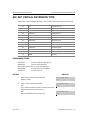
4.2.3 Trunk Related MMC
MMC Program No.
Program Description
MMC : 400
CUSTOMER ON/OFF PER TRUNK
MMC : 401
Trunk Line/PBX LINE
MMC : 402
TRUNK DIAL TYPE
MMC : 403
TRUNK TOLL CLASS
MMC : 404
TRUNK NAME
MMC : 405
TRUNK CO TEL NUMBER
MMC : 406
TRUNK RING ASSIGNMENT
MMC : 407
FORCED TRUNK RELEASE
MMC : 408
ASSIGN TRUNK MOH SOURCE
MMC : 409
TRUNK STATUS READ
MMC : 410
ASSIGN DISA TRUNK
MMC : 411
ASSIGN E1 SIGNAL TYPE
MMC : 412
ASSIGN TRUNK SIGNAL
MMC : 413
VMS CALL TYPE
MMC : 414
PRS SIGNAL
MMC : 415
REPORT TRUNK ABANDON DATA
MMC : 416
ASSIGN E&M/DID RINGDOWN
MMC : 417
E1/PRI CRC4 OPTION
MMC : 418
BRI AND PRI CARD RESTART
MMC : 419
BRI OPTIONS
MMC : 420
PRI OPTIONS
© SAMSUNG Electronics Co., Ltd.
Page 1-9
CHAPTER 1. Before Programming
OfficeServ 500 Programming Guide/Ed.00
MMC Program No.
Program Description
MMC : 421
MSN DIGIT
MMC : 422
TRUNK COS
MMC : 423
S/T MODE
MMC : 424
BRI S0 MAPPING
MMC : 425
ASSIGN CALLER ID TRUNKS
MMC : 426
TRUNK GAIN CONTROL
MMC : 428
ASSIGN TRUNK/TRUNK USE
MMC : 433
COST RATE
MMC : 434
CONNECTION STATUS
MMC : 436
TRUNK TMC GAIN
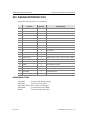
4.2.4 Timer and Tone Related MMC
MMC Program No.
Page 1-10
Program Description
MMC : 500
SYSTEM-WIDE COUNTERS
MMC : 501
SYSTEM TIMERS
MMC : 502
STATION-WIDE TIMERS
MMC : 503
TRUNK-WIDE TIMER
MMC : 504
PULSE MAKE/BREAK RATIO
MMC : 505
ASSIGN DATE AND TIME
MMC : 506
TONE CADENCE
MMC : 507
ASSIGN RING PLAN TIME
MMC : 508
CALL COST
MMC : 510
SLI RING CADENCE
MMC : 511
MSG WAITING LAMP CADENCE
MMC : 512
HOLIDAY ASSIGNMENT
MMC : 513
HOTEL TIMER
MMC : 514
TONE SOURCE
MMC : 515
ASSIGN DAYLIGHT SAVING DATE
© SAMSUNG Electronics Co., Ltd.
OfficeServ 500 Programming Guide/Ed.00
CHAPTER 1. Before Programming
4.2.5 Group Related MMC
MMC Program No.
Program Description
MMC : 600
ASSIGN OPERATOR GROUP
MMC : 601
ASSIGN STATION GROUP
MMC : 602
STATION GROUP NAME
MMC : 603
ASSIGN TRUNK GROUP
MMC : 604
ASSIGN STATION TO PAGE ZONE
MMC : 605
ASSIGN EXTERNAL PAGE ZONE
MMC : 606
ASSIGN SPEED BLOCK
MMC : 607
UCD OPTIONS
MMC : 608
ASSIGN REVIEW BLOCK
MMC : 609
CALL LOG BLOCK
MMC : 611
ALLOW TEXT MESSAGING
MMC : 612
ALLOW GROUP CONFERENCE
MMC : 614
STATION/TRUNK USE GROUP
MMC : 615
MGI GROUP
MMC : 616
MGI USER
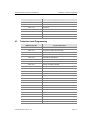
4.2.6 Tables, Codes, AA, DECT and VM MMC
MMC Program No.
Program Description
MMC : 700
COPY COS CONTENTS
MMC : 701
ASSIGN COS CONTENTS
MMC : 702
TOLL DENY TABLE
MMC : 703
TOLL ALLOWANCE TABLE
MMC : 704
ASSIGN WILD CHARACTER
MMC : 705
ASSIGN SYSTEM SPEED DIAL
MMC : 706
SYSTEM SPEED DIAL BY NAME
MMC : 707
AUTHORIZATION CODE
MMC : 708
ACCOUNT CODE
MMC : 709
TOLL PASS CODE/SPECIAL CODE TABLE
MMC : 710
LCR DIGIT TABLE
MMC : 711
LCR TIME TABLE
MMC : 712
LCR ROUTE TABLE
MMC : 713
LCR MODIFY DIGIT TABLE
MMC : 714
DID NUMBER AND NAME TRANSLATION
MMC : 715
PROGRAMMED STATION MESSAGE
© SAMSUNG Electronics Co., Ltd.
Page 1-11
CHAPTER 1. Before Programming
OfficeServ 500 Programming Guide/Ed.00
MMC Program No.
Page 1-12
Program Description
MMC : 716
UK LCR OPTIONS
MMC : 717
UCD AGENT ID
MMC : 718
MY AREA CODE
MMC : 719
IDLE DISPLAY
MMC : 720
COPY KEY PROGRAMMING
MMC : 721
SAVE STATION KEY PROGRAMMING
MMC : 722
STATION KEY PROGRAMMING
MMC : 723
SYSTEM KEY PROGRAMMING
MMC : 724
DIAL NUMBERING PLAN
MMC : 725
SMDR OPTIONS
MMC : 726
VM/AA OPTIONS
MMC : 727
SYSTEM VERSION DISPLAY
MMC : 728
CID TRANSLATION TABLE
MMC : 730
AA RECORD GAIN
MMC : 731
AA RAM CLEAR
MMC : 732
AA TRANSLATION TABLE
MMC : 733
AA PLAN TABLE
MMC : 734
AUTO ATTENDANT MESSAGE MATCH
MMC : 735
AA USE TABLE
MMC : 736
ASSIGN AA MOH
MMC : 737
DECT SYSTEM CODE
MMC : 738
DECT CLEAR REGISTRATION
MMC : 740
STATION PAIR
MMC : 741
DBS RESTART
MMC : 742
BSI STATUS
MMC : 743
DBS STATUS
MMC :744
DECT REGISTRATION ON/OFF
MMC : 745
BSI RF CARRIER
MMC : 746
COSTING DIAL PLAN
MMC : 747
RATE CALCULATION TABLE
MMC : 750
VM CARD RESTART
MMC : 751
ASSIGN MAILBOX
MMC : 752
AUTO RECORD
MMC : 753
WARNING DESTINATION
MMC : 754
VM HALT
© SAMSUNG Electronics Co., Ltd.
OfficeServ 500 Programming Guide/Ed.00
CHAPTER 1. Before Programming
MMC Program No.
4.3
Program Description
MMC : 755
VM ALARM
MMC : 756
ASSIGN VM MOH
MMC : 757
VM IN/OUT
MMC : 758
VM DAY/NIGHT
MMC : 760
ITEM COST TABLE
MMC : 761
TAX RATE SETUP
MMC : 762
ROOM COST RATE
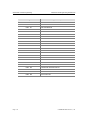
Technician Level Programming
MMC Program No.
Program Description
MMC : 800
ENABLE TECHNICIAN PROGRAM
MMC : 801
CHANGE TECHNICIAN PASSCODE
MMC : 802
CUSTOMER ACCESS MMC NUMBER
MMC : 803
ASSIGN TENANT GROUP
MMC : 804
SYSTEM I/O PARAMETER
MMC : 805
LEVEL AND GAIN
MMC : 806
CARD PRE-INSTALL
MMC : 807
PHONE VOLUME CONTROL
MMC : 809
SYSTEM MMC SANGUAGE
MMC : 810
HALT PROCESSING
MMC : 811
RESET SYSTEM
MMC : 812
SET COUNTRY CODE
MMC : 813
HOTEL OPERATION
MMC : 815
CUSTOMER DATABASE COPY
MMC : 816
CONFERENCE GAIN
MMC : 818
PROGRAM DOWNLOAD
MMC : 819
SMART MEDIA FILE CONTROL
MMC : 820
ASSIGN SYSTEM LINK ID
MMC : 821
ASSIGN NETWORK TRUNK
MMC : 822
SET VIRTUAL EXTENSION TYPE
MMC : 823
ASSIGN NETWORK COS
MMC : 824
NETWORK DIAL TRANSLATION
MMC : 825
ASSIGN NETWORKING OPTION
MMC : 826
ASSIGN SYSTEM REFERENCE CLOCK
© SAMSUNG Electronics Co., Ltd.
Page 1-13
CHAPTER 1. Before Programming
OfficeServ 500 Programming Guide/Ed.00
MMC Program No.
Page 1-14
Program Description
MMC : 829
LAN PRINTER PARAMETER
MMC : 830
ETHERNET PARAMETERS
MMC : 831
MGI PARAMETERS
MMC : 832
VOIP ACCESS CODE
MMC : 833
VoIP IP TABLE
MMC : 834
H.323 OPTIONS
MMC : 835
MGI DSP OPTIONS
MMC : 836
H.323 GK OPTIONS
MMC : 837
SIP OPTIONS
MMC : 840
IP PHONE INFOMATION
MMC : 841
SYSTEM IP OPTIONS
MMC : 850
SYSTEM RESOURCE DISPLAY
MMC : 851
ALARM REPORTING
MMC : 852
SYSTEM ALARM ASSIGNMENTS
MMC : 853
MAINTENANCE BUSY
MMC : 854
DIAGNOSTIC TIME
MMC : 855
SYSTEM OPTIONS
MMC : 856
TECH PROGRAMMING LOGS
MMC : 858
ASSIGN SYSTEM EMERGENCY ALARM
MMC : 859
HARDWARE VERSION DISPLAY
MMC : 860
UCD STATUS SERVICE
MMC : 861
SYSTEM OPTIONS
MMC : 890
INITIALIZE PORT
© SAMSUNG Electronics Co., Ltd.
OfficeServ 500 Programming Guide/Ed.00
5
CHAPTER 1. Before Programming
Overview of Programming Procedure
Here, the order of programming will be discussed before explaining programming
method of each list. Please read the description carefully before programming.
The programming order is as follows :
1) Make the programmable state.
Press the Transfer button at pause.
Enter the program number, either 200 or 800.
Enter either the operator passcode or the technician passcode.
Press 1 dial button to enable the programming mode.
In case of Program 800 Technician Program Mode Setting, enter the tenant
number to be programmed.
2) Make the program number selectable state.
If the Speaker button is pressed, the program selection mode appears.
Or, if the Transfer button is pressed, the programming state ends and the pause
state begin.
3) Select a program.
Enter the program number.
Or, select the program number with the Volume button and press the Speaker
button.
Or, Press Transfer button in a pause state and enter the program number.
4)
Start programming the corresponding program.
© SAMSUNG Electronics Co., Ltd.
Page 1-15
CHAPTER 1. Before Programming
OfficeServ 500 Programming Guide/Ed.00
This page is intentionally left blank
Page 1-16
© SAMSUNG Electronics Co., Ltd.
CHAPTER 2
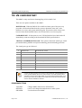
MMC Programming
In this chapter, how to use each program will be discussed according to each program list.
First, you set the phone in the programmable state, then either set or change the value
according to the corresponding programming procedure. To set the phone in the
programmable state, see the Overview of Programming Procedure of chapter1 in this
guide.
© SAMSUNG Electronics Co., Ltd.
Page 2-1
CHAPTER 2. MMC Programming
OfficeServ 500 Programming Guide/Ed.00
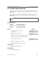
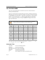
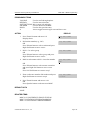
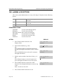
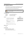
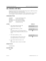
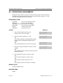
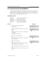
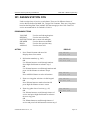
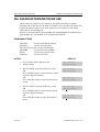
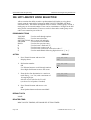
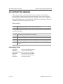
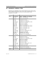
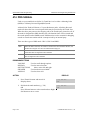
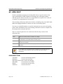
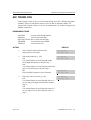
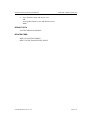
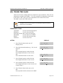
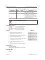
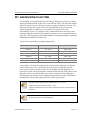
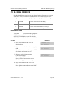
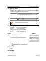
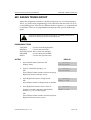
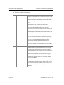
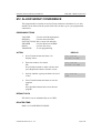
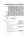
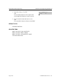
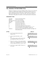
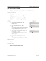
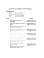
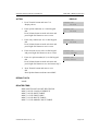
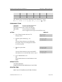
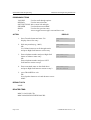
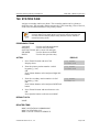
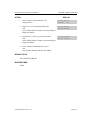
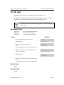
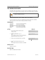
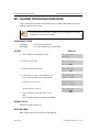
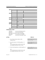
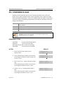
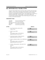
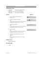
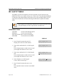
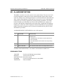
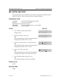
100 STATION LOCK
Allows the system administrator or technician to lock or unlock an individual station
or all stations simultaneously. The three options are as follows :
0
UNLOCKED
Unlocks a locked station.
1
LOCKED OUT
The phone cannot make calls outside the system. It can however make
and receive intercom calls and receive incoming Trunk Line calls. When
in this mode the Hold button of the phone will flash slow RED.
2
LOCKED ALL
The phone cannot make or receive any calls. When in this mode the Hold
button of the phone will light steady RED.
PROGRAM BUTTONS
VOLUME
KEYPAD
SOFT BUTTONS
SPEAKER
HOLD
ANS/RLS
Used to scroll through options
Used to enter selections
Move cursor left and right
Used to advance next MMC
Used to clear previous entry
Used to select ALL
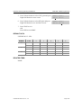
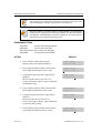
ACTION
DISPLAY
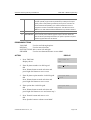
1. Press Transfer button and enter 100
Display shows
[201] STN LOCK
UNLOCKED
2. Dial station number(e.g., 205)
OR
Press Volume button to select station and use
Right Soft button to move cursor
OR
Press ANS/RLS button to select all stations
[205] STN LOCK
UNLOCKED
3. Enter 0 to unlock or 1 to lock(e.g., 1)
OR
Press Volume button to make selection and press
Right Soft button to return to step 2
[205] STN LOCK
LOCKED OUT
[ALL] STN LOCK
?
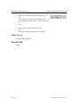
4. Press Transfer button and enter to save and exit
OR
Press Speaker button to save and advance to next
MMC
DEFAULT DATA
ALL STATIONS UNLOCKED
RELATED ITEMS
STATION USER PROGRAMMING
Page 2-2
© SAMSUNG Electronics Co., Ltd.
OfficeServ 500 Programming Guide/Ed.00
CHAPTER 2. MMC Programming
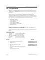
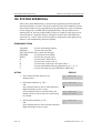
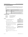
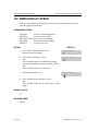
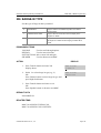
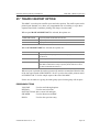
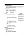
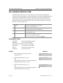
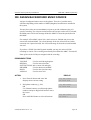
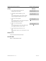
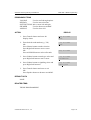
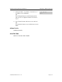
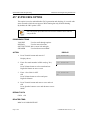
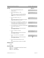
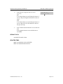
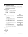
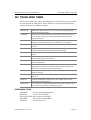
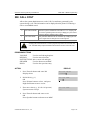
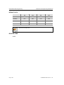
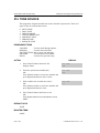
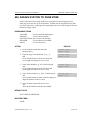
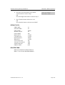
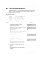
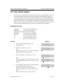
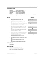
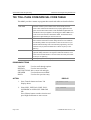
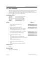
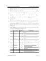
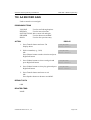
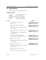
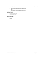
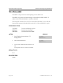
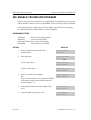
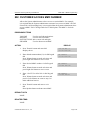
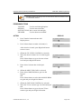
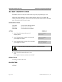
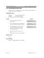
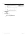
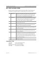
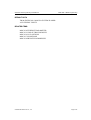
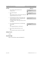
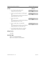
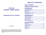
101 CHANGE USER PASSCODE
Allows the system administrator or technician to reset any phones passcode to its
default value of 1234. This MMC cannot display station passcodes; it can only reset
them to default.
Phone users can set or change their individual passcodes. The passcode is used to
lock or unlock the phone for toll restriction(call barring) override and to access the
DISA feature.
Default passcodes cannot be used for toll restriction override or for DISA access.
PROGRAM BUTTONS
VOLUME
KEYPAD
SOFT BUTTONS
SPEAKER
HOLD
Used to scroll through options
Used to enter selections
Move cursor left and right
Used to advance next MMC
Used to clear previous entry
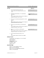
ACTION
DISPLAY
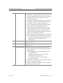
1. Press Transfer button and enter 101
Display shows
[201] PASSCODE
PASSCODE:****
2. Dial phone number(e.g., 205)
OR
Use Volume button to scroll through phone numbers
and
press Right Soft button to move the cursor right
[205] PASSCODE
PASSCODE:****
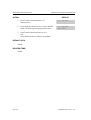
3. Press HOLD to reset passcode
[205] PASSCODE
PASSCODE:1234
4. Press Transfer button and enter to exit
OR
Press Speaker button to advance next MMC
DEFAULT DATA
ALL STATION PASSCODES=1234
RELATED ITEMS
MMC 100 STATION LOCK
© SAMSUNG Electronics Co., Ltd.
Page 2-3
CHAPTER 2. MMC Programming
OfficeServ 500 Programming Guide/Ed.00
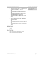
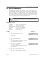
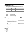
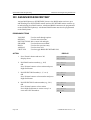
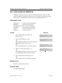
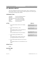
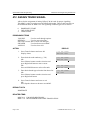
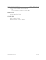
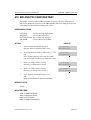
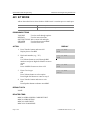
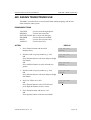
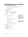
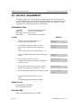
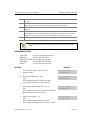
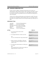
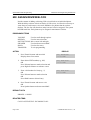
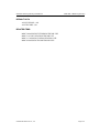
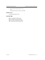
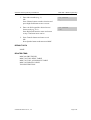
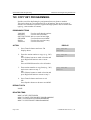
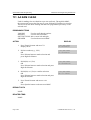
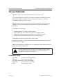
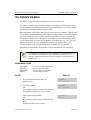
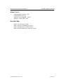
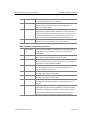
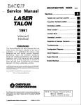
102 CALL FORWARD
Allows the system administrator to program the call forward destinations for other
station users. This MMC also allows call forward to be set after the destination has
been entered.
Allows several types of call forwarding : FORWARD ALL, FORWARD NO
ANSWER, FORWARD BUSY and FORARD DND. There is an additional option,
FORWARD BUSY/NO ANSWER, that allows both of these options to be activated
at the same time, provided that destinations have been entered for both.
0
1
2
3
4
5
FORWARD CANCEL
FORWARD ALL CALL
FORWARD BUSY
FORWARD NO ANSWER
FORWARD BUSY/NO ANSWER
FORWARD DND
All types forwarding can be set external number.
In MMC 701 Class of Service, if FORWARD is set OFF, you cannot set call
forward but can cancel it. And if EXT FWD is set OFF, you cannot set external
number.
PROGRAM BUTTONS
VOLUME
KEYPAD
SOFT BUTTONS
SPEAKER
HOLD
Used to scroll through options
Used to enter selections
Move cursor left and right
Used to advance next MMC
Used to clear previous entry
ACTION
Page 2-4
DISPLAY
1. Press Transfer button and enter 102
Display shows
[201] FORWARD
2. Dial station number(e.g., 205)
OR
Press Volume button to select station and press
RIGHT
Soft button to move cursor
[205] FORWARD
0:FORWARD CANCEL
0:FORWARD CANCEL
© SAMSUNG Electronics Co., Ltd.
OfficeServ 500 Programming Guide/Ed.00
CHAPTER 2. MMC Programming
3. Dial 0-* to select forward type
OR
Press Volume button to select forward type and
press Right Soft button to move cursor
[205] FORWARD
4. Dial destination number(e.g., 201)
OR
Press Volume button to select destination and
press Right Soft button to move cursor
[205] FORWARD
5. Dial 1 for YES, 0 for NO
OR
Press Volume button to select YES or NO and
press Right Soft button to return to step 2
[205] FORWARD
1:ALL CALL:NONE
1:ALL CALL:201
CURENTLY SET :YES
6. Press Transfer button and enter to exit
OR
Press Speaker button to advance to next MMC
DEFAULT DATA
NONE
RELATED ITEMS
MMC 301 ASSIGN STATION COS
MMC 501 SYSTEM TIMERS
MMC 502 STATION TIMERS
MMC 701 ASSIGN COS CONTENTS
MMC 722 STATION KEY PROGRAMMING
MMC 723 SYSTEM KEY PROGRAMMING
© SAMSUNG Electronics Co., Ltd.
Page 2-5
CHAPTER 2. MMC Programming
OfficeServ 500 Programming Guide/Ed.00
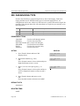
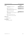
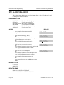
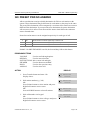
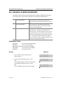
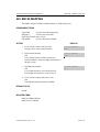
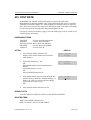
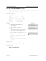
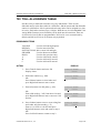
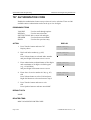
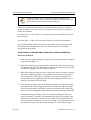
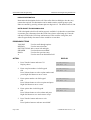
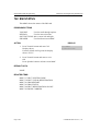
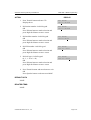
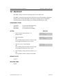
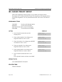
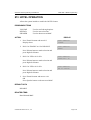
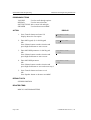
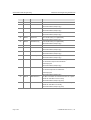
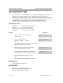
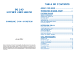
103 SET ANSWER MODE
Allows the system administrator to change the answer mode of any phone.
Each phone can have its answer mode set to one of the following options :
0
RING MODE
The phone will ring in one of eight custom ring patterns.
Calls are answered by pressing the ANS/RLS Button or by
lifting the handset.
1
AUTO ANSWER MODE
After giving a short attention tone, the phone will
automatically answer calls on the speakerphone. When a
Trunk line is transferred to a phone in Auto Answer, the
screened portion of the call will be Auto Answer, but the
phone will ring when the transfer is complete if you have not
pressed the ANS/RLS Button or lifted the handset.
2
VOICE ANNOUNCE
The phone will not ring. After a short attention tone, callers
can make an announcement but the ANS/RLS Button or
handset must be used to answer calls.
PROGRAM BUTTONS
VOLUME
KEYPAD
SOFT BUTTONS
SPEAKER
HOLD
ANS/RLS
Used to scroll through options
Used to enter selections
Move cursor left and right
Used to advance next MMC
Used to clear previous entry
Used to select ALL
ACTION
Page 2-6
DISPLAY
1. Press Transfer button and enter 103
Display shows
[201] ANS MODE
2. Dial phone number(e.g., 205)
OR
Press Volume button to select phone and press
Right Soft button to move cursor
OR
Press ANS/RLS button to select All
[205] ANS MODE
3. Dial 0, 1 or 2 to change ring mode
OR
Press Volume button to select ring mode and
press Right Soft button to return to step 2 above
[205] ANS MODE
RING MODE
RING MODE
[ALL] ANS MODE
?
VOICE ANNOUNCE
© SAMSUNG Electronics Co., Ltd.
OfficeServ 500 Programming Guide/Ed.00
CHAPTER 2. MMC Programming
4. Press Transfer button and enter to exit
OR
Press Speaker button to advance next MMC
DEFAULT DATA
ALL PHONES RING
RELATED ITEMS
MMC 111 PHONE RING TONE
© SAMSUNG Electronics Co., Ltd.
Page 2-7
CHAPTER 2. MMC Programming
OfficeServ 500 Programming Guide/Ed.00
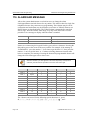
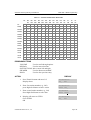
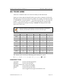
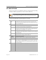
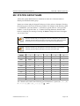
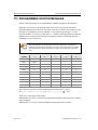
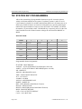
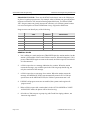
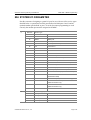
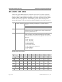
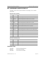
104 STATION NAME
Allows the system administrator or technician to enter an 11-character name to
identify an individual station.
Names are written using the keypad. Each key press selects a character. Pressing the
dial pad key moves the cursor to the next position. For example, if the directory name
is SAM SMITH, press the number 7 four times to get the letter S. Now press the
number 2 once to get the letter A. Continue selecting characters from the table
below to complete your message. Pressing A button will change the letter from
upper case to lower case.
When the character you want appears on the same dial pad key as the previous
character, press the Volume Up button to move the cursor to the right.
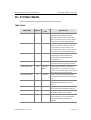
COUNT
1
2
3
4
5
DIAL 0
<
>
.
)
0
DIAL 1
Space
?
,
!
1
DIAL 2
A
B
C
@
2
DIAL 3
D
E
F
#
3
DIAL 4
G
H
I
$
4
DIAL 5
J
K
L
%
5
DIAL 6
M
N
O
^
6
DIAL 7
P
Q
R
S
7
DIAL 8
T
U
V
*
8
DIAL 9
W
X
Y
Z
9
DIAL *
:
=
[
]
*
The # button can be used for the following special characters : #, space, &, !, : , ?, ., ,, %, $, -,
<, >, /, =, [, ], @, ^, (, ), _, +, {, }, |, ; , ", ,` , and \.
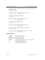
PROGRAM BUTTONS
VOLUME
KEYPAD
SOFT BUTTONS
SPEAKER
HOLD
A
Page 2-8
Used to scroll through options
Used to enter selections
Move cursor left and right
Used to advance next MMC
Used to clear previous entry
Acts as toggle between upper case and lower case
© SAMSUNG Electronics Co., Ltd.
OfficeServ 500 Programming Guide/Ed.00
CHAPTER 2. MMC Programming
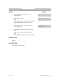
ACTION
DISPLAY
1. Press Transfer button and enter 104
Display shows
[201] STN NAME
2. Dial station number(e.g., 205)
OR
Press Volume button to select station and press
Right Soft button to move cursor
[205] STN NAME
3. Enter the station name using the procedure
described above and press Right Soft button to
return to step 2
[205] STN NAME
_
SAM SMITH
4. Press Transfer button and enter to exit
OR
Press Speaker button to advance next MMC
DEFAULT DATA
NONE
RELATED ITEMS
NONE
© SAMSUNG Electronics Co., Ltd.
Page 2-9
CHAPTER 2. MMC Programming
OfficeServ 500 Programming Guide/Ed.00
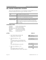
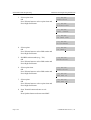
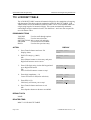
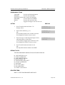
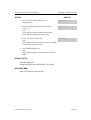
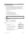
105 STATION SPEED DIAL
Allows the system administrator or technician to program the personal speed dial
locations assigned to a station. This must be done for single line telephones because
these stations cannot access programming. Each station may have up to 50 locations
or bins assigned to it in MMC 606 Assign Speed Block. The speed dial bins are
numbered 00~49. Each speed dial number consists of a trunk or trunk group access
code followed by a separator and up to 24 digits to be dial. These dial digits may
consist of 0~9, * and #. If the system recognizes a valid trunk or trunk group access
number, it will automatically insert the separator.
PROGRAM BUTTONS
VOLUME
KEYPAD
SOFT BUTTONS
SPEAKER
HOLD
B
C
D
E
F
Used to scroll through options
Used to enter selections
Move cursor left and right
Used to advance next MMC
Used to clear previous entry
Used to insert a flash code F
Used to insert a pause code P
Used to insert a pulse/tone conversion code C
Used to mask/unmask following digits(shows as [ or ])
Used to enter name for speed dial bin(see MMC 106)
ACTION
DISPLAY
1. Press Transfer button and enter 105
Display shows
[201] SPEED DIAL
2. Dial station number(e.g., 205)
OR
Press Volume button to select station and press
Right Soft button to move cursor
If selected station has no speed dial bins, the
display will be as shown and a new station may
be selected.
[205] SPEED DIAL
3. Dial location number(e.g., 05)
OR
Press Volume button to select location and press
Right Soft button to move cursor
[205] SPEED DIAL
Page 2-10
00:
00:
[205] SPEED DIAL
SPDBLK NOT EXIST
05:_
© SAMSUNG Electronics Co., Ltd.
OfficeServ 500 Programming Guide/Ed.00
4. Enter trunk access code(e.g., 9) followed by the
number to be dialled(e.g., 4264100)
OR
Press the Right Soft button to return to step 2
OR
Press the Left Soft button to return to step 3
Press HOLD button to clear an entry
If an error is made, use DOWN arrow to step
back
CHAPTER 2. MMC Programming
[205] SPEED DIAL
05:9-4264100_
5. Press F button to access MMC 106 Station
Speed Dial Name
OR
Press Transfer button and enter to save and exit
OR
Press Speaker button to save and advance to next
MMC
DEFAULT DATA
NONE
RELATED ITEMS
MMC 106 STATION SPEED DIAL NAME
MMC 606 ASSIGN SPEED BLOCK
© SAMSUNG Electronics Co., Ltd.
Page 2-11
CHAPTER 2. MMC Programming
OfficeServ 500 Programming Guide/Ed.00
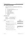
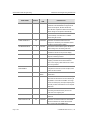
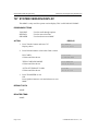
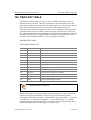
106 STATION SPEED DIAL NAME
Allows an 11-character name to be entered for each personal speed dial location. This
name enables the speed dial number to be located when the directory dial feature is
used. The directory dial feature allows the display phone user to select a speed dial
location by viewing its name.
Names are written using the keypad. Each key press selects a character. Pressing the
dial pad key moves the cursor to the next position. For example, if the directory name
is SAM SMITH, press the number 7 four times to get the letter S. Now press the
number 2 once to get the letter A. Continue selecting characters from the table
below to complete your message. Pressing A button will change the letter from
upper case to lower case.
When the character you want appears on the same dial pad key as the previous
character, press the Volume Up button to move the cursor to the right.
COUNT
1
2
3
4
5
DIAL 0
<
>
.
)
0
DIAL 1
Space
?
,
!
1
DIAL 2
A
B
C
@
2
DIAL 3
D
E
F
#
3
DIAL 4
G
H
I
$
4
DIAL 5
J
K
L
%
5
DIAL 6
M
N
O
^
6
DIAL 7
P
Q
R
S
7
DIAL 8
T
U
V
*
8
DIAL 9
W
X
Y
Z
9
DIAL *
:
=
[
]
*
The # button can be used for the following special characters : #, space,
&, !, :, ?, ., ,, %, $, -, <, >, /, =, [, ], @, ^, (, ), _, +, {, }, |, ; , ", ,` , and \.
Page 2-12
© SAMSUNG Electronics Co., Ltd.
OfficeServ 500 Programming Guide/Ed.00
CHAPTER 2. MMC Programming
PROGRAM BUTTONS
VOLUME
KEYPAD
SOFT BUTTONS
SPEAKER
HOLD
A
Used to scroll through options
Used to enter selections
Move cursor left and right
Used to advance next MMC
Used to clear previous entry
Acts as toggle between upper case and lower case
ACTION
DISPLAY
1. Press Transfer button and enter 106
Display shows
[201] SPEED NAME
2. Dial station number(e.g., 205)
OR
Press Volume button to select station and press
Right Soft button to move cursor
If selected station has no speed dial bins, the
display will be as shown and a new station may
be selected
[205] SPEED NAME
3. Dial speed dial location(e.g., 01)
OR
Press Volume button to scroll through location
numbers and press Right Soft button to move
cursor
[205] SPEED NAME
4. Enter the location name using the procedure
described above and press Right Soft button to
return to step 2
[205] SPEED NAME
00:
00:
[305] SPEED NAME
SPDBLK NOT EXIST
01:_
01:SAM SMITH
5. Press Transfer button and enter to exit
OR
Press Speaker button to advance next MMC
DEFAULT DATA
NONE
RELATED ITEMS
MMC 105 STATION SPEED DIAL
MMC 606 ASSIGN SPEED BLOCK
© SAMSUNG Electronics Co., Ltd.
Page 2-13
CHAPTER 2. MMC Programming
OfficeServ 500 Programming Guide/Ed.00
107 KEY EXTENDER
Use this program to view the programmable buttons assigned to phone station.
In addition, it allows the system administrator to assign key extenders to some keys
that will make a general access feature key more specific. The feature keys that can
have extenders are listed below.
FEATURE
EXTENDER
AB
Absence(extension number)
ACC
Account code bin(000-999)
BOOK
Booking function number(Stations Speed Dial Number : 00-49)
BOSS
Boss and Secretary(1-4)
CR
VM Call Record
CS
UCD Call Status(UCD group number)
DIR
Directory dial by name type(1-3)
DP
Direct Pickup(extension or station group number)
DS
Direct Station Select(station number)
FWRD
Call Forward(0-7)
GPIK
Group Pickup(01-99)
IG
IN/Out of Group(station group number)
MMPG
Meet Me Page(0-9, * )
MW
Message Waiting(extension or station group number)
PAGE
Page(0-9, * )
PARK
Park Orbits(0-9)
RP
Ring Plan(1-6)
RSV
Room Status View(1-5)-Available in Hotel/Motel enabled only
SG
Station Group(station group number)
PMSG
Programmed Station Messaging(01-20)
SP
UCD Supervisor(UCD group number)
SPD
Speed Dial(00-49, 500-999)
VG
SVM-800 Group Message(station group number)
VM
VM Memo(extension or station group number)
VT
Voice Transfer(VM group number)
When the Right Soft button will not move the cursor to the right, you are attempting to
add an extender to a key that cannot have one.
Page 2-14
© SAMSUNG Electronics Co., Ltd.
OfficeServ 500 Programming Guide/Ed.00
CHAPTER 2. MMC Programming
PROGRAM BUTTONS
VOLUME
KEYPAD
SOFT BUTTONS
SPEAKER
HOLD
Used to scroll through options
Used to enter selections
Move cursor left and right
Used to advance next MMC
Used to clear previous entry
ACTION
DISPLAY
1. Press Transfer button and enter 107
Display shows first station
[201] EXT (MAST)
01:CALL1
2. Dial station number(e.g., 205)
OR
Use Volume button to scroll through station
numbers and press Right Soft button to move the
cursor
[205] EXT (MAST)
01:CALL1
3. Press the Right Soft button to
program the phone
OR
Use Volume button to scroll through the phone and
AOMs and use the Right Soft button to move the
cursor
[201] EXT (MAST)
01:CALL1
4. Enter key number(e.g., 18)
OR
Use Volume button to scroll through keys and use
Right Soft button to move the cursor
OR
Press the key to be programmed
Dial extender according to above table.
System will return to this step. If no more entries,
press Left Soft button to return to step 2
[205] EXT (MAST)
18:DS
[201] EXT (AOM1)
01:DS
[205] EXT (MAST)
18:DS207
5. Press Transfer button and enter to exit
OR
Press Speaker button to advance next MMC
DEFAULT DATA
NONE
RELATED ITEMS
MMC 720 COPY KEY PROGRAMMING
MMC 721 SAVE STATION KEY PROGRAMMING
MMC 722 STATION KEY PROGRAMMING
MMC 723 SYSTEM KEY PROGRAMMING
MMC 724 DIAL NUMBERING PLAN
© SAMSUNG Electronics Co., Ltd.
Page 2-15
CHAPTER 2. MMC Programming
OfficeServ 500 Programming Guide/Ed.00
108 STATION STATUS
Displays the following attributes of a station port. This is a READ-ONLY MMC :
0
PORT #
Cabinet(1~3)/Slot(1~9)/Port(1~16)
1
TYPE
Phone Type
2
PICKUP GROUP
None, 01~99
3
SGR
Station Group Number
4
BOSS-SECR
None, 1-4
5
PAGE
None, Page Zone(0~4, * )
6
COS NO
COS(1-30) per Ring Plan(01-06)
9
TENANT GROUP
Tenant Group Number(1~2)
PROGRAM BUTTONS
VOLUME
KEYPAD
SOFT BUTTONS
SPEAKER
Used to scroll through options
Used to enter selections
Move cursor left and right
Used to advance next MMC
ACTION
1.
2.
DISPLAY
Press Transfer button and enter 108
Display shows first station
[201] STN STATUS
Dial station number(e.g., 205)
[205] STN STATUS
Press Volume button to select station and press
Right Soft button to move cursor
3.
4.
Page 2-16
Dial 0~9 to select station status type
OR
Press Volume button to select status and press
Right Soft button to return to step 2
PORT:C1-S3-P01
PORT:C1-S3-P05
[205] STN STATUS
PICKUP GROUP:01
Press Transfer button and enter to exit
OR
Press Speaker button to advance next MMC
© SAMSUNG Electronics Co., Ltd.
OfficeServ 500 Programming Guide/Ed.00
CHAPTER 2. MMC Programming
DEFAULT DATA
PORT # : FOLLOWS HARDWARE POSITION
TYPE : DEPENDENT ON CONNECTED PHONE
PICKUP GRP : NONE
SGR : NONE
BOSS-SECR : NONE
PAGE ZONE : NONE
COS NUMBER : 01 IN ALL RING PLANS
TENANT GRP : 1
RELATED ITEMS
MMC 301 ASSIGN STATION COS
MMC 302 PICKUP GROUPS
MMC 303 ASSIGN BOSS/SECRETARY
MMC 601 ASSIGN STATION GROUP
MMC 604 ASSIGN STATION TO PAGE ZONE
© SAMSUNG Electronics Co., Ltd.
Page 2-17
CHAPTER 2. MMC Programming
OfficeServ 500 Programming Guide/Ed.00
109 DATE DISPLAY
Allows the system administrator or technician to select the date and time display
mode on a per-station basis or system-wide.
0
1
2
COUNTRY
CLOCK
DISPLAY
Sets overall display format and has two options :
0=ORIENTAL
MM/DD DAY
HH:MM
1=WESTERN
DAY DD MON
HH:MM
Sets format of clock display and has two options :
0=12 HOUR
Displays 1 P.M. as 01:00
1=24 HOUR
Displays 1 P.M. as 13:00
Sets format of DAY and MON display and has two options :
0=UPPER CASE
Displays Friday as FRI and March as MAR
1=LOWER CASE
Displays Friday as Fri and March as Mar
PROGRAM BUTTONS
VOLUME
KEYPAD
SOFT BUTTONS
SPEAKER
HOLD
ANS/RLS
Used to scroll through options
Used to enter selections
Move cursor left and right
Used to advance next MMC
Used to clear previous entry
Used to select ALL
ACTION
DISPLAY
1. Press Transfer button and enter 109
Display shows
[201] DAY FORMAT
2. Dial station number(e.g., 205)
[205] DAY FORMAT
Press Volume button to select station and press
Right Soft button to move cursor
OR
Press ANS/RLS button for all phones
3. Dial 0~2 to select mode
OR
Press Volume button to scroll through modes and
press Right Soft button to move cursor
COUNTRY:WESTERN
COUNTRY:WESTERN
[ALL] DAY FORMAT
COUNTRY:?
[205] DAY FORMAT
COUNTRY:ORIENTAL
4. Press Volume button to scroll through formats
and press Right Soft button to return to step 2
Page 2-18
© SAMSUNG Electronics Co., Ltd.
OfficeServ 500 Programming Guide/Ed.00
CHAPTER 2. MMC Programming
5. Press Transfer button and enter to exit
OR
Press Speaker button to advance next MMC
DEFAULT DATA
COUNTRY : WESTERN
CLOCK : 12 HOUR
DISPLAY : LOWER CASE
RELATED ITEMS
MMC 505 ASSIGN DATE AND TIME
© SAMSUNG Electronics Co., Ltd.
Page 2-19
CHAPTER 2. MMC Programming
OfficeServ 500 Programming Guide/Ed.00
110 STATION ON/OFF
Allows the system administrator to set any of the phone features listed below.
FEATURES
00
AUTO HOLD
DEFAULT
OFF
DESCRIPTION
Automatically places an existing Trunk Line call on hold if a
CALL button, trunk key or trunk route key is pressed during
that call.
01
AUTO TIMER
ON
Automatically starts the stopwatch timer during a Trunk
Line call.
02
HEADSET USE
OFF
When ON, this feature disables the hook switch allowing a
headset user to answer all calls by pressing the ANS/RLS
button.
03
HOT KEYPAD
ON
When ON, this feature allows you to dial directory numbers
without having to first lift the handset or press the Speaker
button.
04
KEY TONE
ON
Allows you to hear a slight tone when pressing buttons on
05
PAGE REJOIN
ON
Allows you to hear the latter part of page announcements if
06
RING PREF.
ON
phone.
phone becomes free during a page.
When OFF, requires you to press the fast flashing button to
answer a ringing call after lifting the handset.
07
CALL COST
OFF
When ON, the cost of the call in progress will show in the
upper right corner of the phone display instead of duration
of the call.
08
AUTO CAMPON
OFF
09
AME BGM
OFF
When ON, phone users can allow intercom calls to camp-on
to other phones without having to press a CAMP-ON key.
This feature selects whether a station using Answer
Machine Emulation will hear their personal greeting or
BGM while callers are listening to the personal greeting.
A BGM source must be selected for this to work.
10
AME PASSCODE
OFF
When ON, station users who have AME set must enter
their station password to listen to messages being left.
11
DISP SPDNAME
OFF
When ON, the speed dial name associated with a speed
dial number is displayed on a phone equipped a LCD
display when using speed dial.
12
CID REVW ALL
ON
When ON, saves information on all calls that ring at an
extension, When OFF, saves information only on calls that
were not answered at the extension or by voice mail.
13
SECURE OHVA
ON
When ON, OHVA announcements will be heard on the
handset. When OFF, OHVA announcements will be heard
over the phone speaker.
Page 2-20
© SAMSUNG Electronics Co., Ltd.
OfficeServ 500 Programming Guide/Ed.00
FEATURES
CHAPTER 2. MMC Programming
DEFAULT
14
NOT CONT.CID
ON
15
AUTO ANS CO
OFF
DESCRIPTION
When OFF, the Caller ID will be continue display after the
phone user answered call.
When On, the incoming CO call will be answered follows
phone answer mode.
PROGRAM BUTTONS
VOLUME
KEYPAD
SOFT BUTTONS
SPEAKER
HOLD
ANS/RLS
Used to scroll through options
Used to enter selections
Move cursor left and right
Used to advance next MMC
Used to clear previous entry
Used to select ALL
ACTION
DISPLAY
1. Press Transfer button and enter 110
Display shows
[201] STN ON/OFF
2. Dial the option number from above list(e.g., 4)
OR
Press Volume button to select the option and press
the Right Soft button to move the cursor
[201] STN ON/OFF
3. Press Volume button to select ON or OFF
Press the Left or Right Soft button to return to step 2
OR
Dial 1 for ON or 0 for OFF
[201] STN ON/OFF
AUTO HOLD
HOT KEYPAD
HOT KEYPAD
:OFF
:OFF
:ON
4. Press Transfer button and enter to exit
DEFAULT DATA
SEE DESCRIPTION
SOME OPTIONS ARE DEPEND ON COUNTRY
RELATED ITEMS
MMC 301 ASSIGN STATION COS
MMC 701 ASSIGN COS CONTENTS
© SAMSUNG Electronics Co., Ltd.
Page 2-21
CHAPTER 2. MMC Programming
OfficeServ 500 Programming Guide/Ed.00
111 PHONE RING TONE
Allows the system administrator or technician to select the ring tone heard at each
phone. There are eight ring tones available at each phone. A short tone burst of the
selection will be heard when the dial keypad is pressed.
PROGRAM BUTTONS
VOLUME
KEYPAD
SOFT BUTTONS
SPEAKER
HOLD
ANS/RLS
Used to scroll through options
Used to enter selections
Move cursor left and right
Used to advance next MMC
Used to clear previous entry
Used to select ALL
ACTION
DISPLAY
1. Press Transfer button and enter 111
Display shows
[201] RING TONE
2. Dial phone number(e.g., 205)
OR
Press Volume button to select station and press
Right Soft button to move cursor
OR
Press ANS/RLS button to select All
[205] RING TONE
3. Dial 1~8 to select ring tone
OR
Press Volume button to select ring tone and press
Right Soft button to move cursor
[205] RING TONE
SELECTION
SELECTION
5
5
[ALL] RING TONE
SELECTION
SELECTION
?
5
4. Press Transfer button and enter to exit
OR
Press Speaker button to advance next MMC
DEFAULT DATA
FREQUENCY 5
RELATED ITEMS
MMC 114 PHONE VOLUME
Page 2-22
© SAMSUNG Electronics Co., Ltd.
OfficeServ 500 Programming Guide/Ed.00
CHAPTER 2. MMC Programming
112 ALARM REMINDER CLOCK
Allows the system administrator or technician to set or change the alarm
clock/appointment reminder feature for any station. This must be done for single line
telephones, as they cannot access programming. Three alarms may be set for each
station and each alarm may be defined as a one-time or TODAY alarm or as a DAILY
alarm, as described below. The TODAY alarm is automatically cancelled after it rings,
while the DAILY alarm rings every day at the same time. Alarm numbers are 1, 2 and
3. In the case of Secondary Pair assignments(MMC 220) the alarm only rings the
station that is programmed and does not ring the paired station.
0
NOTSET
No alarm
1
TODAY
Alarm only once
2
DAILY
Alarm daily at set time
PROGRAM BUTTONS
VOLUME
KEYPAD
SOFT BUTTONS
SPEAKER
HOLD
Used to scroll through options
Used to enter selections
Move cursor left and right
Used to advance next MMC
Used to clear previous entry
ACTION
DISPLAY
1. Press Transfer button and enter 112
Display shows
[201] ALM CLK(1)
2. Dial station number(e.g., 205)
[205] ALM CLK(1)
Press Volume button to select station and press
Right Soft button
HHMM: NOTSET
HHMM: NOTSET
3. Dial 1~3 to select alarm(e.g., 1)
OR
Press Volume button to select alarm and press
Right Soft button
[205] ALM CLK(1)
4. Enter alarm time in 24-hour clock format
(e.g., 1300 for 1pm)
[205] ALM CLK(2)
© SAMSUNG Electronics Co., Ltd.
HHMM: NOTSET
HHMM:1300 NOTSET
Page 2-23
CHAPTER 2. MMC Programming
OfficeServ 500 Programming Guide/Ed.00
5. Dial entry from above list for alarm type(e.g., 2)
OR
Press Volume button to select alarm type and
press Right Soft button to move cursor and return
to
step 2
[205] ALM CLK(2)
HHMM:1300 DAILY
6. Press Transfer button and enter to exit
OR
Press Speaker button to advance next MMC
DEFAULT DATA
ALARMS ARE NOTSET
RELATED ITEMS
NONE
Page 2-24
© SAMSUNG Electronics Co., Ltd.
OfficeServ 500 Programming Guide/Ed.00
CHAPTER 2. MMC Programming
113 VIEW MEMO NUMBER
Allows a station user the ability to view a memo left by the user. A memo can be left
by entering it via the dial keypad using the table below. A memo of up to and
including 13 characters can be entered. For example, using the dial keypad, press 6
once to enter the letter M, and press 3 twice for an E. Pressing the A button will
change the letters from upper case to lower case.
When the character you want appears on the same dial pad key as the previous
character, press the Volume Up button to move the cursor to the right.
COUNT
1
2
3
4
5
DIAL 0
<
>
.
)
0
DIAL 1
Space
?
,
!
1
DIAL 2
A
B
C
@
2
DIAL 3
D
E
F
#
3
DIAL 4
G
H
I
$
4
DIAL 5
J
K
L
%
5
DIAL 6
M
N
O
^
6
DIAL 7
P
Q
R
S
7
DIAL 8
T
U
V
*
8
DIAL 9
W
X
Y
Z
9
DIAL *
:
=
[
]
*
The # button can be used for the following special characters: #, space,
&, !, :, ?, ., ,, %, $, -, <, >, /, =, [, ], @, ^, (, ), _, +, {, }, |, ;,", ,` , and \.
PROGRAM BUTTONS
VOLUME
KEYPAD
SOFT BUTTONS
SPEAKER
HOLD
A
© SAMSUNG Electronics Co., Ltd.
Used to scroll through options
Used to enter selections
Move cursor left and right
Used to advance next MMC
Used to clear previous entry
Acts as toggle between upper case and lower case
Page 2-25
CHAPTER 2. MMC Programming
OfficeServ 500 Programming Guide/Ed.00
ACTION
DISPLAY
1. Press Transfer button and enter 113
Display shows
[201] VIEW MEMO
2. Press Right Soft button to move cursor and add
memo via dial keypad using procedure above
[205] VIEW MEMO
1:
1:NEED BREAD
3. Press Transfer button and enter to exit
OR
Press Speaker button to advance next MMC
DEFAULT DATA
NONE
RELATED ITEMS
NONE
Page 2-26
© SAMSUNG Electronics Co., Ltd.
OfficeServ 500 Programming Guide/Ed.00
CHAPTER 2. MMC Programming
114 PHONE VOLUME
Allows the station user or system administrator to set the ring volume, off hook ring
volume, handset receive volume, speaker volume, background music volume and
page volume for any or all phones.
0
RING VOLUME
This is the volume setting for the phone ringer. There are eight
volume levels : level 1 is the lowest and level 8 the highest.
1
OFF-RING VOL
This is the volume of the alert tone that tells you there is a call
camped on to your phone. There are eight volume levels : level 1 is
the lowest and level 8 the highest.
2
HANDSET VOL
This is the volume setting for conversations on the handset receiver.
There are eight volume levels : level 1 is the lowest and level 8 the
highest.
3
SPEAKER VOL
This is the receive volume setting for conversations on the speaker
phone of a phone. There are 16 volume levels : level 1 is the lowest
and level 16 the highest.
4
BGM VOLUME
This is the volume you will hear background music over the phone
speaker at when your phone is idle and BGM is turned on. There are
16 volume levels : level 1 is the lowest and level 16 the highest.
5
PAGE VOLUME
This is the volume you will hear internal page over the phone
speaker when your phone is idle and BGM is turned on. There are
16 volume levels : level 1 is the lowest and level 16 the highest.
PROGRAM BUTTONS
VOLUME
KEYPAD
SOFT BUTTONS
SPEAKER
ANS/RLS
Used to scroll through options
Used to enter selections
Move cursor left and right
Used to advance next MMC
Used to select ALL
ACTION
DISPLAY
1. Press Transfer button and enter 114
Display shows
[201] STN VOLUME
2. Dial phone number(e.g., 205)
[205] STN VOLUME
RING VOLUME :4
RING VOLUME :4
3. Press Volume button to select volume type
[205] STN VOLUME
SPEAKER VOL :13
© SAMSUNG Electronics Co., Ltd.
Page 2-27
CHAPTER 2. MMC Programming
4. Press Volume button to select volume
OfficeServ 500 Programming Guide/Ed.00
[205] STN VOLUME
SPEAKER VOL :08
5. Press Transfer button and enter to exit
OR
Press Speaker button to advance next MMC
DEFAULT DATA
RING VOLUME : 4
OFF-HOOK RING VOLUME : 4
HANDSET VOLUME : 4
SPEAKER VOLUME : 13
BGM VOLUME : 13
PAGE VOLUME : 13
RELATED ITEMS
MMC 111 PHONE RING TONE
Page 2-28
© SAMSUNG Electronics Co., Ltd.
OfficeServ 500 Programming Guide/Ed.00
CHAPTER 2. MMC Programming
115 SET PROGRAMMED MESSAGE
Allows the system administrator to set a programmed message at any or all phones.
There are 20 messages available. The first ten are pre-programmed and the remaining
entries can be customized in MMC 715, Programmed Station Message. The last five
message are can be modified by each phone user.
PROGRAM BUTTONS
VOLUME
KEYPAD
SOFT BUTTONS
SPEAKER
HOLD
ANS/RLS
Used to scroll through options
Used to enter selections
Move cursor left and right
Used to advance next MMC
Used to clear previous entry
Used to select ALL
ACTION
DISPLAY
1. Press Transfer button and enter 115
Display shows
[201] PGMMSG(00)
2. Dial station number(e.g., 205)
OR
Press Volume button to select station and
press Right Soft button to move cursor
OR
Press ANS/RLS button to select All
[205] PGMMSG(00)
3. Dial an entry number to select message number
(e.g., 05)
OR
Press Volume button to select message and press
Right Soft button to return to step 2
[205] PGMMSG(05)
CANCEL PGM MSG
CANCEL PGM MSG
[ALL] PGMMSG(??)
PAGE ME
4. Press Transfer button and enter to exit
OR
Press Speaker button to advance next MMC
DEFAULT DATA
NO MESSAGES SELECTED
RELATED ITEMS
MMC 715 PROGRAMMED MESSAGE
MMC 722 STATION KEY PROGRAMMING
MMC 723 SYSTEM KEY PROGRAMMING
© SAMSUNG Electronics Co., Ltd.
Page 2-29
CHAPTER 2. MMC Programming
OfficeServ 500 Programming Guide/Ed.00
116 ALARM AND MESSAGE
Allows the system administrator or technician to set or change the alarm
clock/appointment reminder feature for any station. This must be done for single line
telephones because they cannot access programming. Three alarms may be set for
each station and each alarm may be defined as a one-time or TODAY alarm or as a
DAILY alarm, as described below. The TODAY alarm is automatically cancelled
after it rings, while the DAILY alarm rings every day at the same time. It is also
possible to set a message to display when the alarm is sounded.
0
NOTSET
No alarm
1
TODAY
Alarm only once
2
DAILY
Alarm daily at set time
Names are written using the keypad. Each key press selects a character. Pressing the
dial pad key moves the cursor to the next position. For example, if the message is
SAM SMITH, press the number 7 four times to get the letter S. Now press the
number 2 once to get the letter A. Continue selecting characters from the table
below to complete your message. Pressing the bottom left programmable button will
change the letter from upper case to lower case.
When the character you want appears on the same dial pad key as the previous
character, press the Volume Up button to move the cursor to the right.
COUNT
1
2
3
4
5
DIAL 0
<
>
.
)
0
DIAL 1
Space
?
,
!
1
DIAL 2
A
B
C
@
2
DIAL 3
D
E
F
#
3
DIAL 4
G
H
I
$
4
DIAL 5
J
K
L
%
5
DIAL 6
M
N
O
^
6
DIAL 7
P
Q
R
S
7
DIAL 8
T
U
V
*
8
DIAL 9
W
X
Y
Z
9
DIAL *
:
=
[
]
*
The # button can be used for the following special characters: #, space,
&, !, :, ?, ., ,, %, $, -, <, >, /, =, [, ], @, ^, (, ), _, +, {, }, |, ;,", ,` , and \.
Page 2-30
© SAMSUNG Electronics Co., Ltd.
OfficeServ 500 Programming Guide/Ed.00
CHAPTER 2. MMC Programming
PROGRAM BUTTONS
VOLUME
KEYPAD
SOFT BUTTONS
SPEAKER
HOLD
A
Used to scroll through options
Used to enter selections
Move cursor left and right
Used to advance next MMC
Used to clear previous entry
Acts as toggle between upper case and lower case
ACTION
DISPLAY
1. Press Transfer button and enter 116
Display shows
[201] ALM REM(1)
2. Dial station number(e.g., 205)
OR
Press Volume button to select station and press
Right Soft button to move cursor
OR
Press ANS/RLS button to select all stations
[205] ALM REM(1)
3. Dial 1~3 to select alarm(e.g., 2)
OR
Press Volume button to select alarm and press
Right Soft button to move cursor
[205] ALM REM(2)
4. Enter alarm time in 24-hour clock format
(e.g., 1300 for 1pm)
Display will automatically advance to step 5
[205] ALM REM(2)
5. Dial valid entry from above list for alarm type
(e.g., 2)
OR
Press Volume button to select alarm type and
press Right Soft button to move cursor
[205] ALM REM
6. Enter messages using above table and press Right
Soft button to return to step 2
[205] ALM REM
HHMM: NOTSET
HHMM: NOTSET
[ALL] ALM REM(1)
HHMM: NOTSET
HHMM: NOTSET
HHMM:1300 NOTSET
HHMM:1300 DAILY
Sam SMITH
7. Press Transfer button and enter to exit
OR
Press Speaker button to advance next MMC
DEFAULT DATA
ALARMS ARE NOTSET
RELATED ITEMS
NONE
© SAMSUNG Electronics Co., Ltd.
Page 2-31
CHAPTER 2. MMC Programming
OfficeServ 500 Programming Guide/Ed.00
117 EDIT TEXT MESSAGE
Allows the system administrator or technician to set or change text message for any
station. One station can use up to 10 text messages.
In MMC 611Text Message Station set USED station only uses this feature. In case of
a large LCD phone, system set to USED automatically.
Messages are written using the keypad. Each key press selects a character. Pressing
the dial pad key moves the cursor to the next position. For example, if the message is
SAME TIME, press the number 7 four times to get the letter S. Now press the
number 2 once to get the letter A. Continue selecting characters from the table
below to complete your message. Pressing the bottom left programmable button will
change the letter from upper case to lower case.
When the character you want appears on the same dial pad key as the previous
character, press the Volume Up button to move the cursor to the right.
COUNT
1
2
3
4
5
DIAL 0
<
>
.
)
0
DIAL 1
Space
?
,
!
1
DIAL 2
A
B
C
@
2
DIAL 3
D
E
F
#
3
DIAL 4
G
H
I
$
4
DIAL 5
J
K
L
%
5
DIAL 6
M
N
O
^
6
DIAL 7
P
Q
R
S
7
DIAL 8
T
U
V
*
8
DIAL 9
W
X
Y
Z
9
DIAL *
:
=
[
]
*
The # button can be used for the following special characters: #, space,
&, !, :, ?, ., ,, %, $, -, <, >, /, =, [, ], @, ^, (, ), _, +, {, }, |, ;,", ,` , and \.
Page 2-32
© SAMSUNG Electronics Co., Ltd.
OfficeServ 500 Programming Guide/Ed.00
CHAPTER 2. MMC Programming
PROGRAM BUTTONS
VOLUME
KEYPAD
SOFT BUTTONS
SPEAKER
HOLD
A
Used to scroll through options
Used to enter selections
Move cursor left and right
Used to advance next MMC
Used to clear previous entry
Acts as toggle between upper case and lower case
ACTION
DISPLAY
1. Press Transfer button and enter 117
Display shows
[201] TXTMSG (01)
2. Dial station number(e.g., 205)
OR
Press Volume button to select station and press
Right Soft button to move cursor
[205] TXTMSG (01)
3. Dial 01~10 to select message
OR
Press Volume button to select message and press
Right Soft button to move cursor
[205] TXTMSG (02)
4. Enter messages using above table and press Right
Soft button to return to step 3
[205] TXTMSG (02)
Blank Message
Blank Message
Blank Message
SAME TIME
5. Press Transfer button and enter to exit
OR
Press Speaker button to advance next MMC
DEFAULT DATA
BLANK MESSAGE
RELATED ITEMS
MMC 611 TEXT MESSAGE STATION
© SAMSUNG Electronics Co., Ltd.
Page 2-33
CHAPTER 2. MMC Programming
OfficeServ 500 Programming Guide/Ed.00
118 CONFERENCE GROUP
Allows the system administrator or technician to set one touch conference group
using GCONF key for any station. One station can use up to 5 conference groups,
and each group can be set 5 member.
In MMC 612 Conference Group Station set USED station only uses this feature.
In case of a large LCD phone, system set to USED automatically.
On conference member, allows both internal station or station group number and
outgoing access code plus external telephone number.
Conference group names are written using the keypad. Each key press selects a
character. Pressing the dial pad key moves the cursor to the next position.
For example, if the group name is SAMSUNG, press the number 7 four times to
get the letter S. Now press the number 2 once to get the letter A. Continue
selecting characters from the table below to complete your message. Pressing the
bottom left programmable button will change the letter from upper case to lower case.
When the character you want appears on the same dial pad key as the previous
character, press the Volume Up button to move the cursor to the right.
COUNT
1
2
3
4
5
DIAL 0
<
>
.
)
0
DIAL 1
Space
?
,
!
1
DIAL 2
A
B
C
@
2
DIAL 3
D
E
F
#
3
DIAL 4
G
H
I
$
4
DIAL 5
J
K
L
%
5
DIAL 6
M
N
O
^
6
DIAL 7
P
Q
R
S
7
DIAL 8
T
U
V
*
8
DIAL 9
W
X
Y
Z
9
DIAL *
:
=
[
]
*
The # button can be used for the following special characters: #, space,
&, !, :, ?, ., ,, %, $, -, <, >, /, =, [, ], @, ^, (, ), _, +, {, }, |, ;,", ,` , and \.
Page 2-34
© SAMSUNG Electronics Co., Ltd.
OfficeServ 500 Programming Guide/Ed.00
CHAPTER 2. MMC Programming
PROGRAM BUTTONS
VOLUME
KEYPAD
SOFT BUTTONS
SPEAKER
HOLD
A
Used to scroll through options
Used to enter selections
Move cursor left and right
Used to advance next MMC
Used to clear previous entry
Acts as toggle between upper case and lower case
ACTION
DISPLAY
1. Press Transfer button and enter 118
Display shows
[201] GRP(1)NAME
2. Dial station number(e.g., 205)
OR
Press Volume button to select station and press
Right Soft button to move cursor
[203] GRP(1)NAME
3. Dial 1~5 to select group
OR
Press Volume button to select group and press
Right Soft button to move cursor
[203] GRP(1)NAME
4. Dial 0 to select name or dial 1~4 to select member
[203] GRP(1)MBR1
OR
Press Volume button to select name or member
and press Right Soft button to move cursor
OR
Press Left Soft button to return to step 3
5. Enter conference member dial number and press
Right Soft button to return to step 4
NONE
[203] GRP(1)MBR1
9-2794296
6. Press Transfer button and enter to exit
OR
Press Speaker button to advance next MMC
DEFAULT DATA
NONE
RELATED ITEMS
MMC 612 CONFERENCE GROUP STATION
MMC 722 STATION KEY PROGRAMMING
MMC 723 SYSTEM KEY PROGRAMMING
© SAMSUNG Electronics Co., Ltd.
Page 2-35
CHAPTER 2. MMC Programming
OfficeServ 500 Programming Guide/Ed.00
119 CALLER ID DISPLAY
Allows the technician to set the individual station display preference on a per station
basis. Caller ID or CLI can be selected to either show the name, number first, or no
display depending on the type of call. Caller ID or CLI displays have the following
options :
0
NO DISPLAY
No Caller ID or CLIP data will be displayed.
1
NUMBER FIRST
The Caller ID or CLIP number received from the Central Office will
be displayed first.
2
NAME FIRST
The Caller ID or CLIP name received will be displayed first.
In the case of CLIP the number must be programmed in the CLIP
translation table(MMC 728). CLIP does not provide names.
PROGRAM BUTTONS
VOLUME
KEYPAD
SPEAKER
ANS/RLS
Used to scroll through options
Used to enter selections
Used to advance next MMC
Used to select ALL
ACTION
DISPLAY
1. Press Transfer button and enter 119
Display shows first station
[201] CID DISP
2. Enter station number(e.g., 205)
OR
Press Volume button to scroll through stations and
press the Right Soft button to select a station
OR
Press ANS/RLS button to select ALL and press
the Right Soft button.
[205] CID DISP
3. Dial display option 0, 1 or 2(e.g., 2)
OR
Press Volume button to select option and press
Right or Left Soft button to return to step 2
[205] CID DISP
NUMBER FIRST
NUMBER FIRST
[ALL] CID DISP
NUMBER FIRST
NAME FIRST
4. Press Transfer button and enter to exit
OR
Press Speaker button to save and advance to next
MMC
Page 2-36
© SAMSUNG Electronics Co., Ltd.
OfficeServ 500 Programming Guide/Ed.00
CHAPTER 2. MMC Programming
DEFAULT DATA
NUMBER FIRST
RELATED ITEMS
MMC 312 ALLOW CALLER ID
MMC 425 ASSIGN CID TRUNKS
MMC 608 ASSIGN REVIEW BLOCKS
MMC 728 CALLER ID TRANSLATION TABLE
© SAMSUNG Electronics Co., Ltd.
Page 2-37
CHAPTER 2. MMC Programming
OfficeServ 500 Programming Guide/Ed.00
120 LARGE LCD OPTION
Allows the system administrator to set any of the large LCD phone for the following
options.
0
IDLE DISPLAY
1
DS KEY DISPLAY
2
DIAL MODE
Sets whether to display CANENDER or INFORMATION on LCD
at idle state
Sets whether to display Dial Number or Directory Name for DS
key on LCD
Sets dial mode ENBLOCK or OVERLAP of phone
PROGRAM BUTTONS
VOLUME
KEYPAD
SOFT BUTTONS
SPEAKER
HOLD
ANS/RLS
Used to scroll through options
Used to enter selections
Move cursor left and right
Used to advance next MMC
Used to clear previous entry
Used to select ALL
ACTION
1. Press Transfer button and enter 120
Display shows
[201] IDLE DISP
2. Enter station number(e.g., 205)
OR
Press Volume button to scroll through stations
and press the Right Soft button to select a station
OR
Press ANS/RLS button to select ALL and press
the Right Soft button.
[203] IDLE DISP
3. Dial the option number from above list(e.g., 4)
OR
Press Volume button to select the option and
press the Right Soft button to move the cursor
[203] DS KEY DSP
4. Press Volume button to select ON or OFF
Press the Left or Right Soft button to return to step
2 OR
Dial 1 for ON or 0 for OFF
[203] DS KEY DSP
5.
Page 2-38
DISPLAY
CALENDER
CALENDER
[ALL] IDLE DISP
CALENDER
TEL NUMBER
EXT NAME
Press Transfer button and enter to exit
© SAMSUNG Electronics Co., Ltd.
OfficeServ 500 Programming Guide/Ed.00
CHAPTER 2. MMC Programming
DEFAULT DATA
IDLE DISP
CALENDER
DS KEY DSP TEL NUMBER
DIAL MODE ENBLOCK
RELATED ITEMS
MMC 719 IDLE DISPLAY
© SAMSUNG Electronics Co., Ltd.
Page 2-39
CHAPTER 2. MMC Programming
OfficeServ 500 Programming Guide/Ed.00
121 PHONE LANGUAGE
Allows phone users the ability to assign an LCD display based on users own
language.
0
1
2
3
4
5
6
7
8
9
10
ENGLISH
GERMAN
PORTUGAL
NORSK
DANISH
DUTCH
ITALY
SPANISH
SWEDISH
SPANISH/USA
FRENCH/CANADA
PROGRAM BUTTONS
VOLUME
KEYPAD
SOFT BUTTONS
SPEAKER
HOLD
ANS/RLS
Used to scroll through options
Used to enter selections
Move cursor left and right
Used to advance next MMC
Used to clear previous entry
Used to select ALL
ACTION
DISPLAY
1. Press Transfer button and enter 121
Display shows
[201] LANGUAGE
2. Dial station number(e.g., 205)
OR
Press Volume button to select station and use
Right Soft button to move cursor
OR
Press ANS/RLS button to select all stations
[205] LANGUAGE
3. Dial 00~10 for language required
OR
Press Volume button to make selection and
press Right Soft button
[205] LANGUAGE
Page 2-40
ENGLISH
ENGLISH
[ALL] LANGUAGE
?
GERMAN
© SAMSUNG Electronics Co., Ltd.
OfficeServ 500 Programming Guide/Ed.00
CHAPTER 2. MMC Programming
4. Press Transfer button and enter to save and exit
OR
Press Speaker button to save and advance to next
MMC
DEFAULT DATA
ENGLISH
RELATED ITEMS
MULTIPLE LANGUAGE
© SAMSUNG Electronics Co., Ltd.
Page 2-41
CHAPTER 2. MMC Programming
OfficeServ 500 Programming Guide/Ed.00
122 NEWS DISPLAY SPEED
Used to set the Smart news display speed. This timer is only related to the Smart
News PC Application Package.
PROGRAM BUTTONS
VOLUME
KEYPAD
SOFT BUTTONS
SPEAKER
ANS/RLS
Used to scroll through options
Used to enter selections
Move cursor left and right
Used to advance next MMC
Used to select ALL
ACTION
1. Press Transfer button and enter 122
Display shows first station
2. Enter station number(e.g., 205)
OR
Press Volume button to scroll through stations
and press the Right Soft button to select a station
OR
Press ANS/RLS button to select ALL.
3. Dial speed option(03~10).
DISPLAY
[201] CALL SPEED
03
[205] CALL SPEED
03
[205] CALL SPEED
03
04
4. Press Transfer button and enter to exit
OR
Press Speaker button to save and advance to next
MMC
DEFAULT DATA
03
RELATED ITEMS
NONE
Page 2-42
© SAMSUNG Electronics Co., Ltd.
OfficeServ 500 Programming Guide/Ed.00
CHAPTER 2. MMC Programming
125 EXECUTIVE STATE
Allows the system administrator or technician to set executive stations the following
options.
0
EXEC STATE
When inter-working with EASYSET, the state of executive station
can be displayed.
1
STATE (IN)
If EXEC STATE sets to OTHERS(IN), the EASYSET display this
message.
2
STATE (OUT)
If EXEC STATE sets to OTHERS(OUT), the EASYSET display this
message.
3
ANSWER MODE
When the secretary call by BOSS key, the executive station ringing
or automatically answer follows this option.
State display messages are written using the keypad. Each key press selects a
character. Pressing the dial pad key moves the cursor to the next position. For
example, if the message is CONFERENCE, press the number 2 three times to get
the letter C. Now press the number 6 three times to get the letter O. Continue
selecting characters from the table below to complete your message. Pressing the
bottom left programmable button will change the letter from upper case to lower case.
When the character you want appears on the same dial pad key as the previous
character, press the Volume Up button to move the cursor to the right.
COUNT
1
2
3
4
5
DIAL 0
<
>
.
)
0
DIAL 1
Space
?
,
!
1
DIAL 2
A
B
C
@
2
DIAL 3
D
E
F
#
3
DIAL 4
G
H
I
$
4
DIAL 5
J
K
L
%
5
DIAL 6
M
N
O
^
6
DIAL 7
P
Q
R
S
7
DIAL 8
T
U
V
*
8
DIAL 9
W
X
Y
Z
9
DIAL *
:
=
[
]
*
The # button can be used for the following special characters: #, space,
&, !, :, ?, ., ,, %, $, -, <, >, /, =, [, ], @, ^, (, ), _, +, {, }, |, ;,", ,` , and \.
© SAMSUNG Electronics Co., Ltd.
Page 2-43
CHAPTER 2. MMC Programming
OfficeServ 500 Programming Guide/Ed.00
PROGRAM BUTTONS
VOLUME
KEYPAD
SOFT BUTTONS
SPEAKER
HOLD
A
Used to scroll through options
Used to enter selections
Move cursor left and right
Used to advance next MMC
Used to clear previous entry
Acts as toggle between upper case and lower case
ACTION
DISPLAY
1. Press Transfer button and enter 125
Display shows
[201] EXEC STATE
2. Dial executive station number(e.g., 205)
OR
Press Volume button to select station and press
Right Soft button to move cursor
[205] EXEC STATE
3. Dial 0~3 for selects option
OR
Press Volume button to make selection and
press Right Soft button
[205] EXEC STATE
4. Dial 0~9 for selects state
OR
Press Volume button to make selection and
press Right Soft button
[205] EXEC STATE
IN THE ROOM
IN THE ROOM
IN THE ROOM
IN A MEETING
5. Press Transfer button and enter to exit
OR
Press Speaker button to advance next MMC
DEFAULT DATA
NONE
RELATED ITEMS
NONE
Page 2-44
© SAMSUNG Electronics Co., Ltd.
OfficeServ 500 Programming Guide/Ed.00
CHAPTER 2. MMC Programming
200 OPEN CUSTOMER PROGRAMMING
Used to open(enable) and close(disable) customer-level programming.
If programming is not opened and an attempt is made to access a system MMC,
the error message [NOT PERMIT] will be displayed. A four digits passcode is
required to access this MMC. Each digit can be 0-9. When opened, this MMC
enables access to all MMCs allowed in MMC 802 Customer Access MMC Number.
PROGRAM BUTTONS
VOLUME
KEYPAD
SPEAKER
TRANSFER
Select open or closed
Used to enter passcode
Save data and advance to next MMC
Exit Programming
ACTION
DISPLAY
1. Press Transfer button and enter 200
Display shows
ENABLE CUS.PROG.
2. Enter passcode
ENABLE CUS.PROG.
PASSCODE:
PASSCODE:
Correct code shows
ENABLE CUS.PROG.
DISABLE
Incorrect code shows
ENABLE CUS.PROG.
PASSCODE ERROR
3. Press Volume button arrow key to select
ENABLE
or DISABLE and press Right Soft button OR
Dial 1 for ENABLE or 0 for DISABLE
ENABLE CUS.PROG.
4. Press Speaker button to advance MMC entry
level and press Volume button to select MMC
OR
Enter MMC number and press Right Soft button
to enter MMC
201:CUS.PASSCODE
ENABLE
SELECT PROG. ID
5. Press Transfer button to exit
© SAMSUNG Electronics Co., Ltd.
Page 2-45
CHAPTER 2. MMC Programming
OfficeServ 500 Programming Guide/Ed.00
DEFAULT DATA
DISABLE
RELATED ITEMS
MMC 201 CHANGE CUSTOMER PASSCODE
MMC 501 SYSTEM-WIDE TIMERS
MMC 802 CUSTOMER ACCESS MMC NUMBER
Page 2-46
© SAMSUNG Electronics Co., Ltd.
OfficeServ 500 Programming Guide/Ed.00
CHAPTER 2. MMC Programming
201 CHANGE CUSTOMER PASSCODE
Used to change the passcode allowing access to MMC 200 Open Customer
Programming from its current value.
The passcode is four digits long. Each digit can be 0-9. The current (old) passcode is
required for this MMC.
PROGRAM BUTTONS
KEYPAD
SPEAKER
Used to enter passcodes
Save data and advance to next MMC
ACTION
DISPLAY
1. Press Transfer button and enter 201
CUST. PASSCODE
NEW CODE:_
2. Enter new passcode via dial keypad
(maximum four digits)
CUST. PASSCODE
3. Verify new passcode via dial keypad
CUST. PASSCODE
NEW CODE:****
VERIFY
Passcode verified(go to step 4)
OR
Passcode failure
Return to step 2
:****
CUST. PASSCODE
VERIFY
:SUCCESS
CUST. PASSCODE
VERIFY
:FAILURE
4. Press Transfer button and enter to exit
OR
Press Speaker button to advance next MMC
DEFAULT DATA
PASSCODE=1234
RELATED ITEMS
MMC 200 OPEN CUSTOMER PROGRAMMING
© SAMSUNG Electronics Co., Ltd.
Page 2-47
CHAPTER 2. MMC Programming
OfficeServ 500 Programming Guide/Ed.00
202 CHANGE FEATURE PASSCODE
Used to change the passcodes for the following features.
0
RING PLAN
This is the passcode required to place the system in different ring
plans(RP) or change the ring time override(RTO).
1
DISA ALARM
2
ALARM CLR
3
AA RECORD
This is the passcode required to clear a DISA ALARM generated
when the number of DISA attempts are exceeded.
This is the passcode required to clear a ALARM generated by the
disconnection of BI-PMS SIO. -Available in Hotel/Motel enabled only.
This is the passcode required to record prompts for use with the AA
ports on the Auto Attendant card.
4
DECT REGST
5
DELETE
This is the passcode required to registration of DECT phone.
This passcode is used to allow a change to be deleted from a room
bill.
6
WLI REGST
This is the passcode required to registration of WIP phone.
The passcode is four digits long. Each digit can be 0-9.
PROGRAM BUTTONS
KEYPAD
SPEAKER
Used to enter passcodes
Save data and advance to next MMC
ACTION
DISPLAY
1. Press Transfer button and enter 202
Display shows
CHANGE PASSCODE
2. Press Volume button to make selection Press
Right Soft button to move cursor to passcode entry
CHANGE PASSCODE
3. Enter new passcode via digits from dial keypad
CHANGE PASSCODE
Press Right Soft button to return to step 2
Continue to change other passcodes
RING PLAN :0000
AA RECORD :4321
AA RECORD :9999
4. Press Transfer button and enter to exit
OR
Press Speaker button to advance next MMC
Page 2-48
© SAMSUNG Electronics Co., Ltd.
OfficeServ 500 Programming Guide/Ed.00
CHAPTER 2. MMC Programming
DEFAULT DATA
RING PLAN
DISA ALARM
ALARM CLR
AA RECORD
DECT REGST
DELETE
WLI REGIST
0000
5678
8765
4321
4321
9999
0000
RELATED ITEMS
MMC 410 ASSIGN DISA TRUNK
MMC 507 ASSIGN AUTO NIGHT TIME
MMC 722 STATION KEY ASSIGNMENTS
RING PLAN PROGRAMMING
© SAMSUNG Electronics Co., Ltd.
Page 2-49
CHAPTER 2. MMC Programming
OfficeServ 500 Programming Guide/Ed.00
203 ASSIGN UA DEVICE
Assigns ringing device to be accessed when a Universal Answer(UA) key is pressed
or the UA pickup code is dialled. UA assignment is made in MMC 601 Assign
Station Group for a group and then the group is entered here. The device type is
automatically determined by the directory number(DN) entered.
Only one of the above options can be selected. If the ability to ring more than one
item(e.g., all four external page zones) is required, a station group containing all four
zone codes must be created.
PROGRAM BUTTONS
VOLUME
KEYPAD
SPEAKER
HOLD
Used to scroll through options
Used to enter DN of selected device
Used to advance next MMC
Used to clear previous entry
ACTION
DISPLAY
1. Press Transfer button and enter 203
Display shows current assignment
ASSIGN UA PORT
2. Dial DN of UA device(e.g., 205)
OR
Use Volume buttons to scroll through
available devices
ASSIGN UA PORT
NONE-NO UA
205 -STATION
3. Press Transfer button and enter to exit
OR
Press Speaker button to advance next MMC
DEFAULT DATA
NONE
RELATED ITEMS
MMC 204 COMMON BELL CONTROL
MMC 601 ASSIGN STATION GROUP
MMC 605 ASSIGN EXTERNAL PAGE ZONE
Page 2-50
© SAMSUNG Electronics Co., Ltd.
OfficeServ 500 Programming Guide/Ed.00
CHAPTER 2. MMC Programming
204 COMMON BELL CONTROL
Determines whether the common bell relay contacts have an interrupted or
continuous closure when activated. If interrupted is chosen, the relay follows an
internal Trunk Line ring pattern of one second closed followed by three seconds open.
PROGRAM BUTTONS
VOLUME
KEYPAD
SOFT BUTTONS
SPEAKER
Used to scroll through options
Used to enter selections
Move cursor
Used to advance next MMC
ACTION
DISPLAY
1. Press Transfer button and enter 204
Display shows current setting
[3801]COM. BELL
2. Dial common bell number
OR
Press Volume button to make selection of
common bell numbers and press Right Soft
button to advance cursor
[3801]COM. BELL
3. Dial 0 for continuous or 1 for interrupted
operation
OR
Use Volume button to scroll through options and
press Right Soft button to return to step 2
[3802]COM. BELL
CONTINUOUS
CONTINUOUS
INTERRUPTED
4. Press Transfer button and enter to exit
OR
Press Speaker button to advance next MMC
DEFAULT DATA
CONTINUOUS
RELATED ITEMS
MMC 203 ASSIGN UA DEVICE
MMC 601 ASSIGN STATION GROUP
© SAMSUNG Electronics Co., Ltd.
Page 2-51
CHAPTER 2. MMC Programming
OfficeServ 500 Programming Guide/Ed.00
205 ASSIGN LOUD BELL
Designates the station that controls the loud bell ring output of a MISC board. Each
MISC board can have up to a loud bell outputs.
The loud bell will follow the ring cadence of the designated station. Only a station
can be assigned to control the loud bell; a station group cannot be assigned.
PROGRAM BUTTONS
VOLUME
KEYPAD
SOFT BUTTONS
SPEAKER
HOLD
Used to scroll through options
Used to enter selections
Move cursor left and right
Used to advance next MMC
Clears previous entry
ACTION
DISPLAY
1. Press Transfer button and enter 205
Display shows current setting
[3901]LOUD BELL
2. Dial loud bell number(e.g., 3902)
OR
Use Volume button to scroll through loud bell
numbers and press Right Soft button to move the
cursor
[3902]LOUD BELL
3. Enter station number(e.g., 201)
[3902]LOUD BELL
Press Volume button to make selection and
press Right Soft button to return to step 2
RING PAIR:NONE
RING PAIR:NONE
RING PAIR:201
4. Press Transfer button and enter to exit
OR
Press Speaker button to advance next MMC
DEFAULT DATA
UNASSIGNED
RELATED ITEMS
NONE
Page 2-52
© SAMSUNG Electronics Co., Ltd.
OfficeServ 500 Programming Guide/Ed.00
CHAPTER 2. MMC Programming
206 BARGE-IN TYPE
Sets the type of barge-in that is permitted.
0
NO BARGE-IN
Barge-in feature is unavailable regardless of a stations
barge-in status.
1
BARGE-IN WITH TONE
Barge-in will have an intrusion tone and display at the
2
BARGE-IN WITHOUT TONE
Barge-in is allowed. There is no barge-in tone or display at
barged-in on station.
the barged-in on station and the barging-in station will be
muted.
PROGRAM BUTTONS
VOLUME
KEYPAD
SOFT BUTTONS
SPEAKER
Used to scroll through options
Used to enter selections
Move cursor left and right
Used to advance next MMC
ACTION
DISPLAY
1. Press Transfer button and enter 206
Display shows
BARGE IN TYPE
2. Dial 0 2 to select barge-in type(e.g., 2)
OR
Press Volume button to select barge-in type and
press Right Soft button
BARGE IN TYPE
NO BARGE IN
WITHOUT TONE
3. Press Transfer button and enter to exit
OR
Press Speaker button to advance next MMC
DEFAULT DATA
NO BARGE-IN
RELATED ITEMS
MMC 301 ASSIGN STATION COS
MMC 701 ASSIGN COS CONTENTS
© SAMSUNG Electronics Co., Ltd.
Page 2-53
CHAPTER 2. MMC Programming
OfficeServ 500 Programming Guide/Ed.00
207 ASSIGN VM/AA PORT
Enables SLI ports to be designated as NORMAL or VMAA. VMAA ports receive
digits designated in MMC 726 VM/AA Options and also receive a true disconnect
signal upon completion of a call. Only SLI cards, not key daughter boards, support
disconnect signal. Do not make VMAA ports data; this will return them to a single
line port and stop voice mail integration. VMAA ports have the equivalent of data
protect written in the program and are protected against tones.
This MMC is not used to assign voice mail card ports. Voice mail card ports are
assigned as voice mail ports automatically when the system detects a CADENCE or
a SVMi-8/16 card.
PROGRAM BUTTONS
VOLUME
KEYPAD
SOFT BUTTONS
SPEAKER
HOLD
ANS/RLS
Used to scroll through options
Used to enter selections
Move cursor left and right
Used to advance next MMC
Used to clear previous entry
Used to select ALL
ACTION
DISPLAY
1. Press Transfer button and enter 207
Display shows
[209] VMAA PORT
NORMAL PORT
2. Dial station number(e.g., 205)
OR
Press Volume button to select station and press
Right Soft button to move cursor
[205] VMAA PORT
3. Dial 1 or 0 to select port type
(1=VMAA, 0=NORMAL)
Press Volume button to select option and press
Right Soft button
[205] VMAA PORT
NORMAL PORT
VMAA PORT
4. Press Transfer button and enter to exit
OR
Press Speaker button to advance next MMC
Page 2-54
© SAMSUNG Electronics Co., Ltd.
OfficeServ 500 Programming Guide/Ed.00
CHAPTER 2. MMC Programming
DEFAULT DATA
NORMAL PORT
RELATED ITEMS
MMC 726 VM/AA OPTIONS
MMC 601 STATION GROUP
© SAMSUNG Electronics Co., Ltd.
Page 2-55
CHAPTER 2. MMC Programming
OfficeServ 500 Programming Guide/Ed.00
208 ASSIGN RING TYPE
Provides the flexibility to program single lines to have ICM ringing, Trunk Line
ringing and data secure. With the many types of external ringing devices, all
configurations can be met. All devices will also have a positive disconnect signal. Do
not make VM/AA ports data; this will return them to a single line port and stop voice
mail integration.
0
ICM RING
Follows normal SLI ring cadence.
1
CO RING
Follows Trunk line ring cadence.
2
DATA RING
Follows Trunk line ring cadence and not supports off hook ring.
PROGRAM BUTTONS
VOLUME
KEYPAD
SOFT BUTTONS
SPEAKER
HOLD
ANS/RLS
Used to scroll through options
Used to enter selections
Move cursor left and right
Used to advance next MMC
Used to clear previous entry
Used to select ALL
ACTION
DISPLAY
1. Press Transfer button and enter 208
Display shows
[209] RING TYPE
2. Dial station number(e.g., 205)
OR
Press Volume button to select station and press
Right Soft button to move cursor
[205] RING TYPE
ICM RING
3. Dial 1,2 or 0 to select port type(e.g., 2)
OR
Press Volume button to select option and press
LEFT or Right Soft button to return to step 2
above
[205] RING TYPE
ICM RING
DATA RING
4. Press Transfer button and enter to exit
OR
Press Speaker button to advance next MMC
DEFAULT DATA
ICM RING
RELATED ITEMS
NONE
Page 2-56
© SAMSUNG Electronics Co., Ltd.
OfficeServ 500 Programming Guide/Ed.00
CHAPTER 2. MMC Programming
209 ASSIGN ADD-ON MODULE
Designates to which phone an add-on module(AOM) is assigned.
There is no limit to the number of AOMs that can be assigned in the system.
PROGRAM BUTTONS
VOLUME
KEYPAD
SOFT BUTTONS
RELEASE
HOLD
Used to scroll through options
Used to enter selections
Move cursor left and right
Used to advance next MMC
Clears previous entry
ACTION
DISPLAY
1. Press Transfer button and enter 209
Display shows first AOM
[301] AOM MASTER
2. Dial AOM number
OR
Use Volume button to scroll through AOM numbers
and
use Soft buttons to move cursor
[301] AOM MASTER
3. Enter station number(e.g., 301)
OR
Use VOLUME for selection of stations and
press Right Soft button to return to step 2
[301] AOM MASTER
MASTER:NONE
MASTER:NONE
MASTER:201
4. Press Transfer button and enter to exit
OR
Press Speaker button to save and advance to next
MMC
DEFAULT DATA
NONE FOR MASTER
RELATED ITEMS
NONE
© SAMSUNG Electronics Co., Ltd.
Page 2-57
CHAPTER 2. MMC Programming
OfficeServ 500 Programming Guide/Ed.00
210 CUSTOMER ON/OFF PER TENANT
Allows the system administrator to set in system features on a per-tenant basis.
Each system option has a corresponding dialling number, as listed below. All options
toggle ON/OFF.
OPTIONS
00
DISA PSWD
DEFAULT
ON
DESCRIPTION
When ON, a caller must enter extension number and DISA
password when they call a DISA trunk. When OFF,
extension number and DISA password are not required and
the caller has full access to all features allowed on this
trunk.
01
LCR ENABLE
OFF
This option determines whether the system will or will not
route outgoing calls based on the information in the LCR
routing tables
03
PERI UCD RPT
OFF
Periodic UCD Information provider. Enables UCD
Statistics data on a per UCD group basis to print out on
the IO port which has been set as PERI UCD in real
time(every 3~99 seconds). This allows the information to
be interfaced and manipulated by an external package or
third party provided software.
04
CID CODE INS
OFF
When ON, the system will insert the country code when
receiving CID information. This feature can use the CID
display call back feature.
05
DISA MOH
OFF
When ON, outside parties will hear trunk MOH instead of
dial tone from the time the system answers a DISA trunk
until the caller dials a digit.
06
TRANSFER MOH
OFF
When ON, outside parties will hear trunk MOH instead of
ring back tone from the time a transfer is completed until
the call is answered by an internal party.
08
DID BSY ROUT
OFF
When ON, a DID call directed to a busy station will reroute to the destination in MMC 406 for that trunk if CW
is set to OFF in MMC 714. If the CW option is set to ON
the call will camp on. When OFF and the CW option is set
to OFF, the call will re-route to the operator.
09
ALARM MOH
ON
When ON, if station user answer alarm ring, will hear
station MOH instead of dial tone.
12
CONF TONE
OFF
When ON, provides conference tone every conference
tone time. -Available in Australia or Italy only
Page 2-58
© SAMSUNG Electronics Co., Ltd.
OfficeServ 500 Programming Guide/Ed.00
OPTIONS
13
RECALL PIKUP
CHAPTER 2. MMC Programming
DEFAULT
ON
DESCRIPTION
When ON, a call recalling to a station can be picked
up using Direct Call Pickup, Pickup Group and My
Group features. This applies to held calls recalling
and transferred calls recalling to a station.
This applies to held calls recalling and transferred
calls recalling to a station.
14
ICM EXT FWD
OFF
When ON, call forward external is allowed when
intercom calls are placed to a station that has Call
Forward External programmed and set.
16
DID ERR TONE
OFF
This option was added to provide error tone when an
invalid DID number is received.
18
KTS DISC ALM
OFF
When ON, generates system alarm when a phone
disconnect or connect.
19
OFF HOOK ALM
OFF
20
SL SELF RING
OFF
21
SGR INC BUSY
OFF
When ON, generates system alarm when a phone
maintains off hook condition longer than timer.
When ON, generates ring during 10 seconds when a
single line phone dials self number and hang up.
When ON, generates busy tone when all station
group member busy for group call.
24
TRANSFER CANCEL
OFF
When OFF, a single line phone will be able to handle
2 calls simultaneously. Using the hook-flash to toggle
between them. When ON, a single line telephone will
be able to connect to the second call, but pressing
the hook flash will not toggle between the two calls it
will disconnect the second call and reconnect the
single line telephone to the first call.
26
RECALL DISC
OFF
When ON, the system disconnects a call when
transfer recall.
29
ARD TONE CHK
ON
When OFF, the system use time for checking
destination is busy when auto retry.
30
VPN ENABLE
OFF
31
IN TOLL CHK
OFF
When ON, the Australia type VPN enabled.
When OFF, the system doesnt toll restrict when
incoming call.
32
ISDN PROGCON
OFF
When ON, if an outgoing call receives PROGRESS
message from ISDN trunk, the call will connect
without CONNECT message.
33
INCLUDE VAT
OFF
When OFF, not printed VAT total line when Hotel
Report.(Available in Hotel/Motel enabled only)
36
DSS KEY DPU
OFF
When ON, directed pick-up the call when press
ringing DS key.
© SAMSUNG Electronics Co., Ltd.
Page 2-59
CHAPTER 2. MMC Programming
OPTIONS
37
BEGN DGT DSP
OfficeServ 500 Programming Guide/Ed.00
DEFAULT
OFF
DESCRIPTION
When ON, an outside call is made via speed dial or
LNR where more than 11 digits are dialled then the
first dialled digits are shown on the phone display.
38
ONE TCH FACC
OFF
39
SGR ALL OUT
OFF
When OFF, the forced account mode user can not
use one touch account code(ACC) key.
When ON, the last of station group member can out
of group.
40
CHAIN FWD
ON
When ON, a call is directed to a station that may be
forwarded to another station that is call forwarded to
a VMAA, then the caller will be directed to the last
stations mailbox it reached. When OFF, the caller
will be directed to the first stations mailbox instead of
the last.
41
TRK MONITER
OFF
When ON, can override to trunk and a call is
connected override extension when a original caller
hang on. When OFF, can override to extension only
and a call is disconnected when a original caller
hang on.
42
VOIP MFRALOC
OFF
When ON, a MFR assigned for VoIP tandem call
when a call incoming from VoIP trunk to another
trunk outgoing.
43
NTWK AUTOTMR
OFF
When OFF, a call duration timer disabled via
networking intercom call.
44
USE EURO
OFF
45
NO STAFF COD
OFF
When ON, a call cost display by euro currency.
When ON, the steps verifying the staff code will be
omitted in HOTEL operation.
46
PERI UCD SIO
OFF
When ON, the PERI UCD data will be sent to the
SMDR IO port.
47
AUTO CLEANED
OFF
When the room is checked-out, the room status is
changed to NEED CLEAN. When the option is set to
ON, the room status will be changed to AVAILABLE.
48
REDIAL REVW
OFF
When ON, the CALL LOG review status will be
appeared when LNR button is pressed.
49
ISDN KEYFAC
OFF
When ON, if phone user press * or # during
conversation via BRI trunk, system send information
message instead of digit message.
50
CHK SPV TRK
OFF
When ON, if both trunks dont have supervision
feature then cannot make outgoing transfer or
unsupervised conference.
Page 2-60
© SAMSUNG Electronics Co., Ltd.
OfficeServ 500 Programming Guide/Ed.00
OPTIONS
51
PRE FWD BUSY
CHAPTER 2. MMC Programming
DEFAULT
OFF
DESCRIPTION
When ON, a call arrives busy station, that is not set
forward busy, if preset no answer destination is
available, a call re-route to that destination
immediately.
PROGRAM BUTTONS
VOLUME
KEYPAD
SOFT BUTTONS
SPEAKER
Used to scroll through options
Used to enter selections
Move cursor left and right
Used to advance next MMC
ACTION
DISPLAY
1.
Press Transfer button and enter 210
Display shows
TEN. ON AND OFF
2.
Dial option number(e.g. 00)
Press Right Soft button to move cursor
TEN. ON AND OFF
3.
Dial 1 for ON or 0 for OFF
OR
Press Volume button to make selection and
press Right Soft button
TEN. ON AND OFF
4.
Repeat steps 2-3 for other options
OR
Press Transfer button and enter to exit
OR
Press Speaker button to advance next MMC
DISA PSWD
DISA PSWD
DISA PSWD
:OFF
:OFF
:ON
DEFAULT DATA
SEE DESCRIPTION/SOME OPTIONS ARE DEPEND ON COUNTRY
RELATED ITEMS
LCR PROGRAMMING
MOH PROGRAMMING
CID PROGRAMMING
DID PROGRAMMING
VMAA PROGRAMMING
ALARM PROGRAMMING
MMC 410 ASSIGN DISA TRUNK
© SAMSUNG Electronics Co., Ltd.
Page 2-61
CHAPTER 2. MMC Programming
OfficeServ 500 Programming Guide/Ed.00
211 DOOR RING ASSIGNMENT
Designates which station or group of stations will ring when a door box button is
pressed. If the ring plan destinations are not input the default ring plan 1 is used.
Available Ring Plan inputs are 1 through 6.
PROGRAM BUTTONS
VOLUME
KEYPAD
SOFT BUTTONS
SPEAKER
HOLD
ANS/RLS
Used to scroll through options
Used to enter selections
Move cursor left and right
Used to advance next MMC
Clears previous entry
Used to select ALL
ACTION
DISPLAY
1. Press Transfer button and enter 211
Display shows first door phone
[229] DOOR RING
2. Dial door phone number(e.g., 230)
OR
Press Volume button to scroll through door phone
numbers and use the Right Soft button to move
cursor
OR
Press ANS/RLS button to select All door ring
[230] DOOR RING
3. Enter new ring plan number selection via dial
keypad
OR
Press Volume button to make selection and press
Right Soft button
[250] DOOR RING
1:500
1:500
2:500
2:500
ALL] DOOR RING
1:500
1:301
2:500
2:500
4. Press Right Soft button to return to step 2
OR
Press Left Soft button to return to step 3
OR
Press Transfer button and enter to exit
OR
Press Speaker button to advance next MMC
DEFAULT DATA
STATION GROUP 500
RELATED ITEMS
NONE
Page 2-62
© SAMSUNG Electronics Co., Ltd.
OfficeServ 500 Programming Guide/Ed.00
CHAPTER 2. MMC Programming
214 DISA ALARM RINGING STATION
Assigns the DISA alarm to ring at a specific phone. It is recommended that the
person who can clear the alarm also receives the notification. A valid destination can
be either a station group or an individual station. The alarm ringing station or group
will follow the ring plan time destination.
PROGRAM BUTTONS
VOLUME
KEYPAD
SOFT BUTTONS
SPEAKER
HOLD
Used to scroll through options
Used to enter selections
Move cursor left and right
Used to advance next MMC
Used to clear previous entry
ACTION
DISPLAY
1. Press Transfer button and enter 214
Display shows
DISA ALARM RING
2. Enter in valid destination number for ring
plan(e.g., 217)
OR
Press Volume button to make selection and
press Right Soft button to advance cursor
DISA ALARM RING
3. Enter in valid destination number for another
ring plan(e.g., 249)
OR
Press Volume button to make selection
DISA ALARM RING
1:500
1:217
1:217
2:500
2:500
2:249
4. Press Transfer button and enter to exit
OR
Press Speaker button to advance next MMC
DEFAULT DATA
ALL RING PLAN : 500
RELATED ITEMS
MMC 202 CHANGE FEATURE PASSCODES
MMC 410 ASSIGN DISA TRUNK
© SAMSUNG Electronics Co., Ltd.
Page 2-63
CHAPTER 2. MMC Programming
OfficeServ 500 Programming Guide/Ed.00
215 VOICE DIALLER OPTIONS
Assigns either two(2) channels and seven(7) users or one(1) channel and five(5) users
to the VDIAL card. When changing channel size, you will be prompted to clear
RAM. This is only for Voice Dialler, not the system.
This will prevent accidental usage of pre-recorded names. It is advised that you clear
RAM before assigning users in MMC 216.
2CH-7USER-20BIN(7 USERS)
1CH-5USER-40BIN(5 USERS)
PROGRAM BUTTONS
VOLUME
KEYPAD
SOFT BUTTONS
SPEAKER
Used to scroll through options
Used to enter selections
Move cursor left and right
Used to advance next MMC
ACTION
DISPLAY
1. Press Transfer button and enter 215
Display shows
[3551]VDIAL OPTN
2. Enter Voice Dialler number(e.g., 3551)
via dial keypad
OR
Press Volume button to select Voice Dialler and
use Right Soft button to move cursor
[3551]VDIAL OPTN
3. Dial 0 or 1 for Voice Dialler channel select.
OR
Press Volume button to make selection and
press Right Soft button
[3551]VDIAL OPTN
2CH-7USER-20BIN
2CH-7USER-20BIN
1CH-5USER-40BIN
4. Press Transfer button and enter to save and exit
OR
Press Speaker button to save and advance to next
MMC
DEFAULT DATA
None
RELATED ITEMS
MMC 216 VOICE DIALLER ASSIGNMENTS
MMC 722 STATION KEY PROGRAMMING
MMC 723 SYSTEM KEY PROGRAMMING
MMC 724 DIAL NUMBER PLAN
Page 2-64
© SAMSUNG Electronics Co., Ltd.
OfficeServ 500 Programming Guide/Ed.00
CHAPTER 2. MMC Programming
216 VOICE DIALLER ASSIGNMENTS
Allows a station to be assigned to a channel of the VDIAL, card, to dial a personal
speed dial number. The number of users assigned to this feature is controlled by
MMC215, VOICE DIALLER OPTIONS, which allows either two(2) channels with
seven(7) users or one(1) channel with five(5) users.
PROGRAM BUTTONS
VOLUME
KEYPAD
SOFT BUTTONS
SPEAKER
HOLD
Used to scroll through options
Used to enter selections
Move cursor left and right
Used to advance next MMC
Used to clear previous entry
ACTION
DISPLAY
1. Press Transfer button and enter 216
Display shows
[3551]VDIAL DIAL
2. Enter Voice Dialler number(e.g., 3551) via dial
keypad
OR
Press Volume button to select Voice Dialler and
use RIGHT
Soft button to move cursor
[3551]VDIAL DIAL
3. Dial 1-7 for user index number.
OR
Press Volume button to make selection and press
Right Soft button
[3551]VDIAL DIAL
4. Dial extension number.
OR
Press Volume button to make selection and press
Right Soft button to return to step 3.
[3551]VDIAL DIAL
USER 1:NONE
USER 1:NONE
USER 1:NONE
USER 1:201
5. Press Transfer button and enter to save and exit
OR
Press Speaker button to save and advance to next
MMC
© SAMSUNG Electronics Co., Ltd.
Page 2-65
CHAPTER 2. MMC Programming
OfficeServ 500 Programming Guide/Ed.00
DEFAULT DATA
NONE
RELATED ITEMS
MMC 215 VOICE DIALLER OPTIONS
MMC 722 STATION KEY PROGRAMMING
MMC 723 SYSTEM KEY PROGRAMMING
MMC 724 DIAL NUMBER PLAN
Page 2-66
© SAMSUNG Electronics Co., Ltd.
OfficeServ 500 Programming Guide/Ed.00
CHAPTER 2. MMC Programming
217 TRAFFIC REPORT OPTION
This MMC is used to print a traffic report and select options. The traffic report can be
printed upon demand, every hour, at a programmed time of each day, or up to three
separate timed shifts. Automatic printing will always clear the totals.
When report MANUAL PRINT OUT is selected, the options are :
PRINT AND CLEAR
A report is printed and all totals are reset to 0.
PRINTOUT ONLY
A report is printed and all the totals are saved.
CANCEL PRINTOUT
The program return to previous menu if no report is ended.
When AUTO PRINT OPTN is selected, the options are :
AUTO PRINT OFF
DAILY
Automatic print feature is disabled.
A report is printed at a programmable time every day and all the totals
are reset to 0
EVERY HOUR
A Traffic report will be printed every hour
TIME SHIFTS
Up to three separate Start and End times may be programmed to report
traffic within certain times of a day. A report is printed at the end of each
End time and all totals are reset to 0
When a report is printed, the totals represent call statistics accumulated from the date
of the last report stated as BEGINNING : D & T up to the date of this printout stated
as ENDING D & T. See the sample report at the end of this MMC.
If there are no trunks in a group, the trunk group report for that group will not print.
PROGRAM BUTTONS
VOLUME
KEYPAD
SOFT BUTTONS
SPEAKER
HOLD
© SAMSUNG Electronics Co., Ltd.
Used to scroll through options
Used to enter selections
Move cursor left and right
Used to advance next MMC
Used to clear previous entry
Page 2-67
CHAPTER 2. MMC Programming
OfficeServ 500 Programming Guide/Ed.00
ACTION
DISPLAY
1. Press Transfer button and enter 217
Display shows
TRAFFIC REPORT
2. Dial 0 for demand or 1 for automatic print
OR
Press Volume button to select and press RIGHT
Soft button
TRAFFIC REPORT
3. Dial 0, 1, 2 or 3 for automatic print option
OR
Press Volume button to select option and press
Right Soft button
TRAFFIC REPORT
4. Enter daily report time(HHMM)
TRAFFIC REPORT
MANUAL PRINTOUT
AUTO PRINT OPTN
DAILY
DAILY
HHMM:2359
HHMM:2200
5. Press Transfer button and enter to exit
OR
Press Speaker button to advance next MMC
DEFAULT DATA
NO REPORT
RELATED ITEMS
MMC 804 SYSTEM I/0
Page 2-68
© SAMSUNG Electronics Co., Ltd.
OfficeServ 500 Programming Guide/Ed.00
CHAPTER 2. MMC Programming
220 ISDN SERVICE TYPE
Assign the ISDN service type of single line telephone port. Service consist of BC
(Bearer Capability) and HLC(High Layer Capability).
TYPE
DESCRIPTION
BC
HLC
0
VOICE
Voice service
Speech
1
FAX 3
G3 FAX service
3.1 kHz Audio
FAX G2/G3
2
AUDIO 3.1
3.1 kHz Audio service
3.1 kHz Audio
None
3
MODEM
MODEM service
3.1 kHz Audio
Telephony
PROGRAM BUTTONS
VOLUME
KEYPAD
SOFT BUTTONS
SPEAKER
HOLD
Used to scroll through options
Used to enter selections
Move cursor left and right
Used to advance next MMC
Used to clear previous entry
ACTION
DISPLAY
1. Press Transfer button and enter 220
Display shows
[209] ISDN SVC
2. Enter the station number(e.g., 210)
OR
Press Volume button to select station and press
RGHT Soft button
[210] ISDN SVC
3. Select service type(0-3)
OR
Press Volume button to select option and press
RGHT Soft button
[210] ISDN SVC
VOICE
VOICE
AUDIO 3.1
4. Press Transfer button and enter button to exit .
OR
Press Speaker button to advance next MMC
DEFAULT DATA
VOICE
RELATED ITEMS
NONE
© SAMSUNG Electronics Co., Ltd.
Page 2-69
CHAPTER 2. MMC Programming
OfficeServ 500 Programming Guide/Ed.00
221 EXTENSION TYPE
This MMC enables station ports to be defined for a specific use. Each telephone can
be designated as being one of the five(5) following types. These types can be
changed by dialling the type number or by scrolling through the types and pressing
the Right Soft button to select the type desired.
0
NORMAL STATION
This is the default setting. The station will operate in the normal
manner associated with this type of station. Ports designated as
VMAA in MMC 207 must be designated as normal in this MMC.
1
GUEST SMOKING
2
GUEST NO SMOKING
3
MEETING ROOM
When a station is designated as this type it will appear in room
status and check in features as a smoking room.
When a station is designated as this type it will appear in room
status and check in features as a non smoking room.
Stations designated as Meeting room stations will have the same
attributes as guest rooms with regard to cleaning and occupied
status but will not show up while scrolling through room status lists.
4
ADMINISTRATOR
5
FAX STATION
Only stations designated as administrator stations can use the hotel
motel features such as check in etc.
When a station is designated as this type it can be assigned to pair
station of GUEST SMOKING ROOM or GUEST NO SMOKING
ROOM in MMC 223.
This MMC is available for Hotel/Motel enabled only
PROGRAM BUTTONS
VOLUME
KEYPAD
SOFT BUTTONS
SPEAKER
HOLD
ANS/RLS
Page 2-70
Used to scroll through options
Used to enter selections
Move cursor left and right
Used to advance next MMC
Used to clear previous entry
Used to select ALL
© SAMSUNG Electronics Co., Ltd.
OfficeServ 500 Programming Guide/Ed.00
ACTION
CHAPTER 2. MMC Programming
DISPLAY
1. Press Transfer button and enter 221
Display shows
[201] PHONE USE
2. Dial station number(e.g., 214)
OR
Press Volume button to select station and press
Right Soft button to move cursor
[214] PHONE USE
3. Dial 0 to 5 to select station type
OR
Press Volume button to select option and press
Right Soft button
[214] PHONE USE
NORMAL STATION
NORMAL STATION
GUEST NO SMOKING
4. Press Transfer button and enter to exit
OR
Press Speaker button to advance next MMC
DEFAULT DATA
NORMAL STATION
RELATED ITEMS
HOTEL/MOTEL FEATURE
© SAMSUNG Electronics Co., Ltd.
Page 2-71
CHAPTER 2. MMC Programming
OfficeServ 500 Programming Guide/Ed.00
222 FAX PAIR
This MMC enables a guest room to have a additional FAX line.
This MMC is available for Hotel/Motel enabled only
PROGRAM BUTTONS
VOLUME
KEYPAD
SOFT BUTTONS
SPEAKER
HOLD
Used to scroll through options
Used to enter selections
Move cursor left and right
Used to advance next MMC
Used to clear previous entry
ACTION
DISPLAY
1. Press Transfer button and enter 222
Display shows
[201] FAX PAIR
2. Enter the room station number via dial keypad
(e.g., 202)
OR
Press Volume button to select and press RIGHT
Soft button
[202] FAX PAIR
3. Enter the fax station number via dial keypad
(e.g., 2902)
OR
Press Volume button to select and press RGHT
Soft button
[202] FAX PAIR
NONE
NONE
290
4. Press Transfer button and enter button to exit
OR
Press Speaker button to advance next MMC
DEFAULT DATA
NONE
RELATED ITEMS
HOTEL/MOTEL FEATURE
Page 2-72
© SAMSUNG Electronics Co., Ltd.
OfficeServ 500 Programming Guide/Ed.00
CHAPTER 2. MMC Programming
224 WAKE-UP ANNOUNCEMENT
This MMC is enhance Wake Up feature. The system will play a recorded message
when a Wake Up call is answered by the user. The Wake Up Announcement feature
will require an Automated Attendant(AA) card be installed in the system. When a
Wake Up call is answered, the system will access the customized Wake Up message
(1-48) that has been recorded in the AA card. The end user will record this message
and have the ability to change it when desired Auto Attendant operation. The Wake
Up message will have no default ROM message assigned to it. However a ROM
message(49-64) may also be assigned as the Wake Up message if desired.
This MMC has three options.
AA GROUP
Determines which AA group will be connected when a Wake Up call is
answered. This destination can be a any AA groups.
MESSAGE NO
Determines which message will be played when a Wake Up call is
answered. This destination can be a custom recorded message(1-48) or one
of the pre-programmed messages(49-64).
GROUP BUSY
Determines which tone source will be connected when a AA group members are
all busy. This destination can be a NONE, TONE or extern music on hold.
If NONE set then dial tone connected, if TONE set then hold tone connected.
PROGRAM BUTTONS
VOLUME
KEYPAD
SOFT BUTTONS
SPEAKER
HOLD
Used to scroll through options
Used to enter selections
Move cursor left and right
Used to advance next MMC
Used to clear previous entry
ACTION
DISPLAY
1. Press Transfer button and enter 224
Display shows
WAKE-UP ANNOUNCE
2. Dial 0, 1 or 2 for option select
OR
Press Volume button to select option and press
Right Soft button
WAKE-UP ANNOUNCE
3. Enter the AA group number
OR
Press Volume button to select and press RGHT
Soft button to return to step 2.
WAKE-UP ANNOUNCE
© SAMSUNG Electronics Co., Ltd.
AA GROUP
AA GROUP
AA GROUP
:NONE
:NONE
:520
Page 2-73
CHAPTER 2. MMC Programming
OfficeServ 500 Programming Guide/Ed.00
4. Press Transfer button and enter button to exit
OR
Press Speaker button to advance next MMC
DEFAULT DATA
AA GROUP : NONE
MESSAGE NO : NONE
GROUP BUSY : NONE
RELATED ITEMS
WAKE-UP ANNOUNCEMENT FEATURE
Page 2-74
© SAMSUNG Electronics Co., Ltd.
OfficeServ 500 Programming Guide/Ed.00
CHAPTER 2. MMC Programming
300 CUSTOMER ON/OFF PER STATION
Allows the following features to be enabled on a per-station basis.
OPTIONS
00
ACCESS DIAL
DEFAULT
ON
DESCRIPTIONS
Determines whether a user can select a trunk or trunk
group by dialling its directory number(DN). This selection
should be turned to off when using LCR.
01
MICROPHONE
ON
Allows all 12 and 24 button phones to be used in the
speakerphone mode.
02
OFF-HOOK RING
ON
03
SMDR PRINT
ON
Will allow a short burst of ring tone to indicate another call.
When the station is set for no Trunk Line calls to and from
this station, the station will not print on SMDR. This
includes transferred calls or calls picked up from hold or
park.
04
TGR ADV.TONE
ON
05
VMAA FORWARD
ON
When this feature is set to ON, a warning tone will be
heard each time LCR advances to the next route.
This feature selects whether Trunk Line calls can be
forwarded to voice mail. When ON, Permits forward to
voice mail. When OFF, No forward to voice mail.
07
NGT PASSCODE
ON
When ON, the steps verifying the RING PLAN passcode
will be added in Ring Plan change.
08
INTRCOM SMDR
OFF
09
FWD DLY USE
OFF
When the station is set to OFF, the station will not print
intercom calls on SMDR.
When the station is set to ON, if the station has no
answer forward number without no answer forward set
then a call both ringing original extension and no answer
forward number when a incoming call is directed to the
station and the station does not answer until no answer
forward time.
10
FORWARD OVRD
OFF
When the station is set to ON, if the station call to
forwarded station, the call will not forward.
11
RECL TO OPER
OFF
When the station is set to ON, if the station transfer a call
and the destination doesnt answer, the call will be recall
to operator instead of the station.
12
SLT PWR DISC
OFF
When the normal phone is set to ON, if the station
receives real disconnect signal instead of busy tone or
error tone. In case of VMAA ports or DATA RING ports
are not reference this option, this type SLI ports are
always receives real disconnect signal.
© SAMSUNG Electronics Co., Ltd.
Page 2-75
CHAPTER 2. MMC Programming
OfficeServ 500 Programming Guide/Ed.00
PROGRAM BUTTONS
VOLUME
KEYPAD
SOFT BUTTONS
SPEAKER
HOLD
ANS/RLS
Used to scroll through options
Used to enter selections
Move cursor left and right
Used to advance next MMC
Used to clear previous entry
Used to select ALL
ACTION
DISPLAY
1. Press Transfer button and enter 300
Display shows
[201] CUS.ON/OFF
2. Dial station number(e.g., 205)
[205] CUS.ON/OFF
OR
Press Volume button to select station
OR
Press ANS/RLS button for all and press RIGHT
Soft button to move cursor
ACCESS DIAL :ON
ACCESS DIAL :ON
[ALL] CUS.ON/OFF
ACCESS DIAL :ON
3. Press Volume button to select feature and press
Right Soft button to move cursor
[ALL] CUS.ON/OFF
4. Dial 1 for ON or 0 for OFF
OR
Press Volume button to select and press RIGHT
Soft button
[ALL] CUS.ON/OFF
ACCESS DIAL :ON
ACCESS DIAL :OFF
5. Press Left Soft button to return to step 2
Press Right Soft button to return to step 1
OR
Press Transfer button and enter to exit
OR
Press Speaker button to advance next MMC
DEFAULT DATA
SEE DESCRIPTION/SOME OPTIONS ARE DEPEND ON COUNTRY
RELATED ITEMS
LCR PROGRAMMING
Page 2-76
© SAMSUNG Electronics Co., Ltd.
OfficeServ 500 Programming Guide/Ed.00
CHAPTER 2. MMC Programming
301 ASSIGN STATION COS
Used to assign class of service to each phone. There are 30 different classes of
service that are defined in MMC 701, Assign COS Contents. There are 6 ring plans
based on the Ring Plan Time in MMC 507 that can apply to the COS. Classes of
service are numbered 01-30. Default is COS 01.
PROGRAM BUTTONS
VOLUME
KEYPAD
SOFT BUTTONS
SPEAKER
HOLD
ANS/RLS
Used to scroll through options
Used to enter selections
Move cursor left and right
Used to advance next MMC
Used to clear previous entry
Used to select ALL
ACTION
DISPLAY
1. Press Transfer button and enter 301
Display shows first station
[201] STN COS
2. Dial station number(e.g., 205)
OR
Use Volume button to scroll through stations
Press Right Soft button to advance step 3
OR
Use Volume button to scroll through stations and
press Left Soft button to advance Step 4
OR
Press ANS/RLS button to select all stations
[205] STN COS
3. Enter new ring plan selection via dial keypad
OR
Press Volume button to make selection OR
press Right Soft button to move cursor
[205] STN COS
4. Enter ring plan class of service(e.g., 05)
OR
Use Volume button to scroll through classes of
service and press Right Soft button to advance
the next ring plan.
OR
Use Volume button to scroll through classes of
service and press Left Soft button to return to step 2
[205] STN COS
© SAMSUNG Electronics Co., Ltd.
1:01
1:01
2:01
2:01
3:01
3:01
[ALL] STN COS
1:01
1:01
1:05
2:01
2:01
2:01
3:01
3:01
3:01
Page 2-77
CHAPTER 2. MMC Programming
OfficeServ 500 Programming Guide/Ed.00
5. Enter the next ring plan class of service
(e.g., 05)OR
Use Volume button to scroll through classes of
service and press Right Soft button to move
cursor to the next ring plan.
OR
Use Volume button to scroll through classes of
service and press Left Soft button to return to
previous step.
[205] STN COS
1:05
2:01
3:01
6. Press Transfer button and enter to save and exit
OR
Press Speaker button to save and advance to next
MMC
DEFAULT DATA
RING PLANS 1-6=01
RELATED ITEMS
MMC 701 ASSIGN COS CONTENTS
MMC 507 ASSIGN RING PLAN TIME
MMC 220 SECONDARY STATION
Page 2-78
© SAMSUNG Electronics Co., Ltd.
OfficeServ 500 Programming Guide/Ed.00
CHAPTER 2. MMC Programming
302 PICKUP GROUPS
Allows the assignment of stations into call pickup groups. There is a maximum of 99
pickup groups. An unlimited number of members can belong to each group. Stations
can only be in one pickup group at any given time.
PROGRAM BUTTONS
VOLUME
KEYPAD
SOFT BUTTONS
SPEAKER
HOLD
ANS/RLS
Used to scroll through options
Used to enter selections
Move cursor left and right
Used to advance next MMC
Used to clear previous entry
Used to select ALL
ACTION
1.
DISPLAY
Press Transfer button and enter 302
Display shows
[201] PICKUP GRP
Dial station number(e.g., 205)
OR
Use Volume button to select station number and
press Right Soft button
OR
Press ANS/RLS button to select all
[205] PICKUP GRP
3.
Dial pickup group number(e.g., 05)
OR
Press Volume button to select group number
[205] PICKUP GRP
4.
Press Right Soft button to return to step 2 to
enter more stations
OR
Press Left Soft button to return to step 3
OR
Press Transfer button and enter to exit
OR
Press Speaker button to advance next MMC
2.
PICKUP GRP:NONE
PICKUP GRP:NONE
[ALL] PICKUP GRP
PICKUP GRP:??
PICKUP GRP:05
DEFAULT DATA
NO PICKUP GROUPS ASSIGNED
RELATED ITEMS
MMC 107 KEY EXTENDER
MMC 722 STATION KEY PROGRAMMING
MMC 723 SYSTEM KEY PROGRAMMING
© SAMSUNG Electronics Co., Ltd.
Page 2-79
CHAPTER 2. MMC Programming
OfficeServ 500 Programming Guide/Ed.00
303 ASSIGN BOSS/SECRETARY
Assigns BOSS phones to SECRETARY phones. One BOSS station can have up to
and including four SECRETARY stations and one SECRETARY station can have up
to and including four BOSS stations. A dedicated BOSS button must be programmed
on the SECRETARY phone(s). A dedicated BOSS button must also be programmed
on the BOSS phone.
PROGRAM BUTTONS
VOLUME
KEYPAD
SOFT BUTTONS
SPEAKER
HOLD
ANS/RLS
F BUTTON
Used to scroll through options
Used to enter selections
Move cursor left and right
Used to advance next MMC
Used to clear previous entry
Used to select ALL
Used to toggle BOSS/SECRETARY field
ACTION
Page 2-80
DISPLAY
1. Press Transfer button and enter 303
Display shows
BOSS STN:NONE
2. Dial BOSS station number(e.g., 205)
OR
Press Volume button to select station and press
Right Soft button
BOSS STN:205
3. Dial SECRETARY number(1, 2, 3 or 4)
OR
Press Volume button to select number and press
Right Soft button
BOSS STN:205
4. Dial SECRETARY station number(e.g., 201)
OR
Press Volume button to select station
Press Right Soft button to return to step 3 to
enter more SECR numbers
BOSS STN:205
SECR 1:NONE
SECR 1:NONE
SECR 1:NONE
SECR 1:201
BOSS STN:205
SECR 2:202
© SAMSUNG Electronics Co., Ltd.
OfficeServ 500 Programming Guide/Ed.00
CHAPTER 2. MMC Programming
5. Press Left Soft button to return to step 2 and
continue entries
OR
Press Transfer button and enter to exit
OR
Press Speaker button to advance next MMC
DEFAULT DATA
NONE
RELATED ITEMS
MMC 722 STATION KEY PROGRAMMING
© SAMSUNG Electronics Co., Ltd.
Page 2-81
CHAPTER 2. MMC Programming
OfficeServ 500 Programming Guide/Ed.00
304 ASSIGN EXTENSION/TRUNK USE
Allows trunk use groups on a per-station use group basis the ability to answer
incoming calls, to dial out or to do both. If a station is set to NO Dial, the station will
not have the ability to place a call. If the station is set to NO Answer, the station
cannot answer an incoming call.
Stations are set within the use group number 001~300 and trunks are within the use
group number 301~500 at MMC 614. ASSIGN USE GROUP.
PROGRAM BUTTONS
VOLUME
KEYPAD
SOFT BUTTONS
SPEAKER
HOLD
ANS/RLS
Used to scroll through options
Used to enter selections
Move cursor left and right
Used to advance next MMC
Used to clear previous entry
Used to select ALL
ACTION
Page 2-82
DISPLAY
1. Press Transfer button and enter 304
Display shows
(001) USE (301)
2. Dial the station use group number(e.g., 005)
OR
Press Volume button to select station use group
and press Right Soft button
OR
Press ANS/RLS button to select all station use
Group
(005) USE (301)
3. Dial the station use group number(e.g., 304)
OR
Press Volume button to select trunk use group
and press Right Soft button
OR
Press ANS/RLS button to select all trunk use
group
(005) USE (304)
DIAL:YES ANS:YES
DIAL:YES ANS:YES
(ALL) USE (301)
DIAL:YES ANS:YES
DIAL:YES ANS:YES
(005) USE (ALL)
DIAL:YES ANS:YES
© SAMSUNG Electronics Co., Ltd.
OfficeServ 500 Programming Guide/Ed.00
CHAPTER 2. MMC Programming
4. Press Volume button to select YES/NO option
OR
Dial 1 for YES or 0 for NO and press RIGHT
Soft button to move cursor to ANS option
(005) USE (304)
Press Volume button to select YES/NO Option
OR
Dial 1 for YES or 0 for NO and press RIGHT
Soft button to return to step 2
(005) USE (304)
DIAL:NO
DIAL:NO
ANS:YES
ANS:YES
5. Press Transfer button and enter to exit
OR
Press Speaker button to advance next MMC
DEFAULT DATA
DIAL=YES
ANS=YES
RELATED ITEMS
MMC 316 COPY STATION/TRUNK USE
MMC 317 ASSIGN STATION/STATION USE
MMC 428 ASSIGN TRUNK/TRUNK USE
MMC 614 STATION/TRUNK USE GROUP
© SAMSUNG Electronics Co., Ltd.
Page 2-83
CHAPTER 2. MMC Programming
OfficeServ 500 Programming Guide/Ed.00
305 ASSIGN FORCED CODE
This MMC allows only one of the four options to be selected; the assignment of
account code with verification, account code without verification, authorization codes,
or none on a per-station basis or on an all-station basis. The system supports 500
authorization codes. The system supports 999 account codes that are verified when
account codes verified is selected. If account codes without verification is selected,
then there will be no table used.
0
NONE
No Account or Authorization code required
(NOT forced strictly voluntary).
1
AUTHORIZE CODE
Forces user to enter a valid over four digit Authorization code listed
in AUTHORIZATION CODE Table(MMC 707).
2
ACCT VERIFIED
Forces user to enter a valid account code listed in ACCOUNT
CODE Table(MMC 708).
3
ACCT NO VERIFIED
Forces user to enter an account code but this code is NOT
verified. User can make up any code
(any account code up to 12 digits including
and #).
PROGRAM BUTTONS
VOLUME
KEYPAD
SOFT BUTTONS
SPEAKER
HOLD
ANS/RLS
Used to scroll through options
Used to enter selections
Move cursor left and right
Used to advance next MMC
Used to clear previous entry
Used to select ALL
ACTION
Page 2-84
DISPLAY
1. Press Transfer button and enter 305
Display shows
[201] FORCD CODE
2. Dial station number(e.g., 205)
OR
Press Volume button to select station and press
Right Soft button to move cursor
[205] FORCD CODE
3. Dial a feature option 0-3(e.g., 2)
OR
Press Volume button to select option and press
Right Soft button to return step 2
[205] FORCD CODE
NONE
NONE
ACCT VERIFIED
© SAMSUNG Electronics Co., Ltd.
OfficeServ 500 Programming Guide/Ed.00
CHAPTER 2. MMC Programming
4. Press Transfer button and enter to exit
OR
Press Speaker button to advance next MMC
DEFAULT DATA
NONE
RELATED ITEMS
MMC 707 AUTHORIZATION CODE
MMC 708 ACCOUNT CODE
© SAMSUNG Electronics Co., Ltd.
Page 2-85
CHAPTER 2. MMC Programming
OfficeServ 500 Programming Guide/Ed.00
306 HOT LINE/OFF HOOK SELECTION
Allows a station the ability to make a predetermined call similar to a ring down
circuit, upon the expiration of a timer(see MMC 502 STN TIMERS, Off-Hook
Selection Timer). The hotline destination can be a station, a station group, a trunk, a
trunk group or an external number. There can be a maximum of 18 digits in the dial
string for the external number. The access code for the trunk or trunk group access
code is not counted as part of the 18.
PROGRAM BUTTONS
VOLUME
KEYPAD
SOFT BUTTONS
SPEAKER
HOLD
B
C
D
E
Used to scroll through options
Used to enter selections
Move cursor left and right
Used to advance next MMC
Used to clear previous entry
Used to insert a flash code F
Used to insert a pause code P
Used to insert a pulse/tone conversion code C
Used to mask/unmask following digits-shows as [ or ]
ACTION
DISPLAY
1. Press Transfer button and enter 306
Display shows
[201] HOT LINE
2. Dial station number
OR
Use Volume button to scroll through stations
Press Right Soft button to move the cursor
[205] HOT LINE
3. Enter the hot line destination ie a station or
trunk ID(e.g., 9 or 701) with a maximum of
18 outgoing digits
after the access code for the CO call
(see above list of options if needed)
[205] HOT LINE
NONE
NONE
9-1305P4264100_
4. Press Transfer button and enter to exit
OR
Press Speaker button to advance next MMC
DEFAULT DATA
NONE
RELATED ITEMS
MMC 502 STN TIMERS, OFF-HOOK SELECTION TIMER
Page 2-86
© SAMSUNG Electronics Co., Ltd.
OfficeServ 500 Programming Guide/Ed.00
CHAPTER 2. MMC Programming
308 ASSIGN BACKGROUND MUSIC SOURCE
Assigns a background music source to the phones. There are 6 possible music
selections depending on the number of MISC(daughter) boards that are installed in
the system.
You may also select an Auto Attendant(AA) port to provide continuous play of a
specific recording. The AA port selected must be the last port on the card. If selected,
the BGM source will be the message defined in MMC736 from the port defined in
this MMC.
For example, if this MMC selects 201 s music source as 3966(the last port on the
second AA card) and MMC 736 selects Message 20 for the second AA card, when
extension 201 is placed on hold, 201 will hear message 20 from the second installed
AA card.
If you have a SVMi Voice Mail System installed you may also select a SVMi
recording as a music. The recording must already been defined in MMC 756 and will
show up here as the SVMi port assigned with the recording.
PROGRAM BUTTONS
VOLUME
KEYPAD
SOFT BUTTONS
SPEAKER
HOLD
ANS/RLS
Used to scroll through options
Used to enter selections
Move cursor left and right
Used to advance next MMC
Used to clear previous entry
Used to select ALL
ACTION
DISPLAY
1. Press Transfer button and enter 308
Display shows current setting
[201] BGM SOURCE
2. Dial phone number(e.g., 205)
OR
Use Volume button to scroll through phone
numbers and press Right Soft button to move
the cursor
OR
Press ANS/RLS button to select all stations
[205] BGM SOURCE
© SAMSUNG Electronics Co., Ltd.
BGM SOURCE:NONE
BGM SOURCE:NONE
[ALL] BGM SOURCE
BGM SOURCE:?
Page 2-87
CHAPTER 2. MMC Programming
OfficeServ 500 Programming Guide/Ed.00
3. Enter source number(e.g., 371)
OR
Press Volume button to make selection and press
Right Soft button to return to step 2
[205] BGM SOURCE
BGM SOURCE:371
4. Press Transfer button and enter to exit
OR
Press Speaker button to advance next MMC
DEFAULT DATA
NONE
RELATED ITEMS
MMC 309 ASSIGN STATION MOH SOURCE
MMC 408 ASSIGN TRUNK MOH SOURCE
MMC 736 ASSIGN AA MOH
MMC 756 ASSIGN VM MOH
Page 2-88
© SAMSUNG Electronics Co., Ltd.
OfficeServ 500 Programming Guide/Ed.00
CHAPTER 2. MMC Programming
309 ASSIGN STATION MOH SOURCE
Assigns a Music on Hold source to the phones. Any BGM source may be selected.
Only one external music source is provided per MISC(daughter) board.
In addition to TONE or a music a source from a MISC daughter board, you may also
select an AA port to provide continuous play of a specific recording. The AA port
selected must be the last port on the card. If selected, the Music on Hold will be the
message defined in MMC 736 from the port defined in this MMC.
For example, if this MMC selects 201 music source as 3966(the last port on the
second AA card) and MMC736 selects Message 20 for the second AA card, when
extension 201 is placed on hold, 201 will hear Message 20 from the second installed
AA card.
If you have a SVMi Voice Mail System installed you may also select a SVMi
recording as a music. The recording must already been defined in MMC 756 and will
show up here as the SVMi port assigned with the recording.
PROGRAM BUTTONS
VOLUME
KEYPAD
SOFT BUTTONS
SPEAKER
HOLD
ANS/RLS
Used to scroll through options
Used to enter selections
Move cursor left and right
Used to advance next MMC
Used to clear previous entry
Used to select ALL
ACTION
DISPLAY
1. Press Transfer button and enter 309
Display shows current setting
[201] STN MOH
2. Dial phone number(e.g., 205)
OR
Use Volume button to scroll through phone
numbers and press Right Soft button to move the
cursor
OR
Press ANS/RLS button to select all stations
[205] STN MOH
3. Enter source number(e.g., 371)
OR
[205] STN MOH
© SAMSUNG Electronics Co., Ltd.
MOH SOURCE:NONE
MOH SOURCE:NONE
[ALL] STN MOH
MOH SOURCE:?
MOH SOURCE:371
Page 2-89
CHAPTER 2. MMC Programming
OfficeServ 500 Programming Guide/Ed.00
Press Volume button to make selection and
press Right Soft button to return to step 2
Press Transfer button and enter to exit
4. OR
Press Speaker button to advance next MMC
DEFAULT DATA
TONE
RELATED ITEMS
MMC 308 ASSIGN BACKGROUND MUSIC SOURCE
MMC 736 ASSIGN AA MOH
MMC 756 ASSIGN VM MOH
Page 2-90
© SAMSUNG Electronics Co., Ltd.
OfficeServ 500 Programming Guide/Ed.00
CHAPTER 2. MMC Programming
310 LCR CLASS OF SERVICE
Assigns the LCR class of service allowed on a per-station basis. There are eight
classes which may be assigned. LCR class of service allows specific users to trunk
advance up to a matching LCR class of service programmed in MMC 712.
PROGRAM BUTTONS
VOLUME
KEYPAD
SOFT BUTTONS
SPEAKER
HOLD
ANS/RLS
Used to scroll through options
Used to enter selections
Move cursor left and right
Used to advance next MMC
Used to clear previous entry
Used to select ALL
ACTION
DISPLAY
1. Press Transfer button and enter 310
Display shows
[201] LCR CLASS
2. Dial station number(e.g., 205)
OR
Press Volume button to select station and press
Right Soft button to move cursor
OR
Press ANS/RLS button to select All stations
[205] LCR CLASS
3. Dial 1-8 to select class type(e.g., 3)
OR
Press Volume button to select class type and
press Right Soft button to return to step 2
[205] LCR CLASS
LCR CLASS 1
LCR CLASS 1
[ALL] LCR CLASS
LCR CLASS ?
LCR CLASS 3
4. Press Transfer button and enter to exit
OR
Press Speaker button to advance next MMC
DEFAULT DATA
LEAST COST ROUTING COS 1
RELATED ITEMS
LCR PROGRAMMING
© SAMSUNG Electronics Co., Ltd.
Page 2-91
CHAPTER 2. MMC Programming
OfficeServ 500 Programming Guide/Ed.00
312 ALLOW CALLER ID
Allows the system administrator or technician to allow or deny CID data to be send
or displayed at with LCD phones.
PROGRAM BUTTONS
VOLUME
KEYPAD
SOFT BUTTONS
SPEAKER
HOLD
ANS/RLS
Used to scroll through options
Used to enter selections
Move cursor left and right
Used to advance next MMC
Used to clear previous entry
Used to select ALL
ACTION
DISPLAY
1. Press Transfer button and enter 312
Display shows
[201] CID/ANI
RCV:YES SND:YES
2. Dial station number(e.g., 205)
OR
Press Volume button to select station and press
Right Soft button to move cursor
OR
Press ANS/RLS button to select ALL
[205] CID/ANI
RCV:YES SND:YES
3. Dial 0 or 1 to select receive option
OR
Press Volume button to select receive option and
press Right Soft button to move cursor
[205] CID/ANI
RCV:YES SND:YES
4. Dial 0 or 1 to select send option
OR
Press Volume button to select send option and
press Right Soft button to return to step 2.
[205] CID/ANI
RCV:YES SND:YES
[ALL] CID/ANI
RCV:YES SND:YES
5. Press Transfer button and enter to exit
OR
Press Speaker button to save and advance to next
MMC
DEFAULT DATA
RCV : YES
SND : YES
RELATED ITEMS
MMC 119 CALLER ID DISPLAY
MMC 425 ASSIGN CALLER ID TRUNKS
Page 2-92
© SAMSUNG Electronics Co., Ltd.
OfficeServ 500 Programming Guide/Ed.00
CHAPTER 2. MMC Programming
314 CONFIRM OUTGOING CALL
Allows the outgoing call restricted by call duration time, disconnect or confirm with
tone.
0
NONE
No action
1
CONFIRM TONE
When a Trunk Line confirm tone time expire, a call user heard system
confirmation tone and next a Trunk Line confirm tone time started.
2
DISCONNECT
When a Trunk Line confirm tone time expire, a call is disconnected.
PROGRAM BUTTONS
VOLUME
KEYPAD
SOFT BUTTONS
SPEAKER
HOLD
ANS/RLS
Used to scroll through options
Used to enter selections
Move cursor left and right
Used to advance next MMC
Used to clear previous entry
Used to select ALL
ACTION
DISPLAY
1. Press Transfer button and enter 314
Display shows
[201] CO CONFIRM
2. Dial station number(e.g., 205)
OR
Press Volume button to select station and use
Right Soft button to move cursor
OR
Press ANS/RLS button to select all stations
[205] CO CONFIRM
3. Dial a feature option 0-2
OR
Press Volume button to make selection and
press Right Soft button to return to step 2
[205] CO CONFIRM
NONE
NONE
[ALL] CO CONFIRM
NONE
CONFIRM TONE
4. Press Transfer button and enter to save and exit
OR
Press Speaker button to save and advance to next
MMC
DEFAULT DATA
NONE
RELATED ITEMS
MMC 501 SYSTEM WIDE TIMER
© SAMSUNG Electronics Co., Ltd.
Page 2-93
CHAPTER 2. MMC Programming
OfficeServ 500 Programming Guide/Ed.00
315 CUSTOMER SET RELOCATION
Customer Set Relocation allows System Administration level or Technician level
access to relocate or exchange similar stations in the system without wiring changes
(see Allow Table bellow). This program is a one for one exchange with like stations.
e.g. Single line to single line, 6 button phone to 6 button phone, etc. All individual
station assignments such as trunk ring, station group, station COS, station speed dial,
button appearances, etc. will follow the Customer Set Relocation program. 12 button
phones and 24 button phones can be exchanged. 48 button modules and 64 button
modules can also be exchanged. Single line stations numbers can be exchanged. If
incompatible set types are selected the system will provide an ERROR : NO MATCH
message. If 48 or 64 button module units are to be exchanged the Master assignment
must be removed prior to using Customer Set relocation. If the 48 or 64 button
module Master station is not removed the error code ERROR : NOT ALONE will
appear on the LCD display. A station must be in the idle state(on hook) to perform
Customer Set Relocation. If a wired location has a station port connected but no
telephone instrument the Customer Set Relocation program will allow set relocation
as long as the station types are similar.
12 button and 24 button assignments should be taken in consideration when
relocating these types of sets due to the button configurations of the instruments.
If a 12 button set and a 24 button set are exchanged using the Customer Set
Relocation program the first twelve buttons on the 24 button set will have the button
programming of the 12 button set. The 12 button set will then have the programming
of the first twelve buttons of the 24 button set. In other words, when exchanging 12
and 24 button set only the first twelve buttons will swapped.
Customer access to this feature is default OFF in MMC 802.
Page 2-94
© SAMSUNG Electronics Co., Ltd.
OfficeServ 500 Programming Guide/Ed.00
CHAPTER 2. MMC Programming
Table 2.1 Customer Set Relocation Allow Table
S/L
DS-
DS-
DS-
DS-
DS-
DS-
DS-
DS-
DS-
DS-
DS-
IP-
IP-
IP-
6B
12B
24B
48B
64B
28B
18B
8B
21D
14D
12L
21D
14D
12L
S/L
Y
N
N
N
N
N
N
N
N
N
N
N
N
N
N
DS-6B
N
Y
N
N
N
N
N
N
N
N
N
N
N
N
N
DS-12B
N
N
Y
Y
N
N
N
N
N
N
N
N
N
N
N
DS-24B
N
N
Y
Y
N
N
N
N
N
N
N
N
N
N
N
DS-48B
N
N
N
N
Y
Y
N
N
N
N
N
N
N
N
N
DS-64B
N
N
N
N
Y
Y
N
N
N
N
N
N
N
N
N
DS-28B
N
N
N
N
N
N
Y
Y
N
N
N
N
N
N
N
DS-18B
N
N
N
N
N
N
Y
Y
N
N
N
N
N
N
N
DS-8B
N
N
N
N
N
N
N
N
Y
N
N
N
N
N
N
DS-21D
N
N
N
N
N
N
N
N
N
Y
Y
N
N
N
N
DS-14D
N
N
N
N
N
N
N
N
N
Y
Y
N
N
N
N
DS-12L
N
N
N
N
N
N
N
N
N
N
N
Y
N
N
N
IP-21D
N
N
N
N
N
N
N
N
N
N
N
N
Y
Y
N
IP-14D
N
N
N
N
N
N
N
N
N
N
N
N
Y
Y
N
IP-12L
N
N
N
N
N
N
N
N
N
N
N
N
N
N
Y
PROGRAM BUTTONS
VOLUME
KEYPAD
SOFT BUTTONS
SPEAKER
HOLD
Used to scroll through options
Used to enter selections
Move cursor left and right
Used to advance next MMC
Used to clear previous entry
ACTION
DISPLAY
1. Press Transfer button and enter 315
Display shows
SET RELOCATION
2. Enter first station number(e.g., 202)
press Right Soft button to move cursor
SET RELOCATION
3. Enter second station number(e.g., 210)
Press Right Soft button to enter data
SET RELOCATE
4. Display will return to STEP 1
Go to STEP 2
OR
SET RELOCATION
© SAMSUNG Electronics Co., Ltd.
EXT_
EXT202
EXT202
EXT_
EXT
EXT_
EXT210
EXT
Page 2-95
CHAPTER 2. MMC Programming
OfficeServ 500 Programming Guide/Ed.00
5. Press Speaker button to advance next MMC
DEFAULT DATA
NONE
RELATED ITEMS
NONE
Page 2-96
© SAMSUNG Electronics Co., Ltd.
OfficeServ 500 Programming Guide/Ed.00
CHAPTER 2. MMC Programming
316 COPY STN/TRK USE
Provides a tool for duplicating station/trunk use assignments in MMC 304 from one
station user group to another. This can be done on a per-station use group basis or on
all station use groups.
PROGRAM BUTTONS
VOLUME
KEYPAD
SOFT BUTTONS
SPEAKER
HOLD
ANS/RLS
Used to scroll through options
Used to enter selections
Move cursor left and right
Used to advance next MMC
Used to clear previous entry
Used to select ALL
ACTION
DISPLAY
1. Press Transfer button and enter 316
Display shows
(001] CPY USABLE
2. Enter station use group number(e.g., 005)
OR
Press Volume buttons to make selection and press
Right Soft button to move cursor
(005] CPY USABLE
3. Enter station use group number to copy from
Cursor is returned to step 2
OR
Press Volume button to make selection
(005) CPY USABLE
FROM:NONE
FROM:NONE
FROM:003
4. Press Right Soft button to return to step 2
OR
Press Transfer button and enter to exit
OR
Press Speaker button to advance next MMC
DEFAULT DATA
NONE
RELATED ITEMS
MMC 304 ASSIGN EXTENSION/TRUNK USE
MMC 317 ASSIGN STATION/STATION USE
MMC 428 ASSIGN TRUNK/TRUNK USE
MMC 614 STATION/TRUNK USE GROUP
© SAMSUNG Electronics Co., Ltd.
Page 2-97
CHAPTER 2. MMC Programming
OfficeServ 500 Programming Guide/Ed.00
317 ASSIGN STATION/STATION USE
This MMC is used to allow or restrict stations from making intercom calls to each
other within the same tenant.
PROGRAM BUTTONS
VOLUME
KEYPAD
SOFT BUTTONS
SPEAKER
HOLD
ANS/RLS
Used to scroll through options
Used to enter selections
Move cursor left and right
Used to advance next MMC
Used to clear previous entry
Used to select ALL
ACTION
DISPLAY
1. Press Transfer button and enter 317
Display shows
(001) USE (001)
2. Dial the station use group number(e.g., 005)
OR
Press Volume button to select station and
press Right Soft button
OR
Press ANS/RLS button to select all station use
groups
(005) USE (001)
3. Dial the station use group number(e.g., 004)
OR
Press Volume button to select station and
press Right Soft button
(005) USE (004)
4. Dial 1 for YES or 0 for NO
OR
Press Volume button to select YES/NO and
press Right Soft button to move cursor
(005) USE (004)
DIAL:YES
DIAL:YES
(ALL) USE (001)
DIAL:YES
DIAL:YES
DIAL:NO
5. Press Transfer button and enter to exit
OR
Press Speaker button to advance next MMC
Page 2-98
© SAMSUNG Electronics Co., Ltd.
OfficeServ 500 Programming Guide/Ed.00
CHAPTER 2. MMC Programming
DEFAULT DATA
DIAL=YES
RELATED ITEMS
MMC 304 ASSIGN EXTENSION/TRUNK USE
MMC 316 COPY STATION/TRUNK USE
MMC 428 ASSIGN TRUNK/TRUNK USE
MMC 614 STATION/TRUNK USE GROUP
© SAMSUNG Electronics Co., Ltd.
Page 2-99
CHAPTER 2. MMC Programming
OfficeServ 500 Programming Guide/Ed.00
318 DISTINCTIVE RINGING
Allows the technician to select the ring tone heard at a phone when called by a
specific station or when a specific trunk rings that phone. There is also a cadence
control option to perform a similar function for single line sets. There are eight ring
tones available along with a Follow Station(F-STN) option for the phones. There are
5 cadences and a follow station option for SLTs.
TONE OPTION
F-STN
1~8
Calls will ring with the phone users choice of ring frequency.
Calls from the programmed station or trunk will ring phones with this ring frequency.
CADENCE OPTION
F-STN
Calls will ring with the normal SLT ring cadences.
1
Calls from the programmed station or trunk will ring SLTs with the intercom ring cadence.
2
Calls from the programmed station or trunk will ring SLTs with the CO ring cadence.
3
Calls from the programmed station or trunk will ring SLTs with the DOOR ring cadence.
4
Calls from the programmed station or trunk will ring SLTs with the ALARM ring cadence.
5
Calls from the programmed station or trunk will ring SLTs with the CALLBACK ring
cadence.
PROGRAM BUTTONS
VOLUME
KEYPAD
SOFT BUTTONS
SPEAKER
HOLD
ANS/RLS
Page 2-100
Used to scroll through options
Used to enter selections
Move cursor left and right
Used to advance next MMC
Used to clear previous entry
Used to select ALL
© SAMSUNG Electronics Co., Ltd.
OfficeServ 500 Programming Guide/Ed.00
CHAPTER 2. MMC Programming
ACTION
DISPLAY
1. Press Transfer button and enter 318
Display shows first station
[201] RING TONE
2. Dial trunk or station number(e.g., 705)
OR
Press Volume button to select trunk or station
and press Right Soft button to move cursor
[705] RING TONE
3. Dial 1-8 to select ring tone
OR
Press Volume button to select ring tone and press
Right Soft button to move cursor
[705] RING TONE
4. Dial 1-5 to select ring cadence
OR
Press Volume button to select ring cadence and
press Right Soft button to move cursor
[705] RING TONE
T:F-STN C:F-STN
T:F-STN C:F-STN
T:5
T:5
C:F-STN
C:3
5. Press Transfer button and enter to exit
OR
Press Speaker button to save and advance to next
MMC
DEFAULT DATA
F-STN FOLLOW STATION SETTING
RELATED ITEMS
MMC 111 PHONE RING TONE
© SAMSUNG Electronics Co., Ltd.
Page 2-101
CHAPTER 2. MMC Programming
OfficeServ 500 Programming Guide/Ed.00
319 BRANCH GROUP
Allows the assignment of stations into branch groups. There is a maximum of 99
branch groups. When CO ring is ringing at station assigned the same branch group
can answer the incoming call by off hook.
PROGRAM BUTTONS
VOLUME
KEYPAD
SOFT BUTTONS
SPEAKER
HOLD
ANS/RLS
Used to scroll through options
Used to enter selections
Move cursor left and right
Used to advance next MMC
Used to clear previous entry
Used to select ALL
ACTION
DISPLAY
1. Press Transfer button and enter 319 Display
shows
[201] BRANCH GRP
2. Dial station number(e.g., 205)
OR
Press Volume button to select station and use
Right Soft button to move cursor
OR
Press ANS/RLS button to select all stations
[205] BRANCH GRP
3. Dial a branch group number(01-99)
OR
Press Volume button to make selection and
press Right Soft button to return to step 2
[205] BRANCH GRP
BRANCH GRP:NONE
BRANCH GRP:NONE
[ALL] BRANCH GRP
BRANCH GRP:??
BRANCH GRP:10
4. Press Transfer button and enter to save and exit
OR
Press Speaker button to save and advance to next
MMC
DEFAULT DATA
NONE
RELATED ITEMS
NONE
Page 2-102
© SAMSUNG Electronics Co., Ltd.
OfficeServ 500 Programming Guide/Ed.00
CHAPTER 2. MMC Programming
320 PRESET FWD NO ANSWER
Allows a technician to assign a default destination for FNA to each station on the
system. These destinations may be different for each station or they may be the same.
The preset FNA destination will be temporarily overwritten if the station user enters a
different FNA destination. If you cancel the new destination, the preset destination
will once more be in effect. Preset Forward No Answer time follows the station no
answer forward timer.
Preset forward no answer can be assigned respectively for each type of call.
0
INT
Preset forward no answer applies only to intercom call.
1
EXT
Preset forward no answer applies only to incoming call.
2
BOTH
Preset forward no answer applies to both intercom and incoming call.
If MMC 210. PRE FWD BUSY sets ON, the forward busy follows this feature.
PROGRAM BUTTONS
VOLUME
KEYPAD
SOFT BUTTONS
SPEAKER
HOLD
ANS/RLS
Used to scroll through options
Used to enter selections
Move cursor left and right
Used to advance next MMC
Used to clear previous entry
Used to select ALL
ACTION
DISPLAY
1. Press Transfer button and enter 320
Display shows
[201] PRESET FNA
2. Dial station number(e.g., 205)
OR
Press Volume button to select station and press
Right Soft button to move cursor
OR
Press ANS/RLS button to select all stations
[205] PRESET FNA
3. Dial valid number via keypad
OR
Press Volume button to select call type and press
Right Soft button to move cursor
[205] PRESET FNA
© SAMSUNG Electronics Co., Ltd.
NONE
NONE
OPT:BOTH
OPT:BOTH
[ALL] PRESET FNA
NONE
202
OPT:BOTH
OPT:BOTH
Page 2-103
CHAPTER 2. MMC Programming
OfficeServ 500 Programming Guide/Ed.00
4. Dial call type (0, 1 or 2)
OR
Press Volume button to make selection and press
Right Soft button to return to step 2
[205] PRESET FNA
202
OPT:EXT
5. Press Transfer button and enter to save and exit
OR
Press Speaker button to save and advance to next
MMC
DEFAULT DATA
NONE
RELATED ITEMS
MMC 102 FORWARDING
MMC 210 CUSTOMER ON/OFF PER TENANT
MMC 502 STATION FWD NO ANS TIMER
Page 2-104
© SAMSUNG Electronics Co., Ltd.
OfficeServ 500 Programming Guide/Ed.00
CHAPTER 2. MMC Programming
323 CALLING PARTY NUMBER
Allows a maximum 16 digits number to be entered and associated with a station or
trunk number on a per PRI/BRI basis. When this station makes an outgoing call on
this PRI, the maximum 16 digits number entered will be the Calling Party Number
sent on this outgoing PRI call. There are 4 tables for system.
In case of empty, system use MMC 405 : CO TRUNK NUMBER for the Calling
Party Number.
PROGRAM BUTTONS
VOLUME
KEYPAD
SOFT BUTTONS
SPEAKER
HOLD
Used to scroll through options/move cursor left or right
Used to enter selections
Move cursor left and right
Used to advance next MMC
Used to clear previous entry
ACTION
DISPLAY
1. Press Transfer button and enter 323
Display shows
[201] SEND CLIP
2. Dial extension or trunk number(e.g., 230)
OR
Press Volume button to select extension and
press Right Soft button to move the cursor
[230] SEND CLIP
3. Dial table number.
OR
Press Volume button to select table number and
press Right Soft button to move the cursor
[230] SEND CLIP
4. Enter the Calling Party Number.
[230] SEND CLIP
1:
1:
2:
2:3055922900
5. Repeat Step 3 & 4 to enter other tables and
Calling Party Numbers.
OR
Repeat Steps 2, 3, & 4 to enter other station or
trunk and Calling Party Numbers.
6. Press Transfer button and enter to exit
OR
Press Speaker button to advance next MMC
© SAMSUNG Electronics Co., Ltd.
Page 2-105
CHAPTER 2. MMC Programming
OfficeServ 500 Programming Guide/Ed.00
DEFAULT DATA
EMPTY
RELATED ITEMS
MMC 405 CO TRUNK NUMBER
MMC 420 PRI OPTIONS
MMC 419 BRI OPTIONS
MMC 834 VOIP H.323 OPTIONS
MMC 837 VOIP SIP OPTIONS
Page 2-106
© SAMSUNG Electronics Co., Ltd.
OfficeServ 500 Programming Guide/Ed.00
CHAPTER 2. MMC Programming
400 CUSTOMER ON/OFF PER TRUNK
Assigns several options(listed below) on a per-trunk basis.
OPTIONS
0
DEFAULT
1A2 EMULATION
OFF
DESCRIPTION
When this option is set to ON up to 4 internal stations
can participate in a conversation on this trunk by
pressing the trunk key.
1
TRUNK INC DND
OFF
When this option is set to ON a trunk that is programmed
to ring a specific station(a private line or DIL) will ring at
that station if the station is in DND.
2
TRUNK FORWARD
ON
2
LCR ALLOW
OFF
When this option is set to OFF this trunk will not follow a
ringing stations call forwarding.
When this option is set to ON, if the station access this
trunk will re-route via LCR outgoing. This feature
available in Australia, New Zealand, Italy and U.K. only
4
MOH/BGM USE
OFF
6
EFWD EXT CLI
ON
When this option is set to ON, this trunk uses MOH
source. This feature available Australias 8TRK/7TRK only.
This option determines what kinds of CLI number will be
sent to the external forwarded outgoing call.
(Station or Received CLI from Trunk)
7
REPEAT CLI
ON
This option determines what kinds of CLI number will be
sent to the trunk to trunk call.
(Trunk or Received CLI from Trunk)
PROGRAM BUTTONS
VOLUME
KEYPAD
SOFT BUTTONS
SPEAKER
HOLD
ANS/RLS
© SAMSUNG Electronics Co., Ltd.
Used to scroll through options
Used to enter selections
Move cursor left and right
Used to advance next MMC
Used to clear previous entry
Used to select ALL
Page 2-107
CHAPTER 2. MMC Programming
OfficeServ 500 Programming Guide/Ed.00
ACTION
DISPLAY
1. Press Transfer button and enter 400
Display show
[701] TRK ON/OFF
2. Dial trunk number(e.g., 704)
OR
Press Volume button to select trunk
OR
Press ANS/RLS button for all trunks and press
Right Soft button to move cursor to options
[704] TRK ON/OFF
3. Dial option number from above list(0-4)
OR
Press Volume button to select option and press
Right Soft button to move cursor
[704] TRK ON/OFF
4. Dial 1 for ON or 0 for OFF
OR
Press Volume button to select ON/OFF and
press Right Soft button to return to step 2
[704] TRK ON/OFF
1A2 EMULATE:OFF
1A2 EMULATE:OFF
[ALL] TRK ON/OFF
1A2 EMULATE:?
TRK FORWARD:ON
TRK FORWARD:OFF
5. Press Transfer button and enter to exit
OR
Press Speaker button to advance next MMC
DEFAULT DATA
SEE DESCRIPTION
SOME OPTIONS ARE DEPEND ON COUNTRY
RELATED ITEMS
MMC 405 CO TRUNK NUMBER
MMC 323 CALLING PARTY NUMBER
MMC 714 DID NUMBER AND NAME TRANSLATION
LCR PROGRAMMING
CALL FORWARD
Page 2-108
© SAMSUNG Electronics Co., Ltd.
OfficeServ 500 Programming Guide/Ed.00
CHAPTER 2. MMC Programming
401 Trunk Line/PBX LINE
Used to select the mode of the Trunk line. If the PBX mode is chosen, this allows
PBX access codes to be recognized, thus allowing more complete toll restriction(call
barring). This mode is assigned on a per-trunk basis.
PROGRAM BUTTONS
VOLUME
KEYPAD
SOFT BUTTONS
SPEAKER
HOLD
ANS/RLS
Used to scroll through options
Used to enter selections
Move cursor left and right
Used to advance next MMC
Used to clear previous entry
Used to select ALL
ACTION
DISPLAY
1. Press Transfer button and enter 401
Display shows
[701] PBX LINE
2. Dial trunk number(e.g., 704)
OR
Use Volume button to scroll through trunk
numbers and press Right Soft button to move
OR
Press ANS/RLS button to select ALL
[704] PBX LINE
3. Dial 1 for PBX or 0 for Trunk Line
OR
Use Volume button to scroll through options
Press Right Soft button to return to step 2
[704] PBX LINE
CO LINE
CO LINE
[ALL] PBX LINE
?
PBX LINE
4. Press Transfer button and enter to exit
OR
Press Speaker button to advance next MMC
DEFAULT DATA
ALL TRUNK LINES
RELATED ITEMS
NONE
© SAMSUNG Electronics Co., Ltd.
Page 2-109
CHAPTER 2. MMC Programming
OfficeServ 500 Programming Guide/Ed.00
402 TRUNK DIAL TYPE
Used to determine the dialling type of each Trunk line. There are three options :
0
1
2
Dual Tone Multi-Frequency(DTMF).
DIAL PULSE(rotary dial)
R2- Frequency(R2MFC).
PROGRAM BUTTONS
VOLUME
KEYPAD
SOFT BUTTONS
SPEAKER
HOLD
ANS/RLS
Used to scroll through options
Used to enter selections
Move cursor left and right
Used to advance next MMC
Used to clear previous entry
Used to select ALL
ACTION
DISPLAY
1. Press Transfer button and enter 402
Display shows
[701] DIAL TYPE
2. Dial trunk number(e.g., 704)
OR
Use Volume button to scroll through trunk
numbers
and press Right Soft button to move the cursor
OR
Press ANS/RLS button to select ALL
[704] DIAL TYPE
3. Dial 0 for DTMF, 1 for PULSE or 2 for
R2MFC TYPE
OR
Use Volume button to scroll through options
Press Right Soft buttons to return to step 2
[704] DIAL TYPE
DTMF TYPE
DTMF TYPE
[ALL] DIAL TYPE
?
DIAL PULSE TYPE
4. Press Transfer button and enter to exit
OR
Press Speaker button to advance next MMC
DEFAULT DATA
ALL TRUNKS DTMF
RELATED ITEMS
MMC 501 SYSTEM TIMERS
MMC 503 TRUNK-WIDE TIMERS
Page 2-110
© SAMSUNG Electronics Co., Ltd.
OfficeServ 500 Programming Guide/Ed.00
CHAPTER 2. MMC Programming
403 TRUNK TOLL CLASS
Assigns toll class level assignments on a per-trunk or all-trunk basis in a day or night
condition. The options for toll level will follow either the station class or the class of
service defined in MMCs 702, Toll Deny Table, and 703, Toll Allowance Table.
The toll classes that are available are listed below with their entry numbers.
0
F-STN
Follow station toll restriction
1
CLS-A
Follow toll class A(Unrestricted)
2
CLS-B
Follow toll class B
3
CLS-C
Follow toll class C
4
CLS-D
Follow toll class D
5
CLS-E
Follow toll class E
6
CLS-F
Follow toll class F
7
CLS-G
Follow toll class G
8
CLS-H
Follow toll class H(All restricted)
PROGRAM BUTTONS
VOLUME
KEYPAD
SOFT BUTTONS
SPEAKER
HOLD
ANS/RLS
Used to scroll through options
Used to enter selections
Move cursor left and right
Used to advance next MMC
Used to clear previous entry
Used to select ALL
ACTION
DISPLAY
1. Press Transfer button and enter 403
Display shows
[701] TOLL CLASS
2. Dial trunk number(e.g., 704)
OR
Use Volume button to scroll through trunk numbers
and press Right Soft button to move the cursor
OR
Press ANS/RLS button to select ALL
[704] TOLL CLASS
3. Dial ring plan number(1~6)
OR
Use Volume button to scroll through ring plan
numbers and press Right Soft button to move
the cursor
[704] TOLL CLASS
© SAMSUNG Electronics Co., Ltd.
1:F-STN 2:F-STN
1:F-STN 2:F-STN
[ALL] TOLL CLASS
1:F-STN 2:F_STN
1:F-STN 2:F-STN
Page 2-111
CHAPTER 2. MMC Programming
OfficeServ 500 Programming Guide/Ed.00
4. Enter day toll class (e.g., 2 for CLS-B)
OR
Press Volume button to scroll through toll classes and
use Right Soft button to move the cursor
[704] TOLL CLASS
1:CLS-B 2:F-STN
5. Press Transfer button and enter to store data and exit
OR
Press Speaker button to advance next MMC
DEFAULT DATA
ALL TRUNKS F-STN
RELATED ITEMS
MMC 301 ASSIGN STATION COS
MMC 507 ASSIGN AUTO RING PLAN TIME
MMC 701 ASSIGN COS CONTENTS
TOLL RESTRICTION
Page 2-112
© SAMSUNG Electronics Co., Ltd.
OfficeServ 500 Programming Guide/Ed.00
CHAPTER 2. MMC Programming
404 TRUNK NAME
Allows an 11-character name to be entered to identify an individual trunk.
Names are written using the keypad. Each key press selects a character. Pressing the
dial pad key moves the cursor to the next position. For example, if the directory name
is SAM SMITH, press the number 7 four times to get the letter S. Now press the
number 2 once to get the letter A. Continue selecting characters from the table
below to complete your message. Pressing A button will change the letter from
upper case to lower case.
When the character you want appears on the same dial pad key as the previous
character, press the Volume Up button to move the cursor to the right.
COUNT
1
2
3
4
5
DIAL 0
<
>
.
)
0
DIAL 1
Space
?
,
!
1
DIAL 2
A
B
C
@
2
DIAL 3
D
E
F
#
3
DIAL 4
G
H
I
$
4
DIAL 5
J
K
L
%
5
DIAL 6
M
N
O
^
6
DIAL 7
P
Q
R
S
7
DIAL 8
T
U
V
*
8
DIAL 9
W
X
Y
Z
9
DIAL *
:
=
[
]
*
The # button can be used for the following special characters: #, space,
&, !, :, ?, ., ,, %, $, -, <, >, /, =, [, ], @, ^, (, ), _, +, {, }, |, ;,", ,` , and \.
PROGRAM BUTTONS
VOLUME
KEYPAD
SOFT BUTTONS
SPEAKER
HOLD
A
© SAMSUNG Electronics Co., Ltd.
Used to scroll through options
Used to enter selections
Move cursor left and right
Used to advance next MMC
Used to clear previous entry
Acts as toggle between upper case and lower case
Page 2-113
CHAPTER 2. MMC Programming
OfficeServ 500 Programming Guide/Ed.00
ACTION
DISPLAY
1. Press Transfer button and enter 404
Display shows
[701] TRUNK NAME
2. Dial trunk(e.g., 704)
OR
Press Volume button to select trunk and press
Right Soft button to move the cursor
[704] TRUNK NAME
3. Enter trunk name using the procedure
described above Press Right Soft button to
return to step 2
[704] TRUNK NAME
TELECOMS
4. Press Transfer button and enter to exit
OR
Press Speaker button to advance next MMC
DEFAULT DATA
NONE
RELATED ITEMS
MMC 104 STATION NAME
MMC 405 TRUNK NUMBER
Page 2-114
© SAMSUNG Electronics Co., Ltd.
OfficeServ 500 Programming Guide/Ed.00
CHAPTER 2. MMC Programming
405 TRUNK CO TEL NUMBER
Allows an 11-digit number to be entered to identify an individual trunk.
Numbers are written using the keypad. Each press of a key selects a digit. Pressing
the desired key moves the cursor to the next position. For example, if the directory
number is 426-4100, press the number 4 once to get the number 4. Now press the
number 2 once for number 2. Continue selecting characters from the table below to
complete your number.
When the number you want appears on the same dial pad key as the previous
number, press the Volume Up button to move the cursor to the right or the Volume
Down button to move the cursor left. A space can be entered by using these keys.
COUNT
1
2
3
4
5
DIAL 0
0
<
>
.
)
DIAL 1
1
Space
?
,
!
DIAL 2
2
A
B
C
@
DIAL 3
3
D
E
F
#
DIAL 4
4
G
H
I
$
DIAL 5
5
J
K
L
%
DIAL 6
6
M
N
O
^
DIAL 7
7
P
Q
R
S
DIAL 8
8
T
U
V
*
DIAL 9
9
W
X
Y
Z
DIAL *
*
:
=
[
]
The # button can be used for special characters : #, space, &, !, :, ?, ., %, $, -, , , /,
=, [, ], @, ^, (, ), _, +, {, }, |, ;, \, " and ~.
PROGRAM BUTTONS
VOLUME
KEYPAD
SOFT BUTTONS
SPEAKER
HOLD
A
© SAMSUNG Electronics Co., Ltd.
Used to scroll through options/move cursor left or right
Used to enter selections
Move cursor left and right
Used to advance next MMC
Used to clear previous entry
Acts as toggle between upper case and lower case
Page 2-115
CHAPTER 2. MMC Programming
OfficeServ 500 Programming Guide/Ed.00
ACTION
DISPLAY
1. Press Transfer button and enter 405
Display shows
[701] CO TEL NO.
2. Dial trunk(e.g., 704)
OR
Press Volume button to select trunk and press
Right Soft button to move the cursor
[704] CO TEL NO.
3. Enter trunk number using the procedure
described above
[704] CO TEL NO.
3054264100
4. Press Right Soft button to return to step 2
OR
Press Transfer button and enter to exit
OR
Press Speaker button to advance next MMC
DEFAULT DATA
NONE
RELATED ITEMS
MMC 404 TRUNK NAME
Page 2-116
© SAMSUNG Electronics Co., Ltd.
OfficeServ 500 Programming Guide/Ed.00
CHAPTER 2. MMC Programming
406 TRUNK RING ASSIGNMENT
Enables ringing to a specific station or to a group of stations when incoming calls are
received. This MMC controls ring plan destinations for ring down trunks. If the ring
plan destinations are not input the default ring plan is ring plan 1. Station group 500
is default in Ring Plan 1.
PROGRAM BUTTONS
VOLUME
KEYPAD
SOFT BUTTONS
SPEAKER
HOLD
ANS/RLS
Used to scroll through options
Used to enter selections
Move cursor left and right
Used to advance next MMC
Used to clear previous entry
Used to select ALL(trunks only)
ACTION
DISPLAY
1. Press Transfer button and enter 406
Display shows
[701] TRK RING
2. Dial trunk number(e.g., 704)
OR
Use Volume button to scroll through trunk
numbers and press the Right Soft button to move
the cursor
OR
Press ANS/RLS button for ALL
[704] TRK RING
3. Dial ring plan number or press the Right Soft
button to move the next step.
[704] TRK RING
4. Dial station number or station group number
(e.g., 205)
OR
Press Volume button to make selection and
press Right Soft button to move cursor to the
next ring plan destination and repeat step 5
OR
Press Left Soft button to return to step 5
OR
[704] TRK RING
© SAMSUNG Electronics Co., Ltd.
1:500
1:500
2:500
2:500
[All] TRK RING
1:500
1:500
1:205
2:500
2:500
2:500
[704] TRK RING
1:205
2:501
Page 2-117
CHAPTER 2. MMC Programming
OfficeServ 500 Programming Guide/Ed.00
5. Press Transfer button and enter to exit
OR
Press Speaker button to advance next MMC
DEFAULT DATA
ALL TRUNKS RING DEFAULT OPERATOR GROUP
RELATED ITEMS
MMC 202 CHANGE FEATURE PASSCODES
MMC 507 ASSIGN RING PLAN TIME
MMC 601 ASSIGN STATION GROUP
Page 2-118
© SAMSUNG Electronics Co., Ltd.
OfficeServ 500 Programming Guide/Ed.00
CHAPTER 2. MMC Programming
407 FORCED TRUNK RELEASE
Provides a positive forced trunk release to a specific trunk or all trunks in the event of
a trunk lock-up.
PROGRAM BUTTONS
VOLUME
KEYPAD
SOFT BUTTONS
SPEAKER
HOLD
ANS/RLS
Used to scroll through options
Used to enter selections
Move cursor left and right
Used to advance next MMC
Used to clear previous entry
Used to select ALL
ACTION
DISPLAY
1. Press Transfer button and enter 407
Display shows
[701] TRK RELS.
2. Dial in trunk number(e.g., 704)
OR
Press Volume button selected trunk and press
Right Soft button
OR
Press ANS/RLS button to select all trunks
[704] TRK RELS.
3. Dial 1 for YES or Dial 0 for NO
(Pressing 1 or 0 will return to step 2)
[704] TRK RELS.
RELEASE?_Y:1,N:0
RELEASE?_Y:1,N:0
[ALL] TRK RELS.
RELEASE?_Y:1,N:0
RELEASE?_Y:1,N:0
4. Press Transfer button and enter to exit
OR
Press Speaker button to advance next MMC
DEFAULT DATA
NONE
RELATED ITEMS
NONE
© SAMSUNG Electronics Co., Ltd.
Page 2-119
CHAPTER 2. MMC Programming
OfficeServ 500 Programming Guide/Ed.00
408 ASSIGN TRUNK MOH SOURCE
Allows the system administrator to select which Music On Hold (MOH) source can
be heard on each trunk. For the five types of selections, see below.
TONE
An intermittent tone is played to the caller.
NONE
No Music on Hold selection.
37X
If X is zero(0), a chime tune is played. If X is another number, an
external source from a MISC(daughter) board is played.
39XX(when AA is used)
The MOH source is provided by the AA card. See MMC 736.
SVMi PORT NUMBER
If you have a SVMi Voice Mail System installed you may also select a
SVMi recording as a music source. The recording must already been
defined in MMC 756 and will show up here as the SVMi port associated
with the recording.
PROGRAM BUTTONS
VOLUME
KEYPAD
SOFT BUTTONS
SPEAKER
HOLD
ANS/RLS
Used to scroll through options
Used to enter selections
Move cursor left and right
Used to advance next MMC
Used to clear previous entry
Used to select ALL
ACTION
DISPLAY
1. Press Transfer button and enter 408
Display shows current setting
[701] TRK MOH
2. Dial trunk number(e.g., 704)
OR
Use Volume button to scroll through trunk
numbers and press Right Soft button to move
cursor
OR
Press ANS/RLS button to select ALL
[704] TRK MOH
3. Enter source number(e.g., 371)
OR
Press Volume button to select option
Press Right Soft button to return to step 2 above
[705] TRK MOH
Page 2-120
MOH SOURCE:TONE
MOH SOURCE:TONE
[ALL] TRK MOH
MOH SOURCE:?
MOH SOURCE:371
© SAMSUNG Electronics Co., Ltd.
OfficeServ 500 Programming Guide/Ed.00
CHAPTER 2. MMC Programming
4. Press Transfer button and enter to exit
OR
Press Speaker button to advance next MMC
DEFAULT DATA
TONE
RELATED ITEMS
MMC 736 ASSIGN AA MOH
MMC 756 ASSIGN VM MOH
© SAMSUNG Electronics Co., Ltd.
Page 2-121
CHAPTER 2. MMC Programming
OfficeServ 500 Programming Guide/Ed.00
409 TRUNK STATUS READ
Allows the status of trunks to be read in a format that will enable the servicing
personnel to quickly identify the ownership and position of a trunk. This is a readonly MMC.
00
01
02
03
04
05
06~11
12~17
18
19
Port Number(Cabinet/Slot/Port)
Type : LOOP, GND, E & M, DID, BRI, PRI, VOIP
1A2 Emulation On/Off
Trunk Forward On/Off
Line Type : CO/PBX
Dial Type : DTFM/Dial Pulse
Ring Plan Toll Restriction(1-6)
Ring Plan Ring Destination(1-6)
MOH Source
DISA Status
PROGRAM BUTTONS
VOLUME
KEYPAD
SOFT BUTTONS
SPEAKER
Used to scroll through options
Used to enter selections
Move cursor left and right
Used to advance next MMC
ACTION
DISPLAY
1. Press Transfer button and enter 409
Display shows
[701] TRK STATUS
2. Enter trunk number via dial keypad(e.g., 704)
OR
Press Volume button to make selection and press
Right Soft button to advance cursor
[704] TRK STATUS
3. Enter in desired option 00-12(e.g., 02)
OR
Press Volume button to make selection
[704] TRK STATUS
PORT:C1-S5-P01
PORT:C1-S5-P04
TYPE:LOOP TRUNK
4. Press Transfer button and enter to exit
OR
Press Speaker button to advance next MMC
Page 2-122
© SAMSUNG Electronics Co., Ltd.
OfficeServ 500 Programming Guide/Ed.00
CHAPTER 2. MMC Programming
DEFAULT DATA
FOLLOW TRUNK
RELATED ITEMS
MMC 400 CUSTOMER ON/OFF PER TRUNK
MMC 401 Trunk Line/PBX LINE
MMC 402 TRUNK DIAL TYPE
MMC 403 TRUNK TOLL CLASS
MMC 404 TRUNK NAME
MMC 406 TRUNK RINGING ASSIGNMENT
MMC 408 ASSIGN TRUNK MUSIC ON HOLD SOURCE
MMC 410 ASSIGN DISA TRUNK
© SAMSUNG Electronics Co., Ltd.
Page 2-123
CHAPTER 2. MMC Programming
OfficeServ 500 Programming Guide/Ed.00
410 ASSIGN DISA TRUNK
Allows the system the ability to have Direct Inward System Access(DISA).
Because there is a possibility that unauthorized calls will be made via this feature,
several safeguards have been added. The end user must be informed of these to
prevent unnecessary service calls. DISA can lockout when a predetermined number
of invalid consecutive calls are attempted. Callers will then receive error tone until
the programmable timer has expired. The * key may be used to initiate new dial tone
while in a station to station call. The # button may be used to terminate the DISA call
and disconnect the central office line. DISA lines must be assigned to the Ring
Plan(s).
PROGRAM BUTTONS
VOLUME
KEYPAD
SOFT BUTTONS
SPEAKER
HOLD
ANS/RLS
Used to scroll through options
Used to enter selections
Move cursor left and right
Used to advance next MMC
Used to clear previous entry
Used to select ALL(trunks)
ACTION
DISPLAY
1. Press Transfer button and enter 410
Display shows
[701]
123456
2. Dial trunk number(e.g., 704)
OR
Press Volume button to select trunk and press
Right Soft button
OR
Press ANS/RLS button to select all trunks
OR
3. Press VOL key Volume button to select a
Ring Plan.
OR
Using the dial pad press 1 to apply and 0 not to
apply to a particular Ring Plan and press Right
Soft button to return to step 2
[704]
123456
[ALL]
123456
[704]
123456
DISA LINE:000000
DISA LINE:000000
DISA LINE:000000
DISA LINE:001000
4. Press Transfer button and enter to exit
OR
Press Speaker button to advance next MMC
Page 2-124
© SAMSUNG Electronics Co., Ltd.
OfficeServ 500 Programming Guide/Ed.00
CHAPTER 2. MMC Programming
DEFAULT DATA
ALL TRUNKS NORMAL
RELATED ITEMS
MMC 500 SYSTEM-WIDE COUNTERS
MMC 507 ASSIGN RING PLANS
© SAMSUNG Electronics Co., Ltd.
Page 2-125
CHAPTER 2. MMC Programming
OfficeServ 500 Programming Guide/Ed.00
411 ASSIGN E1 SIGNAL TYPE
Defines the type of signalling for each E1 trunk assigned to the card. There are four
kinds of trunks as detailed below. There are three types of signalling associated with
E & M and DID. E1 channels(1-30) that are not used should have TYPE
programmed as UNUSED.
TRUNK
LOOP
E&M
DID
DID
SIGNALLING
COMMENTS
BR_14301_NOT
BRAZIL, L, I, ERICSSON, 1/1914, FOR TEST
BR_14301_OPT
BRAZIL, L, I, ERICSSON, 2/1914, FOR TEST
RU_LOOP
RUSSIA, L, I/O, LOOP START
IMMEDIATE
COMMON, E/D, I/O, IMMEDIATE START
DELAYED
COMMON, E/D, I/O, DELAY
ITU_WINK
COMMON, E/D, I/O, WINK START
ITU_WINK_MPD
COMMON, E/D, I/O, WINK START WITH MPD
BR_CONTINU
BRAZIL, E/D, I/O, CONTINUE
BR_PULSED
BRAZIL, E/D, I/O, PULSED
BR_R2_DIGIT
BRAZIL, E/D, I/O, R2 DIGITAL
BR_BLD_160
BRAZIL, E, I/O, ERICSSON, 2/1914, 14102_N
BR_BLD_157
BRAZIL, E, I/O, ERICSSON, 2/1914, 14102_O
BR_14102_NOT
BRAZIL, E, I/O, ERICSSON, 1/1914
BR_14102_OPT
BRAZIL, E, I/O, ERICSSON, 1/1914
RU_ADSE
RUSSIA, E/D, I/O, PABX
RU_HARRIS_UK
RUSSIA, E/D, I/O, HARRIS, PABX, UK_EM
RU_USER_ROM
RUSSIA, E/D, I/O, USER ROM
AR_WINK
ARGENTINA, E/D, I/O, WINK
AR_WINK_MPD
ARGENTINA, E/D, I/O, WINK-MPD
CHINA_NO1
CHINA, E/D, I/O, NO.1 OF CHINA
POL_WINK_MPD
POLAND, E/D, I/O, POLAND WINK MPD
IMMEDIATE
COMMON, E/D, I/O, IMMEDIATE START
DELAYED
COMMON, E/D, I/O, DELAY
ITU_WINK
COMMON, E/D, I/O, WINK START
ITU_WINK_MPD
COMMON, E/D, I/O, WINK START WITH MPD
BR_CONTINU
BRAZIL, E/D, I/O, CONTINUE
BR_PULSED
BRAZIL, E/D, I/O, PULSED
BR_R2_DIGIT
BRAZIL, E/D, I/O, R2 DIGITAL
RU_ADSE
RUSSIA, E/D, I/O, PABX
RU_HARRIS_UK
RUSSIA, E/D, I/O, HARRIS, PABX, UK_EM
RU_USER_ROM
RUSSIA, E/D, I/O, USER ROM
AR_WINK
ARGENTINA, E/D, I/O, WINK
AR_WINK_MPD
ARGENTINA, E/D, I/O, WINK-MPD
CHINA_NO1
CHINA, E/D, I/O, NO.1 OF CHINA
POL_WINK_MPD
POLAND, E/D, I/O, POLAND WINK MPD
UNUSE
Page 2-126
© SAMSUNG Electronics Co., Ltd.
OfficeServ 500 Programming Guide/Ed.00
CHAPTER 2. MMC Programming
PROGRAM BUTTONS
VOLUME
KEYPAD
SOFT BUTTONS
SPEAKER
ANS/RLS
Used to scroll through options
Used to enter selections
Move cursor left and right
Used to advance next MMC
Used to select ALL
ACTION
DISPLAY
1. Press Transfer button and enter 411
Display shows
[701] E1 SIGNAL
2. Enter desired trunk number(e.g., 705)
OR
Press Volume button to make selection
Press Right Soft button to move cursor
OR
Press ANS/RLS button to select all trunks
[705] E1 SIGNAL
3. Press Volume button to trunk type select and
press Right Soft button to move cursor
[705] E1 SIGNAL
4. Press Volume button to signalling select and
press Right Soft button to
[705] E1 SIGNAL
UNUSE
UNUSE
[ALL] E1 SIGNAL
?
E&M:IMMEDIATE
E&M:ITU_WINK
5. Press Transfer button and enter to exit
OR
Press Speaker button to advance next MMC
DEFAULT DATA
NONE
RELATED ITEMS
TRUNK PROGRAMMING
© SAMSUNG Electronics Co., Ltd.
Page 2-127
CHAPTER 2. MMC Programming
OfficeServ 500 Programming Guide/Ed.00
412 ASSIGN TRUNK SIGNAL
Allows for the assignment of analog DID or E & M cards for proper signalling.
This MMC is only for analog types of DID/E & M trunks. These trunks can also use
the translation tables in MMC 714. The signalling condition types are as follows :
0
1
2
IMMEDIATE START
DELAYED START
WINK START
PROGRAM BUTTONS
VOLUME
KEYPAD
SOFT BUTTONS
SPEAKER
ANS/RLS
Used to scroll through options
Used to enter selections
Move cursor left and right
Used to advance next MMC
Used to select ALL
ACTION
DISPLAY
1. Press Transfer button and enter 412
Display shows
[701] TRK SIGNAL
2. Enter desired trunk number(e.g., 705)
OR
Press Volume button to make selection and
press Right Soft button to move cursor
OR
Press ANS/RLS button to select all trunks
[705] TRK SIGNAL
3. Enter desired trunk type selection from above list
OR
Press Volume button to make selection and
press Right Soft button
[705] TRK SIGNAL
IMMEDIATE START
IMMEDIATE START
[ALL] TRK SIGNAL
IMMEDIATE START
WINK START
4. Press Transfer button and enter to exit
OR
Press Speaker button to advance next MMC
DEFAULT DATA
IMMEDIATE
RELATED ITEMS
MMC 416 E & M/DID RINGDOWN
MMC 714 DID NUMBER AND NAME TRANSLATION
Page 2-128
© SAMSUNG Electronics Co., Ltd.
OfficeServ 500 Programming Guide/Ed.00
CHAPTER 2. MMC Programming
413 VMS CALL TYPE
This program needs when VOICE MAIL/AUTO ATTENDANT(SVM-800) is used.
Defines the type of signalling for voice mail assigned trunk.
AP
AT
AA
VM
ANSWERING PHONE
AUDIO TEX
AUTO ATTENDANT
VOICE MAIL
PROGRAM BUTTONS
VOLUME
KEYPAD
SOFT BUTTONS
SPEAKER
ANS/RLS
Used to scroll through options
Used to enter selections
Move cursor left and right
Used to advance next MMC
Used to select ALL
ACTION
DISPLAY
1. Press Transfer button and enter 413
Display shows
[701] CTYPE AP:N
2. Enter desired trunk number(e.g., 702)
OR
Press Volume button to make selection
Press Right Soft button to move cursor
OR
Press ANS/RLS button to select all trunks
[702] CTYPE AP:N
3. Enter 1 for YES, or 0 for NO
OR
[702] CTYPE AP:N
AT:N AA:Y VM:N
AT:N AA:Y VM:N
AT:N AA:Y VM:N
Press Volume button to make selection and
press Right Soft button
4. Press Transfer button and enter to exit
OR
Press Speaker button to advance next MMC
DEFAULT DATA
AP
AT
AA
VM
NO
NO
YES
NO
RELATED ITEMS
NONE
© SAMSUNG Electronics Co., Ltd.
Page 2-129
CHAPTER 2. MMC Programming
OfficeServ 500 Programming Guide/Ed.00
414 PRS SIGNAL
Used on a per-trunk basis to define if a Trunk line is to be either a Metering Pulse
(MPD) or a Polarity Reversal Signal(PRS) trunk.
A Meter Pulse Trunk will detect a C.O provided meter pulse. A Polarity Reversal
trunk will detect the line reversal signal which may be provided by the Trunk Line
When the other party answers the outgoing call or the outside party clears the call. If
the trunk is designated as PRS detection, the call duration timer will be started and
the results printed on the SMDR record. PRS detection is also essential for dropping
a trunk-to- trunk conversation which is unsupervised by an internal party.
There are three types of PRS mode : PRS 1, PRS 2 and PRS 3.
PRS 1
When first PRS is detected, call duration is started. When second PRS is detected, call
PRS 2
When first PRS is detected, call duration timer is started. When second PRS is detected,
PRS 3
The call duration timer starts based on the timer. When first PRS is detected, call duration
duration timer stopped. The call is not released until hanging-on.
call duration timer is stopped and call is released.
timer is stopped and call is released.
PROGRAM BUTTONS
VOLUME
KEYPAD
SOFT BUTTONS
SPEAKER
ANS/RLS
Used to scroll through options
Used to enter selections
Move cursor left and right
Used to advance next MMC
Used to select ALL
ACTION
DISPLAY
1. Press Transfer button and enter 414
Display shows
[701] TRK PRS
2. Dial desired trunk number(e.g., 705)
OR
Press Volume button to select trunk and use Right
Soft button to move cursor
[705] TRK PRS
Page 2-130
NONE
NONE
© SAMSUNG Electronics Co., Ltd.
OfficeServ 500 Programming Guide/Ed.00
3. Dial 0 for PRS 1, 1 for PRS 2, 2 for PRS 3 or 3
for MPD or 4 for NORMAL
OR
Press Volume button to scroll through options
and use LEFT or Right Soft button to return to
step 2
CHAPTER 2. MMC Programming
[705] TRK PRS
PRS 2
4. Press Transfer button and enter to save and exit
OR
Press Speaker button to save and advance to next
MMC
DEFAULT DATA
NORMAL(NONE)
RELATED ITEMS
MMC503 TRUNK-WIDE TIMER
© SAMSUNG Electronics Co., Ltd.
Page 2-131
CHAPTER 2. MMC Programming
OfficeServ 500 Programming Guide/Ed.00
415 REPORT TRUNK ABANDON DATA
Allows the system administrator or technician to enable or disable the reporting of
abandoned Trunk Line calls for which CID, CLIP information has been collected on
a per-trunk basis. There are two options for this MMC as follows :
0
REPORT : NO
Abandoned call records for incoming calls with CID information will not be
printed on SMDR or stored in the system call abandon list. These records
will continue to be stored in the station review list.
1
REPORT : YES
Abandoned call records for incoming calls with CID information will be
printed on SMDR and stored in the system call abandon list.
These records will also be stored in the station review list.
In order for these abandoned call records to print on SMDR, MMC 725 SMDR
OPTIONS Option 11 Print Abandoned Call Records must be set to YES.
PROGRAM BUTTONS
VOLUME
KEYPAD
SOFT BUTTONS
SPEAKER
HOLD
ANS/RLS
Used to scroll through options
Used to enter selections
Move cursor left and right
Used to advance next MMC
Used to clear previous entry
Used to select ALL
ACTION
DISPLAY
1. Press Transfer button and enter 415
Display shows
[701] TRK ABNDN
2. Dial trunk number(e.g., 705)
OR
Use Volume button to select trunk and press
Right Soft button to move cursor
[705] TRK ABNDN
3. Dial 1 for YES or 0 for NO
OR
Use Volume button to select option and press
Right Soft button to return to step 2.
[705] TRK ABNDN
Page 2-132
REPORT:YES
REPORT:YES
REPORT:NO
© SAMSUNG Electronics Co., Ltd.
OfficeServ 500 Programming Guide/Ed.00
CHAPTER 2. MMC Programming
4. Press Transfer button and enter to save and exit
OR
Press Speaker button to save and advance to next MMC
DEFAULT DATA
ALL TRUNKS REPORT : YES
RELATED ITEMS
MMC 725 SMDR OPTIONS
MMC 425 ASSIGN CALLER ID TRUNKS
© SAMSUNG Electronics Co., Ltd.
Page 2-133
CHAPTER 2. MMC Programming
OfficeServ 500 Programming Guide/Ed.00
416 ASSIGN E & M/DID RINGDOWN
This MMC defines which ring destination table an E&M or DID trunk will follow
for incoming calls. There are three options for each trunk as defined below.
0
FOLLOW INCOM DGT
When a trunk is set to this option calls will ring at the
destination that matches the digits received from the Trunk
line.
1
FOLLOW DID TRANS
When a trunk is set to this option calls will ring at the
destination defined in MMC 714 that matches the digits
received from the TRUNK LINE
2
FOLLOW TRK RING
If this option is selected, press the Right Soft button and
NO. RCV DIGIT : will appear on the display. Here is
where the number of incoming digits from Trunk Line must
be entered(0 through 4). When a trunk is set to this option
calls will ring at the destination defined in MMC 406 for that
trunk. If the destination defined in MMC 406 is a VMAA
port or group then the system will repeat the digits received
from the CO to the port when it answers.
PROGRAM BUTTONS
VOLUME
KEYPAD
SOFT BUTTONS
SPEAKER
ANS/RLS
Used to scroll through options
Used to enter selections
Move cursor left and right
Used to advance next MMC
Used to select ALL
ACTION
DISPLAY
1. Press Transfer button and enter 416
Display shows
[701] EM/DD RING
2. Enter desired trunk number(e.g., 705)
OR
Press Volume button to make selection and
press Right Soft button to move cursor
OR
Press ANS/RLS button to select all trunks
[705] EM/DD RING
Page 2-134
FOLLOW INCOM DGT
FOLLOW INCOM DGT
[ALL] EM/DD RING
FOLLOW INCOM DGT
© SAMSUNG Electronics Co., Ltd.
OfficeServ 500 Programming Guide/Ed.00
CHAPTER 2. MMC Programming
3. Dial option number.(0~2)
OR.
Press Volume button to make selection and press
Right Soft button to return step2.
If the FOLLOW TRK RING is selected, the
LCD display shows step 4.
[705] EM/DD RING
4. Enter the number of incoming digits.
[705] EM/DD RING
NO. RCV DIGIT:00
NO. RCV DIGIT:00
5. Press Transfer button and enter to exit
OR
Press Speaker button to advance next MMC
DEFAULT DATA
FOLLOW INCOMING DIGIT
RELATED ITEMS
MMC 714 DID NUMBER AND NAME TRANSLATION
© SAMSUNG Electronics Co., Ltd.
Page 2-135
CHAPTER 2. MMC Programming
OfficeServ 500 Programming Guide/Ed.00
417 E1/PRI CRC4 OPTION
This option is used to enable/disable CRC4 generation and checking. It is useful with
some networks which do not support CRC4 framing but only PCM30 framing.
By default, the CRC option is ON.
After changing this option, MMC 418 must be used to restart the card to make the
change effective.
PROGRAM BUTTONS
VOLUME
KEYPAD
SOFT BUTTONS
SPEAKER
Used to scroll through options
Used to enter selections
Move cursor left and right
Used to advance next MMC
ACTION
DISPLAY
1. Press Transfer button and enter 417
Display shows
[701] E1/PRI CRC
2. Enter first trunk number in PRI card(e.g 701)
OR
Press Volume button to select trunk and use
Right Soft button to move cursor
[701] E1/PRI CRC
3. Enter 1 for ON 0 for OFF
OR
Press Volume button to select and press
Right Soft button
[701] E1/PRI CRC
ON
ON
OFF
4. Press Transfer button and enter to save and exit
OR
Press Speaker button to save and advance to next
MMC
DEFAULT DATA
CRC4 ON
RELATED ITEMS
MMC 418 CARD RESTART
Page 2-136
© SAMSUNG Electronics Co., Ltd.
OfficeServ 500 Programming Guide/Ed.00
CHAPTER 2. MMC Programming
418 BRI AND PRI CARD RESTART
This MMC is used to restart a BRI and a PRI card at the card level. This action is
required to update the processor on the BRI and PRI card to any changes in the card
setup MMCs and to put these changes into effect.
PROGRAM BUTTONS
VOLUME
KEYPAD
SOFT BUTTONS
SPEAKER
Used to scroll through options
Used to enter selections
Move cursor left and right
Used to advance next MMC
ACTION
1.
2.
3.
4.
5.
DISPLAY
Press Transfer button and enter 418
Display shows first BRI or PRI circuit
[725] RESTART
Dial first trunk on a BRI or PRI card(e.g., 733)
OR
Press Volume button to select the first trunk
and press Right Soft button to move the cursor
[733] RESTART
Dial 1 for YES or Dial 0 for NO
Pressing 1 will advance to step 4
[733] RESTART
Dial 1 for YES or Dial 0 for NO
Pressing 1 or 0 will return to step 2
[733] RESTART
CARD RESTART?NO
CARD RESTART?NO
CARD RESTART?YES
ARE YOU SURE?YES
Press Transfer button and enter to exit
OR
Press Speaker button to advance next MMC
DEFAULT DATA
NONE
RELATED ITEMS
MMC 419BRI OPTIONS
MMC 420PRI OPTIONS
MMC 423S/T MODE
MMC 424BRI S0 MAPPING
© SAMSUNG Electronics Co., Ltd.
Page 2-137
CHAPTER 2. MMC Programming
OfficeServ 500 Programming Guide/Ed.00
419 BRI OPTIONS
Assigns several options on a per-BRI basis and there are different options depending
on whether the BRI is programmed as a trunk or station in MMC 423.
If any changes are made in this MMC, the BRI card that is affected by these changes
MUST be restarted using MMC 418 in order for the changes to become effective.
OPTIONS FOR BRI PORTS PROGRAMMED AS TRUNKS
0
CHANNEL
When this option is set to YES, the system will place calls on any free channel
ANY
of that BRI if the channel chosen by the user is busy. If set to NO, you will
receive a busy signal if they attempt to access a busy channel even if the other
channel on that BRI is free.
1
BRI MODE
P-P NOR
BRI access mode select.
Point to Point NORmal. This operates like a standard telephone line with one
CO number per channel and ring according to MMC 406.
P-P DID
Point to Point Direct Inward Dial. This operates in a similar manner to an
analog DID circuit with multiple CO numbers pointed to a single channel and
translated within the system(MMC714) to a single device.
P-M NOR
Point to Multi-point NORmal. This type of circuit operates in a similar manner to
P-P NORmal but allows multiple devices to be attached to the circuit. Ringing is
defined in MMC 406.
P-M MSN
Point to Multi-point MSN. This setting is used when the line uses the MSN
supplementary service. Ringing is defined in MMC 421.
2
3
DLSEND
BRI dial sending mode select.
ENBLOCK
Digits will be collected and sent in a single block similar to a Cell phone.
OVERLAP
Digits will be sent as they are dialled by the user.
CLIP TABLE
Used to select the Calling Party Number to send to the network. In case of
NONE, MMC405 CO TRUNK NUMBER is sent to the network. In other cases,
MMC 323 Calling Party Number entry corresponding with the selected number
is sent to the network.
4
Page 2-138
NB TYPE
Used to select the type of the Calling Party Number to send to the network.
UNKNOWN
Unknown number
INT.NAT
International number
NATIONAL
National number
NETWORK
Network specific number
SUBSCRIB
Subscriber number
EXTEN
Local number
ABBREV
Abbreviated number
© SAMSUNG Electronics Co., Ltd.
OfficeServ 500 Programming Guide/Ed.00
5
CHAPTER 2. MMC Programming
NB PLAN
Used to select the type of the Calling Party Number Plan to send to the network.
UNKNOWN
Unknown numbering plan
ISDN
ISDN numbering plan(CCITT E.163-164)
DATA
Data numbering plan(CCITT X.121)
TELEX
Telex numbering plan(CCITT F.69)
NATIONAL
National standard numbering plan
PRIVATE
Private numbering plan
EXTEN
Local numbering plan
OPTIONS FOR BRI PORTS PROGRAMMED AS STATIONS
0
ANY CHANNEL
When this option is set to YES, the system will place calls on any free
channel of that BRI if the channel chosen by the user is busy(e.g., Preferred
channel selection). If set to NO, the user will receive a busy signal if they
attempt to access a busy channel even if the other channel on that BRI is
free(e.g., Exclusive channel selection).
1
POWER FEED
This field determines if power to a BRI access will be supplied.(YES or NO)
PROGRAM BUTTONS
VOLUME
KEYPAD
SOFT BUTTONS
SPEAKER
ANS/RLS
Used to scroll through options
Used to enter selections
Move cursor left and right
Used to advance next MMC
Used to select ALL
ACTION
DISPLAY
1. Press Transfer button and enter 419
Display shows first BRI channel
[725] BRI-TRK
2. Dial BRI trunk number(e.g., 727)
OR
Press Volume button to select BRI trunk and
Press Right Soft button.
[727] BRI-TRK
© SAMSUNG Electronics Co., Ltd.
CHANNEL ANY:YES
CHANNEL ANY:YES
Page 2-139
CHAPTER 2. MMC Programming
OfficeServ 500 Programming Guide/Ed.00
3. Select option item.
OR
Press Volume button to select option item and
Press Right Soft button.
[727] BRI-TRK
CHANNEL ANY:NO
[727] BRI-TRK
BRI MODE:P-M MSN
[727] BRI-TRK
DLSEND
:OVERLAP
[727] BRI-TRK
CLIP TABLE :NONE
[727] BRI-TRK
NB TYPE:UNKNOWN
4. Select option.
OR
Press Volume button to select BRI station and
Press Right Soft button.
[727] BRI-TRK
5. Dial BRI station number(e.g., 729)
OR
Press Volume button to select BRI station and
Press Right Soft button.
[729] BRI-STN
6. Select option item.
OR
Press Volume button to select BRI station and
Press Right Soft button.
[729] BRI-STN
CLIP TABLE:1
CHANNEL ANY:YES
CHANNEL ANY:YES
[729] BRI-STN
POWER FEED :NO
7. Select option.
OR
Press Volume button to select option item and
Press Right Soft button.
[729] BRI-STN
POWER FEED :YES
8. Press Transfer button and enter to exit
OR
Press Speaker button to advance next MMC
Page 2-140
© SAMSUNG Electronics Co., Ltd.
OfficeServ 500 Programming Guide/Ed.00
CHAPTER 2. MMC Programming
DEFAULT DATA
For BRI Ports programmed as Trunks :
CHANNEL ANY= YES
BRI MODE= P-P DDI
DLSEND= OVERLAP
CLIP TABLE= NONE
NB TYPE= NATIONAL
NB PLAN= ISDN
For BRI Ports programmed as Stations :
CHANNEL ANY=YES
POWER FEED= NO
RELATED ITEMS
MMC 323 CALLING PARTY NUMBER
MMC 405 CO TRUNK NUMBER
MMC 418 CARD RESTART
MMC 421 MSN DIGITS
MMC 423 S/T MODE
MMC 714 DID NAME AND NUMBER TRANSLATION
© SAMSUNG Electronics Co., Ltd.
Page 2-141
CHAPTER 2. MMC Programming
OfficeServ 500 Programming Guide/Ed.00
420 PRI OPTIONS
This MMC allows the technician to program a PRI trunk board.
0
CHANNEL ANY
When this option is set to YES, the system will place calls on any free
channel of that PRI if the channel chosen by the user is busy. If set to NO,
you will receive a busy signal if they attempt to access a busy channel even
if the other channel on that PRI is free.
1
PRI MODE
PRI access mode select.
NORMAL
Point to Point NORmal. This operates like a standard telephone line with
one CO number per channel and ring according to MMC 406.
DID
Point to Point Direct Inward Dial. This operates in a similar manner to an
analog DID circuit with multiple CO numbers pointed to a single channel and
translated within the system(MMC714) to a single device.
2
3
DLSEND
PRI dial sending mode select.
ENBLOCK
Digits will be collected and sent in a single block similar to a Cell phone.
OVERLAP
Digits will be sent as they are dialled by the user.
CLIP TABLE
Used to select the Calling Party Number to send to the network. In case of
NONE, MMC405 CO TRUNK NUMBER is sent to the network. In other
cases, MMC 323 Calling Party Number entry corresponding with the
selected number is sent to the network.
4
5
NB TYPE
Used to select the type of the Calling Party Number to send to the network.
UNKNOWN
Unknown number
INT.NAT
International number
NATIONAL
National number
NETWORK
Network specific number
SUBSCRIB
Subscriber number
EXTEN
Local number
ABBREV
Abbreviated number
NB PLAN
Used to select the type of the Calling Party Number Plan to send to the
network.
Page 2-142
UNKNOWN
Unknown numbering plan
ISDN
ISDN numbering plan(CCITT E.163-164)
DATA
Data numbering plan(CCITT X.121)
TELEX
Telex numbering plan(CCITT F.69)
NATIONAL
National standard numbering plan
PRIVATE
Private numbering plan
EXTEN
Local numbering plan
© SAMSUNG Electronics Co., Ltd.
OfficeServ 500 Programming Guide/Ed.00
CHAPTER 2. MMC Programming
PROGRAM BUTTONS
VOLUME
KEYPAD
SOFT BUTTONS
SPEAKER
HOLD
Used to scroll through options
Used to enter selections
Move cursor left and right
Used to advance next MMC
Used to clear previous entry
ACTION
DISPLAY
1. Press Transfer button and enter 420
Display shows
[701] PRI OPTION
CHANNEL ANY:YES
2. Dial first PRI trunk number in PRI card(e.g., 730)
OR
Press Volume button to make selection and
press Right Soft button.
[730] PRI OPTION
3. Enter option number to make selection.
OR
Press Volume button to make selection.
[730] PRI OPTION
4. Press Volume button to make selection.
Then press Right Soft button.
CHANNEL ANY:YES
PRI MODE:DDI
[730] PRI OPTION
PRI MODE:NORMAL
5. Press Transfer button and enter to exit
OR
Press Speaker button to advance next MMC
DEFAULT DATA
CHANNEL ANY
PRI MODE
DLSEND
CLIP TABLE
NB TYPE
NB PLAN
YES
DDI
OVERLAP
NONE
NATIONAL
ISDN
RELATED ITEMS
MMC 323 CALLING PARTY NUMBER
MMC 405 CO TRUNK NUMBER
MMC 418 CARD RESTART
MMC 714 DID NAME AND NUMBER TRANSLATION
© SAMSUNG Electronics Co., Ltd.
Page 2-143
CHAPTER 2. MMC Programming
OfficeServ 500 Programming Guide/Ed.00
421 MSN DIGIT
Provides a method of assigning an incoming MSN call to a specific station. If any
entry in MSN DIGIT TABLE matches an incoming calls called party number,
either the specific station is alerted, if it is programmed to accept the call, or the call
is cleared if it is programmed to reject the call.
If the incoming called party number does not have a matching entry in the MSN table,
MMC 406 ringing destination is alerted or the call is released by option.
You can give each MSN number to a specific station and you can select call waiting
option: when a destination is busy, the incoming call must be cleared or camped-on to
the station(which is alerted to the call).
There is a total of eight entries on a trunk basis and each entry consists of the
following fields :
DIGIT
Digits to be received. There is a maximum of 16 digits
RING 1-6
These numbers correspond to the six ring plan destinations for this MSN.
The destinations can be either stations or station groups.
CALL WAIT
Toggles YES or NO : if YES then the call will be camped-on at busy destination while
NO gives busy indication.
OPTION
if Accept then the selected destination party will be alerted. If Reject then the call will
be cleared.
For each BRI access, two adjacent ports are assigned. You need only change the
value for one of the two ports; the value for the other port will be changed
automatically.
PROGRAM BUTTONS
VOLUME
KEYPAD
SOFT BUTTONS
SPEAKER
HOLD
ANS/RLS
Page 2-144
Used to scroll through options
Used to enter selections
Move cursor left and right
Used to advance next MMC
Used to clear previous entry
Used to select ALL
© SAMSUNG Electronics Co., Ltd.
OfficeServ 500 Programming Guide/Ed.00
CHAPTER 2. MMC Programming
ACTION
DISPLAY
1. Press Transfer button and enter 421
Display shows
[701] MSN DGT (1)
2. Enter trunk number(e.g., 704)
OR
Press Volume button to scroll through ISDN
PORT and press Right Soft button to move
cursor
[704] MSN DGT (1)
3. Enter the location 1-8(e.g., 4)
OR
Press Volume button to select location and press
Right Soft button to move cursor
[704] MSN DGT (4)
4. Enter digits to be translated(e. g., 4603881) via
dial keypad and press Right Soft button to move
to the destination selection(Max. Digit is 12)
[704] MSN DGT (4)
DGT:4603881
5. Enter destinations for 6 ring plan via dial keypad
(e.g., 204 for ring plan 1)
OR
Press Volume button to make selection and
press Right Soft button
[704] MSN DGT (4)
1:204
2:NONE
6. Enter 1 for YES or 0 for NO
OR
Press Volume button to make selection and
press Right Soft button
[704] MSN DGT (4)
7. Enter 1 for ACCEPT or 0 for REJECT
OR
Press Volume button to make selection and
press Right Soft button
[704] MSN DGT (4)
CW:NO OPT:ACEPT
DGT:
DGT:
DGT:
CW:NO
OPT:ACEPT
8. Press Transfer button and enter to exit
OR
Press Speaker button to advance next MMC
DEFAULT DATA
NONE
RELATED ITEMS
MMC 210 CUSTOMER ON/OFF PER TENANT
MMC 423 S/T MODE
MMC 419 BRI OPTIONS
© SAMSUNG Electronics Co., Ltd.
Page 2-145
CHAPTER 2. MMC Programming
OfficeServ 500 Programming Guide/Ed.00
422 TRUNK COS
Used to assign a class of service to each trunk during one of the 6 different ring plans
available. There are 30 different classes of service that are defined in MMC 701
Assign COS Contents. Classes of service are numbered 01-30. Trunk COS applies on
Tandem connections.
PROGRAM BUTTONS
VOLUME
KEYPAD
SOFT BUTTONS
SPEAKER
ANS/RLS
Used to scroll through options
Used to enter selections
Move cursor left and right
Used to advance next MMC
Used to select ALL
ACTION
1.
2.
3.
Page 2-146
DISPLAY
Press Transfer button and enter 422
Display shows first trunk
[701] TRK COS
Dial trunk number(e.g., 705)
OR
Use Volume button to scroll through trunks
Press Right Soft button to advance step 3
OR
Use Volume button to scroll through trunks and
press Left Soft button to advance step 4
OR
Press ANS/RLS button to select all trunks
[705] TRK COS
Enter day class of service(e.g., 05)
OR
Use Volume button to scroll through classes of
service and press Right Soft button to advance
step 4
OR
Use Volume button to scroll through classes of
service and press Left Soft button to return to
step 2
[705] TRK COS
1:01
1:01
2:01
2:01
3:01
3:01
[ALL] TRK COS
1:01
1:05
2:01
2:01
3:01
3:01
© SAMSUNG Electronics Co., Ltd.
OfficeServ 500 Programming Guide/Ed.00
4.
5.
Enter the next ring plan class of service
(e.g., 05)
OR
Use Volume button to scroll through classes of
service and press Right Soft button to return to
step 2
OR
Use Volume button to scroll through classes of
service and press Left Soft button to return to
the previous step.
CHAPTER 2. MMC Programming
[705] TRK COS
1:05
2:05
03:01
Press Transfer button and enter to save and exit
OR
Press Speaker button to save and advance to
next MMC
DEFAULT DATA
ALL RING PLANS COS 01
RELATED ITEMS
MMC 701 ASSIGN COS CONTENTS
MMC 507 ASSIGN RING PLANS
© SAMSUNG Electronics Co., Ltd.
Page 2-147
CHAPTER 2. MMC Programming
OfficeServ 500 Programming Guide/Ed.00
423 S/T MODE
Allows the technician to select whether a BRI circuit is a station port or a trunk port.
TRUNK
The BRI trunk port use ISDN trunk.
STATION
The BRI trunk port use for ISDN phone.
PROGRAM BUTTONS
VOLUME
KEYPAD
SOFT BUTTONS
SPEAKER
ANS/RLS
Used to scroll through options
Used to enter selections
Move cursor left and right
Used to advance next MMC
Used to select ALL
ACTION
DISPLAY
1. Press Transfer button and enter 423
Display shows first BRI
[725] S/T MODE
2. Dial trunk number (e.g., 727)
OR
Use Volume button to scroll through BRI
numbers and press Right Soft button to move
cursor
OR
Press ANS/RLS button to select ALL
[727] S/T MODE
3. Enter Circuit type
OR
Press Volume button to select option
Press Right Soft button to return to step 2
[727] S/T MODE
TRUNK
TRUNK
[ALL] S/T MODE
TRUNK
STATION
4. Press Transfer button and enter to exit
OR
Press Speaker button to advance next MMC
DEFAULT DATA
NONE
RELATED ITEMS
MMC 418 BRI AND PRI CARD RESTART
MMC 419 BRI OPTION
MMC 421 MSN DIGIT
MMC 424 S0 MAPPING
Page 2-148
© SAMSUNG Electronics Co., Ltd.
OfficeServ 500 Programming Guide/Ed.00
CHAPTER 2. MMC Programming
424 BRI S0 MAPPING
This MMC assigns an ISDN terminal number to a BRI station port.
PROGRAM BUTTONS
VOLUME
KEYPAD
SOFT BUTTONS
SPEAKER
Used to scroll through options
Used to enter selections
Move cursor
Used to advance next MMC
ACTION
DISPLAY
1. Press Transfer button and enter 424
Display shows first terminal number
[8701]S0 MAPPING
2. Dial terminal number
OR
Press Volume button to make selection of
terminal numbers and press Right Soft button to
advance cursor
[8704]S0 MAPPING
3. Dial BRI port number
OR
Use Volume button to scroll through ports
Press Right Soft button to return to step 2
[8704]S0 MAPPING
NONE
NONE
712
4. Press Transfer button and enter to exit
OR
Press Speaker button to advance next MMC
DEFAULT DATA
NONE
RELATED ITEMS
MMC 419 BRI OPTION
MMC 423 S/T MODE
© SAMSUNG Electronics Co., Ltd.
Page 2-149
CHAPTER 2. MMC Programming
OfficeServ 500 Programming Guide/Ed.00
425 ASSIGN CALLER ID TRUNKS
Allows the system administrator or technician to activate analog loop trunk Caller ID
on a per-trunk basis. Activating Caller ID will delay the incoming ring indication at
the operator by two ring cycles to allow for the collection of the calling party data.
Each trunk has the following options :
0
NORMAL
This is not a Caller ID trunk.
1
CID TRUNK
This is a Caller ID trunk.
Supports Bellcore type data only for Caller ID, others type will not supports. Available
in Australia, Israel and Italy only.
PROGRAM BUTTONS
VOLUME
KEYPAD
SOFT BUTTONS
SPEAKER
ANS/RLS
Used to scroll through options
Used to enter selections
Move cursor left and right
Used to advance next MMC
Used to select ALL
ACTION
DISPLAY
1. Press Transfer button and enter 425
Display shows
[701] CID TRUNK
2. Dial trunk number(e.g., 705)
OR
Press Volume button to select trunk and press
Right Soft button to move cursor
OR
Press ANS/RLS button to select ALL
[705] CID TRUNK
3. Dial 0, 1 or 2 to change options
OR
[705] CID TRUNK
Press Volume button to select an option and
press Right Soft button to return to step 2.
Page 2-150
NORMAL
NORMAL
[ALL] CID TRUNK
?
CID TRUNK
[705] CID TRUNK
CID TRUNK
© SAMSUNG Electronics Co., Ltd.
OfficeServ 500 Programming Guide/Ed.00
CHAPTER 2. MMC Programming
4. Press Transfer button and enter to exit
OR
Press Speaker button to save and advance to next
MMC
DEFAULT DATA
ALL TRUNKS ARE NORMAL
RELATED ITEMS
MMC 501 SYSTEM TIMERS
MMC 728 CID TRANSLATION TABLE
© SAMSUNG Electronics Co., Ltd.
Page 2-151
CHAPTER 2. MMC Programming
OfficeServ 500 Programming Guide/Ed.00
426 TRUNK GAIN CONTROL
Allows loss levels to be adjusted on a per trunk basis. There are two adjustments
available in this MMC. TX is the transmit level adjustment of the trunk to the
station. RX is the receive level adjustment of the station to the trunk. See the Trunk
Gain Setting Tables for level option definitions.
PROGRAM BUTTONS
VOLUME
KEYPAD
SOFT BUTTONS
SPEAKER
ANS/RLS
Used to scroll through options
Used to enter selections
Move cursor left and right
Used to advance next MMC
Used to select ALL
ACTION
DISPLAY
1. Press Transfer button and enter 426
Display shows
[701] TRK GAIN
2. Enter desired trunk number(e.g., 705)
via the dial pad
OR
Press Volume button to make selection
Press Right Soft button to move cursor
[705] TRK GAIN
3. Press Volume button to make selection
Press Right Soft button to move cursor
[705] TRK GAIN
4. Press Volume button to make selection
Press Right Soft button to move cursor and
return to Step 1
[701] TRK GAIN
5. Press ANS/RLS button to select ALL
[ALL] TRK GAIN
6. Press Transfer button and enter to exit
OR
Press Speaker button to advance next MMC
RX:+0.0
RX:+0.0
RX:+0.0
RX:+0.0
RX:+0.0
TX:+0.0
TX:+0.0
TX:+0.0
TX:-2.5
TX:+0.0
DEFAULT DATA
TX : +0.0
RX : +0.0
RELATED ITEMS
NONE
Page 2-152
© SAMSUNG Electronics Co., Ltd.
OfficeServ 500 Programming Guide/Ed.00
CHAPTER 2. MMC Programming
428 ASSIGN TRUNK/TRUNK USE
This MMC is used to allow or restrict trunks from making outgoing calls to each
other within the same system.
PROGRAM BUTTONS
VOLUME
KEYPAD
SOFT BUTTONS
SPEAKER
HOLD
ANS/RLS
Used to scroll through options
Used to enter selections
Move cursor left and right
Used to advance next MMC
Used to clear previous entry
Used to select ALL
ACTION
DISPLAY
1. Press Transfer button and enter 428
Display shows
(301) USE (301)
2. Dial the trunk use group number(e.g., 305)
OR
Press Volume button to selection and press Right
Soft button
OR
Press ANS/RLS button to select all trunk use
groups
(305) USE (301)
3. Dial the trunk use group number(e.g., 304)
OR
Press Volume button to selection and press Right
Soft button
(305) USE (304)
4. Dial 1 for YES or 0 for NO
OR
Press Volume button to select YES/NO and
press Right Soft button to move cursor
(305) USE (304)
DIAL:YES
DIAL:YES
(ALL) USE (301)
DIAL:YES
DIAL:YES
DIAL:NO
5. Press Transfer button and enter to exit
OR
Press Speaker button to advance next MMC
© SAMSUNG Electronics Co., Ltd.
Page 2-153
CHAPTER 2. MMC Programming
OfficeServ 500 Programming Guide/Ed.00
DEFAULT DATA
DIAL=YES
RELATED ITEMS
MMC 304 ASSIGN EXTENSION/TRUNK USE
MMC 316 COPY STATION/TRUNK USE
MMC 317 ASSIGN STATION/STATION USE
MMC 614 STATION/TRUNK USE GROUP
Page 2-154
© SAMSUNG Electronics Co., Ltd.
OfficeServ 500 Programming Guide/Ed.00
CHAPTER 2. MMC Programming
433 COST RATE
In this MMC, the TRUNK COST RATE flags are entered for each trunk.
DIAL PLANs are defined in MMC 746 Costing Dial Plan. RATE CALCULATION
TABLES are defined in MMC 747. Each trunk may be defined with up to eight cost
rates. Enter one or more of the eight COST RATES per trunk. If an entry is left blank,
no call costing will be calculated for that particular DIAL PLAN.
Call type 8 is fixed for incoming. Apply a cost rate under type 8 only to a trunk if you
want incoming call costing.
PROGRAM BUTTONS
VOLUME
KEYPAD
SOFT BUTTONS
SPEAKER
ANS/RLS
Used to scroll through options
Used to enter selections
Move cursor left and right
Used to advance next MMC
Used to select all
ACTION
DISPLAY
1. Press Transfer button and enter 433
Display shows trunk number and Cost Rate
table numbers
[701]
2. Dial trunk number(e.g., 705)
OR
Press Volume button to select trunk and press
RIGHT
Soft button to move cursor
OR
Press ANS/RLS button for all
[705]
3. Press Volume button to move cursor along the line
until the cursor is under the Cost Rate mark(e.g., 2)
Enter 1 for YES or O for NO and press Right
Soft button to return to step 1
OR
[701]
CR
CR
CR
:12345678
:00000000
:12345678
:00000000
:12345678
:01000000
4. Press Transfer button and enter to exit
DEFAULT DATA
ALL TRUNKS/ALL DIAL PLANS NO COST RATE ASSIGNED
RELATED ITEMS
MMC 746 COSTING DIAL PLAN
MMC 747 RATE CALCULATION TABLE
© SAMSUNG Electronics Co., Ltd.
Page 2-155
CHAPTER 2. MMC Programming
OfficeServ 500 Programming Guide/Ed.00
434 CONNECTION STATUS
This read only MMC will confirm the connection status of stations or trunks.
Display status actually displays the status of a station or trunk at the time requested.
If a conference is in progress with the selected trunk or station the display will show
one of the conference parties and an arrow( ). The technician or system
administrator can then display the next parties in the conference. If a station or trunk
is in an idle state the display will show IDLE. If the station or trunk selected is not a
valid selection the display will show INVALID DATA. If the station or trunk is
made busy by the CPU the display will show MADE BUSY. If the station is in
busy state with no other connection, the display will show BUSY only.
PROGRAM BUTTONS
VOLUME
KEYPAD
SOFT BUTTONS
SPEAKER
TRANSFER
Used to scroll through options
Used to enter selections
Move cursor left and right
Used to advance next MMC
Exit
ACTION
DISPLAY
Display trunk connection status
1. Press Transfer button and enter 434
DISPLAY STATUS
201
IDLE
2. Enter station or trunk number.
Display show connection status
DISPLAY STATUS
3. Enter another station or trunk OR
Press transfer to exit.
DISPLAY STATUS
702
702
227
227
Display station connection status
1. Press Transfer button and enter 434
DISPLAY STATUS
201
IDLE
2. Enter station or trunk number.
Display show connection status
DISPLAY STATUS
3. Enter another station or trunk OR
Press transfer to exit.
DISPLAY STATUS
Page 2-156
235
235
715
715
© SAMSUNG Electronics Co., Ltd.
OfficeServ 500 Programming Guide/Ed.00
CHAPTER 2. MMC Programming
Display trunk status in conference.
1. Press Transfer button and enter 434
DISPLAY STATUS
201
IDLE
2. Enter station or trunk number.
Display shows connection status
DISPLAY STATUS
3. Press Right Soft button to display the next
station or trunks involved.
DISPLAY STATUS
4. Enter another station or trunk OR
Press transfer to exit.
DISPLAY STATUS
702
702
216
227 ,215
216
702 ,227
Display status no connection.
1. Press Transfer button and enter 434
DISPLAY STATUS
201
IDLE
2. Enter station or trunk number.
Display show connection status
DISPLAY STATUS
3. Enter another station or trunk OR
Press transfer to exit.
DISPLAY STATUS
702
702
NONE
NONE
Display status no connection.
1. Press Transfer button and enter 434
DISPLAY STATUS
201
IDLE
2. Enter invalid station or trunk number.
Display show INVALID DATA
DISPLAY STATUS
3. Enter another station or trunk OR
Press transfer to exit.
DISPLAY STATUS
INVALID DATA
201
IDLE
Display connection status with invalid trunk or
station number.
1. Press Transfer button and enter 434
DISPLAY STATUS
201
IDLE
2. Enter invalid station or trunk number.
Display show INVALID DATA
DISPLAY STATUS
3. Enter another station or trunk OR
Press transfer to exit.
DISPLAY STATUS
© SAMSUNG Electronics Co., Ltd.
INVALID DATA
201
IDLE
Page 2-157
CHAPTER 2. MMC Programming
OfficeServ 500 Programming Guide/Ed.00
Display connection status with trunk or station
number in maintenance busy.
1. Press Transfer button and enter 434
DISPLAY STATUS
201
IDLE
2. Enter station or trunk number.
Display show connection status
DISPLAY STATUS
3. Enter another station or trunk OR
Press transfer to exit.
DISPLAY STATUS
725
725
MADE BUSY
MADE BUSY
DEFAULT DATA
NONE
RELATED ITEMS
MMC 108 STATION STATUS
MMC 409 TRUNK STATUS
Page 2-158
© SAMSUNG Electronics Co., Ltd.
OfficeServ 500 Programming Guide/Ed.00
CHAPTER 2. MMC Programming
436 TRUNK TMC GAIN
Allows loss levels for analog trunks to be adjusted on a per trunk basis. There are two
adjustments available in this MMC. TX is the transmit level adjustment of the trunk
to the station. RX is the receive level adjustment of the station to the trunk.
This MMC works with 8TRK card only.
This MMC is not to correct low volume. To be used with the support of Samsung
Electronics Co. local distributor.
PROGRAM BUTTONS
VOLUME
KEYPAD
SOFT BUTTONS
SPEAKER
HOLD
ANS/RLS
Used to scroll through options
Used to enter selections
Move cursor left and right
Used to advance next MMC
Used to clear previous entry
Used to select ALL
ACTION
DISPLAY
1. Press Transfer button and enter 417
Display shows
[701] TRK GAIN
2. Enter desired trunk number(e.g., 705) via the
dial pad
OR
Press Volume button to make selection
Press Right Soft button to move cursor
OR
Press ANS/RLS button to select ALL
[705] TRK GAIN
3. Press Volume button to make selection
Press Right Soft button to move cursor
[705] TRK GAIN
4. Press Volume button to make selection
Press Right Soft button to move cursor and
return to Step 2
[701] TRK GAIN
RX:+0.0
RX:+0.0
TX:+0.0
TX:+0.0
[ALL] TRK GAIN
RX:+0.0
RX:+0.0
RX:+0.0
TX:+0.0
TX:+0.0
TX:-2.5
5. Press Transfer button and enter to exit
OR
Press Speaker button to advance next MMC
© SAMSUNG Electronics Co., Ltd.
Page 2-159
CHAPTER 2. MMC Programming
OfficeServ 500 Programming Guide/Ed.00
DEFAULT DATA
TX : +0.0
RX : +0.0
RELATED ITEMS
NONE
Page 2-160
© SAMSUNG Electronics Co., Ltd.
OfficeServ 500 Programming Guide/Ed.00
CHAPTER 2. MMC Programming
500 SYSTEM-WIDE COUNTERS
Used to set the values of the system counters. The counters are listed below with a
brief description of each.
0
COUNTER
DEFAULT
ALARM REM. CNTER
5
DESCRIPTION
The number of times that an alarm reminder will ring a
station before cancelling. RANGE=1-99.
1
AUTO RDL COUNTER
3
The number of times the system will redial an outside
number after the auto redial feature has been activated.
RANGE=1-99.
2
DISA CALL CNTER
99
3
DISA LOCK CNTER
3
Sets the maximum number of intercom calls that can be
made after accessing a DISA line. RANGE=1-99.
Number of attempts the system will allow to incorrectly
access a DISA line before locking out the DISA line.
RANGE=-99
4
NEW CALL COUNTER
99
5
UCDS VISUAL ALARM
0
Number of times the system will allow a user to signal
New Call on a Trunk line during one call. RANGE=1-99.
Used to set the Visual alarm threshold. It is triggered
when the number of calls waiting to be answered in the
UCD group reaches this value. RANGE=0-25.
6
UCDS AUDIO ALARM
0
Used to set the Audio alarm threshold. It is triggered
when the number of calls waiting to be answered in the
UCD group reaches this value. RANGE=0-25.
7
UCD CS LEVEL 1
0
Provides call wait indication level 1 if number of calls
waiting to be answered in UCD group reaches this
value. RANGE=0-25.
8
UCD CS LEVEL 2
0
Provides call wait indication level 2 if number of calls
waiting to be answered in UCD group reaches this
value. RANGE=0-25.
PROGRAM BUTTONS
VOLUME
KEYPAD
SOFT BUTTONS
SPEAKER
© SAMSUNG Electronics Co., Ltd.
Used to scroll through options
Used to enter selections
Move cursor left and right
Used to advance next MMC
Page 2-161
CHAPTER 2. MMC Programming
OfficeServ 500 Programming Guide/Ed.00
ACTION
DISPLAY
1. Press Transfer button and enter 500
Display shows
ALARM REM.CNTER
2. Enter number from above list(e.g., 6)
OR
Press Volume button to make selection and
press Right Soft button to move cursor
UCDS AUDIO ALARM
3. Enter in new value via dial keypad
If entry is valid, system will return to step 2
UCDS AUDIO ALARM
05
00
00
02
4. Press Transfer button and enter to exit
OR
Press Speaker button to advance next MMC
DEFAULT DATA
SEE DESCRIPTION
RELATED ITEMS
NONE
Page 2-162
© SAMSUNG Electronics Co., Ltd.
OfficeServ 500 Programming Guide/Ed.00
CHAPTER 2. MMC Programming
501 SYSTEM TIMERS
Allows the technician to adjust individual timers as necessary.
TIMER TABLE
TIMER NAME
AA INT DGT TIME
DEFAULT
5
RANGE
DESCRIPTION
UNIT
1-25 SEC
When the AA card is installed, this timer
determines the inter digit time for AA call
processing. If this timer expires before valid
digits are received by the AA card, the call will
be routed to the AA invalid digits destination.
AA NO ACT TIME
10
1-25 SEC
When the AA card is installed, this timer
determines the time that the AA card will wait
for a first digit for AA call processing. If this
timer expires before a digit is received, the call
will be routed to the AA no action destination.
AA TRANS TIME
2
0-25 SEC
After this timer, the system will compare
received digits from AA card with the AA
translation table entry and transfer to the
proper destination.
ALARM TIME
100
0-2500 MIN
This is the time the system alarm key will start
ringing after the alarm key has been silenced.
ALERT TONE TIME
1000
100-2500
This timer sets the duration of the attention
MSEC
tone preceding a call to a phone in the Voice
Announce or Auto Answer mode. This tone will
also precede a forced Auto Answer call.
ALM REM.INTERVAL
25
1-250 SEC
This timer controls the time length between
ring attempts at a station when alarm reminder
is set.
ALM REM RING OFF
10
1-25 SEC
This timer controls the length of the ring cycle
duration when alarm reminder is set at a
station.
ATT. RECALL TIME
30
0-250 SEC
This is the length of time a transfer recall will
ring at a station before recalling the operator.
AUTO REDIAL INT.
30
1-250 SEC
This timer controls the time between attempts
after RETRY dialling is set on a station.
AUTO REDIAL RLS.
45
1-250 SEC
This timer controls the duration of a Ring No
Answer condition on a retry number dialled
before the auto redial is automatically
cancelled.
© SAMSUNG Electronics Co., Ltd.
Page 2-163
CHAPTER 2. MMC Programming
TIMER NAME
BOOTH TIME OUT
OfficeServ 500 Programming Guide/Ed.00
DEFAULT
5
RANGE
DESCRIPTION
UNIT
0-250 MIN
This timer controls the temporary booth phone in
hotel/motel. If the Administrator changed normal
phone to booth phone, this timer will be start,
when this timer expired the call disconnect and the
phone change to normal phone automatically.
CALLBACK NO ANS
30
1-250 SEC
This timer controls the time before the callback
is automatically cancelled when a callback
detects Ring No Answer.
CAMP ON RECALL
30
0-250 SEC
This timer controls the duration of time a
camped-on call will stay at a destination before
recalling to the transferring station.
CID MSG RECEIVE
6
1-25 SEC
CLI DISPLAY TIME
5
1-25 SEC
30
0-250 SEC
The amount of time that the system will allow a
valid message from the analog CID trunk.
The amount of time that the Caller ID
information remains on the phones display.
CO CLEAR TIME
When station hangs up a trunk call, the system
keep the call during this time.
CO CONFIRM TIME
3
0-250 MIN
According to MMC 314 CO CONFIM type, the
outgoing call will be disconnected after this
timer or the outgoing caller will hear the confirm
tone every this time.
CO-CO
20
1-250 MIN
DISCONNECT
This timer monitors the duration of an
unsupervised conference; when it expires, both
trunks are disconnected.
CONFIRM TONE TM
CRD TONE INT TM
1000
30
100-2500
The tone heard when a feature is activated or
MSEC
deactivated.
0-250 SEC
This is the call record tone interval time. An entry
other than zero will cause a tone to be heard by all
the parties in a recorded conversation. The range
for the tone is 001(every second) to 255(every 255
seconds). A value of 000 means no tone. Requires
SVMi card.
DIAL PASS TIME
3
0-25 SEC
This timer monitors the duration of time before
connecting the transmit of the phone to the
trunk side of an outgoing call.
DISA DISCONNECT
30
1-250 MIN
This timer controls the maximum duration of a
DISA call.
DISA LOCK OUT TM
30
1-250 MIN
This timer controls the duration of time a DISA
call is not allowed to be made after the DISA
error counter has expired(MMC 500).
Page 2-164
© SAMSUNG Electronics Co., Ltd.
OfficeServ 500 Programming Guide/Ed.00
TIMER NAME
DISA NOANS DISC.
DEFAULT
30
CHAPTER 2. MMC Programming
RANGE
DESCRIPTION
UNIT
0-250 SEC
This timer controls the duration of time a DISA
call is disconnected by force when called party
does not answer.
DISA PASS CHECK
30
1-250 MIN
This timer defines the time period before the
DISPLAY DELAY TM
3
1-250 SEC
This timer controls the duration a display is shown
system clears the incorrect passcode counter.
in the LCD display. This timer also controls the
duration of time that error tone is heard.
DOOR LOCK RELES.
DOOR RING DETECT
DOOR RING OFF TM
500
50
30
100-2500
This timer controls the duration of time the
MSEC
door lock relay will be activated.
10-250
This timer controls the duration of time before
MSEC
a call is answered by the door phone.
1-250 SEC
This timer controls the duration of ringing at
the door ring destination before automatically
cancelling.
E-HOLD RECALL TM
45
0-250 SEC
FIRST DIGIT TIME
10
1-250 SEC
This timer controls the duration of time a call is
held exclusively at a station before recalling.
This timer controls how long the system will
wait for dialling to begin before dropping the
dial tone and returning the you to error tone.
HOK FLASH MAX TM
150
20-2500
This timer monitors the duration of a hook
MSEC
switch flash to ensure that the flash is valid
and not a line noise or an accidental
hookswitch bounce LONGEST duration.
HOK FLASH MIN TM
70
20-2500
This timer monitors the duration of a
MSEC
hookswitch flash to ensure that the flash is
valid and not a line noise or an accidental
hookswitch bounce SHORTEST duration.
HOOK OFF TIME
HOOK ON TIME
INQUIRY RELEASE
100
1000
30
20-2500
This timer controls the time before dial tone is
MSEC
sent to a single line station.
20-2500
This timer sets the minimum amount of time that
MSEC
the system will recognize as an SLT hang up.
1-250 SEC
This timer monitors the duration of the
interaction of the Soft button to determine
when to return the LCD back to a normal
status. This timer affects only display phones.
INTER DIGIT TIME
10
1-250 SEC
This timer controls the grace period between
dialling valid digits before dropping the call
and returning you back to error tone.
ISDN INT DGT TM
7
1-15 SEC
This timer controls the grace period between
dialling valid digits and the end of the dialling
string on an ISDN call.
© SAMSUNG Electronics Co., Ltd.
Page 2-165
CHAPTER 2. MMC Programming
TIMER NAME
KMMC LOCK OUT TM
OfficeServ 500 Programming Guide/Ed.00
DEFAULT
30
RANGE
UNIT
10-250 SEC
DESCRIPTION
This timer controls the grace period between
programming actions while in a programming
session. The timer automatically returns the
system to secure programming status.
LCR ADVANCE TIME
5
1-250 SEC
This timer controls the duration of time
before selecting the next allowable route
when a station is allowed to route advance.
LCR INTER DIGIT
5
1-250 SEC
This timer controls the grace period between
dialling valid digits before accessing a trunk.
LONG KEY DETECT
600
0-2500 MSEC
LONG KEY REPEAT
300
0-2500 MSEC
This timer controls the time a key must be
held down before the key press is repeated.
This timer controls the time between
repeated digits on a long key press.
MCL DELAY TIME
4
1-8 SEC
When outgoing call routes the MCL line,
dialling will be paused during this timer.
Available in U.K. only.
MS LED ON TIME
10
1-10 SEC
OFF HOOK RING INT
15
1-250 SEC
This timer controls the duration a Manual
Signalling key will remain on after use.
This timer controls the duration of time
between ring bursts to a user who has a
camped-on call.
OHVA ANSWER TIME
10
1-250 SEC
This timer controls the time duration of an
OHVA call before automatic rejection.
PAGE TIME OUT
20
PAGE TONE TIME
500
1-250 SEC
This timer controls the duration of a page
announcement.
100-2500
This timer controls the duration of tone
MSEC
burst heard over the page prior to the page
announcement.
PARK RECALL TIME
45
0-250 SEC
This timer controls the duration of time a
call is parked before recalling to the call
park originator.
PC-MMC LOCK TIME
5
1-60 MIN
This timer monitors the PCMMC activity,
drops the link if no action is created by
PCMMC and returns the system back to
secure program status.
PERI UCD REPORT
5
3-99 SEC
This timer is the interval that a periodic
UCD report is provided to an SIO port.
POWER DOWN TIME
Page 2-166
2000
500-9900
This timer monitors the power to the ROM
MSEC
pack to begin shutdown status.
© SAMSUNG Electronics Co., Ltd.
OfficeServ 500 Programming Guide/Ed.00
TIMER NAME
RECALL DISCONECT
CHAPTER 2. MMC Programming
DEFAULT
RANGE
DESCRIPTION
UNIT
2
1-250 MIN
15
0-250 SEC
This is the time an attendant recall will ring
before being disconnected.
RECALL WAIT TIME
This is the time any recall(hold or transfer)
continues to recall at your station before it
recalls to the operator.
ROUTE OPTIMISE
5
0-250 SEC
When the call is made via Q-SIG signalling, the
route optimization is activated after this time.
SMDR START/DP
30
1-250 SEC
This grace period timer starts SMDR
SMDR START/DTMF
15
1-250 SEC
This grace period timer starts SMDR
recording for rotary
recording for touchtone dialling. This timer
also controls the LCD duration timer on the
phones. The duration time displayed and the
SMDR time duration will be the same.
SYS HOLD RECALL
45
0-250 SEC
This timer determines the time calls can be
left on hold before recalling back to the
holding station. This is a system-wide timer.
Setting timer to 000 will defeat this feature
and no recalling will take place.
TRANSFER RECALL
20
0-250 SEC
This timer determines the time transferred
calls ring before recalling. This is a systemwide timer.
TSW CONN. DELAY
0
0-10 SEC
When incoming trunk makes outgoing call
to another trunk, the system connects voice
path after this time.
UCDS AUDIO ALARM
0
0-990 SEC
When an AA card is installed and the digital
UCD package enabled, this counter
determines the maximum number of seconds
a call has been waiting at the UCD group
before the UCD groups SUPV key begins to
flash along with an audio alarm. For more
UCD alarm conditions, see MMC 500.
UCDS VISUAL ALAM
0
0-990 SEC
When an AA card is installed and the digital
UCD package enabled, this counter
determines the maximum number of
seconds a call at the UCD group before the
UCD groups SUPV key begins to flash as
an alarm. For more UCD alarm conditions,
see MMC 500.
© SAMSUNG Electronics Co., Ltd.
Page 2-167
CHAPTER 2. MMC Programming
TIMER NAME
OfficeServ 500 Programming Guide/Ed.00
DEFAULT
RANGE
DESCRIPTION
UNIT
VMS UCD MSG TIME
5
1-99 SEC
VOICE DIAL DELAY
8
5-15 SEC
When this timer expired, the call return to
idle member. Requires SVM-800.
This timer monitors the duration of
interaction between main software and
Voice Dialler. If there is no response from
Voice Dial card within this time, the system
decide the voice dialling is fail.
Certain timers are disabled when the value is 0 .
PROGRAM BUTTONS
VOLUME
KEYPAD
SOFT BUTTONS
SPEAKER
Used to scroll through options
Used to enter selections
Move cursor left and right
Used to advance next MMC
ACTION
DISPLAY
1. Press Transfer button and enter 501
Display shows first timer value
AA INT DGT TIME
2. Press Volume button to select timer and press
Right Soft button to move cursor
KMMC LOCK OUT TM
3. Enter new value using keypad; if valid, system
returns to step 2 with new value
KMMC LOCK OUT TM
05 SEC
060 SEC
060 SEC 250
4. Press Transfer button and enter to exit
OR
Press Speaker button to advance next MMC
DEFAULT DATA
SEE DESCRIPTION
SOME TIMERS ARE DEPEND ON COUNTRY
RELATED ITEMS
NONE
Page 2-168
© SAMSUNG Electronics Co., Ltd.
OfficeServ 500 Programming Guide/Ed.00
CHAPTER 2. MMC Programming
502 STATION-WIDE TIMERS
Allows certain station timer values to be changed on a per-station basis or for all
stations.
0
NO ANS FWD
This timer controls how long the station will ring before Forward on No
Answer takes place.(1250 sec)
1
DTMF DUR.
This timer governs the duration of DTMF digits which are transmitted to
an external VMS system port. This can be used when a VMS system
fails to recognize the default DTMF digit duration being transmitted from
the SLT port.(1009900 ms)
2
FDGT DELY
This timer will be valuable for the system administrator to insert a suitable
delay before generating DTMF digits for In Band integration.(1009900 ms)
3
OFFHK SEL.
This timer controls the grace period before placing an internal/external
call as programmed in MMC 306.(0250 sec)
4
EFWD DELAY
This timer controls the External Call Forward feature which will allow a
station to ring before the call is placed on external call forwarding.
(1250 sec)
PROGRAM BUTTONS
VOLUME
KEYPAD
SOFT BUTTONS
SPEAKER
ANS/RLS
Used to scroll through options
Used to enter selections
Move cursor left and right
Used to advance next MMC
Used to select ALL
ACTION
DISPLAY
1. Press Transfer button and enter 502
Display shows
[201] NO ANS FWD
2. Dial station number(e.g., 205)
OR
Press Volume button to select station and
press Right Soft button
OR
Press ANS/RLS button to select all stations and
press Right Soft button
[205] NO ANS FWD
3. Enter new value(must be three digits) via
dial keypad(e.g., 020)
System will return to step 2
[205] NO ANS FWD
© SAMSUNG Electronics Co., Ltd.
015 SEC
015 SEC _
[ALL] NO ANS FWD
015 SEC _
015 SEC 020
Page 2-169
CHAPTER 2. MMC Programming
OfficeServ 500 Programming Guide/Ed.00
4. Dial timer number from above list(e.g., 1)
OR
Press Volume button to select and press
Right Soft button to move cursor
[205] DTMF DUR.
5. Enter new timer value(must be four digits,
e.g., 0200)
System returns back to step 2
[205] DTMP DUR.
0100 MS
0100 MS
_
0200
6. Press Transfer button and enter to exit
OR
Press Speaker button to advance next MMC
DEFAULT DATA
NO ANS FWD
DTMF DUR
F-DGT DELY
OFFHK SEL
EFWD DELAY
015 SEC
100 MSEC
600 MSEC
015 SEC
010 SEC
RELATED ITEMS
MMC 102 CALL FORWARD
MMC 207 ASSIGN VM/AA PORT
MMC 306 HOT LINE/OFF HOOK SELECTION
MMC 726 VM/AA OPTIONS
Page 2-170
© SAMSUNG Electronics Co., Ltd.
OfficeServ 500 Programming Guide/Ed.00
CHAPTER 2. MMC Programming
503 TRUNK-WIDE TIMER
Allows certain trunk timer values to be changed on a per-trunk basis or for all trunks.
It is not advisable to change these values, with the exception of trunk Flash Time,
without assistance from Technical Support.
ANS.BAK TM
ANSwer BAcK TiMe. This timer is used for certain types of E&M signaling and
does not affect normal CO lines.
CLEARING
This timer ensures that a call is fully disconnected at the CO by preventing CO
access outgoing or receiving incoming ring between a disconnect and the
expiration of this timer.
CO SUPV TM
CO SUPerVision TiMe this is the minimum length of loop open disconnect
received from the CO that will be seen as a valid hang up on the system.
DTMF DUR.
DTMF DURation This is the length of the DTMF digits that will be sent to the CO
on this line.
F-DGT DELY
First DiGiT DELaY This is the length of time the system will wait for CO line
FLASH TIME
This is the duration of the momentary open sent on a circuit when FLASH key is
NO RING TM
This is the length of time the system will wait after detecting a ring burst on a line
conditions to stabilize after seizure before sending DTMF digits.
pressed.
before deciding the call has disconnected.
PAUSE TIME
This is the length of time the system will wait before sending the next digit for a
pause in a speed dial bin.
PRS DET TM
This means the duration of PRS signal pulse. If the PRS signal is reversed when
opposite party is answered and maintain the status before the opposite party
disconnect the call, the PRS DET TM must be set to 0.
RNG DET TM
RiNG DETect TiMe This is the minimum length of ring signal the system will
regard as a valid ring.
WINK TIME
This is the duration of the acknowledgment signal that the system will send on an
E&M circuit
MF/DP INT
This is the interval between sending digit. In case of DTMF signal, over the
500ms will be serviced as 100 ms.
MFR DLY TM
This is a delay time to allocate the MFR after incoming trunk is detected. This is
to prevent the wrong detection of DTMF signal by noise.
PROGRAM BUTTONS
VOLUME
KEYPAD
SOFT BUTTONS
SPEAKER
ANS/RLS
© SAMSUNG Electronics Co., Ltd.
Used to scroll through options
Used to enter selections
Move cursor left and right
Used to advance next MMC
Used to select ALL
Page 2-171
CHAPTER 2. MMC Programming
OfficeServ 500 Programming Guide/Ed.00
ACTION
DISPLAY
1. Press Transfer button and enter 503
Display shows
[701] ANS.BAK TM
2. Dial trunk number(e.g., 704)
OR
Press Volume button to select trunk and press
Right Soft button to move cursor
OR
Press ANS/RLS button to select all trunks
[704] ANS.BAK TM
3. Dial timer number from the list
OR
Press Volume button to select timer and press
Right Soft button to move cursor
[704] DTMF DUR.
4. Enter new timer value
(must be four digits, e.g., 0200)
System returns to step 2
[704] DTMF DUR.
0600 MS
0600 MS
[ALL] ANS.BAK TM
0600 MS _
0100 MS _
0100 MS 0200
5. Press Transfer button and enter to exit
OR
Press Speaker button to advance next MMC
DEFAULT DATA
TIMER NAME
VALUE
RANGE
ANS.BAK TM
0600 MSEC
0-2500 MSEC
CLEARING
1000 MSEC
100-9900 MSEC
CO SUPV TM
2500 MSEC
10-2500 MSEC
DTMF DUR.
0100 MSEC
100-9900 MSEC
F-DGT DELY
0600 MSEC
100-9900 MSEC
FLASH TIME
0600 MSEC
20-2500 MSEC
NO RING TM
04 SEC
1-25 SEC
PAUSE TIME
03 SEC
1-25 SEC
PRS DET TM
0000 MSEC
0-2500 MSEC
RNG DET TM
0050 MSEC
10-2500 MSEC
WINK TIME
200 MSEC
100-300 MSEC
MF/DP INT
0800 MSEC
100-9900 MSEC
MFR DLY TIME
00 SEC
0-25 SEC
RELATED ITEMS
NONE
Page 2-172
© SAMSUNG Electronics Co., Ltd.
OfficeServ 500 Programming Guide/Ed.00
CHAPTER 2. MMC Programming
504 PULSE MAKE/BREAK RATIO
Allows the ability to change the value of pulses per second and the duration of the
make/break time. This will only affect rotary dial trunks.
0 Make/Break Ratio(01-99)
1 Pulse Per Second(10 or 20)
PROGRAM BUTTONS
VOLUME
KEYPAD
SOFT BUTTONS
SPEAKER
Used to scroll through options
Used to enter selections
Move cursor left and right
Used to advance next MMC
ACTION
DISPLAY
1. Press Transfer button and enter 504
Display shows
MAKE/BREAK RATIO
2. Dial 0 or 1 for option
OR
Press Volume button for selection and press Right
Soft button to move cursor
PULSE PER SECOND
3. Dial new value
System returns to step 2
PULSE PER SECOND
33 MAKE
10 PPS _
10 PPS 20
4. Press Transfer button and enter to exit
OR
Press Speaker button to advance next MMC
DEFAULT DATA
MAKE/BREAK=33 MAKE
PULSES PER SECOND=10 PPS
RELATED ITEMS
MMC 402 TRUNK DIAL TYPE
© SAMSUNG Electronics Co., Ltd.
Page 2-173
CHAPTER 2. MMC Programming
OfficeServ 500 Programming Guide/Ed.00
505 ASSIGN DATE AND TIME
Allows the system date and time to be set. This will set the system-wide clock.
YY
MM
DD
W
HH
MM
Year
Month
Date
Day
Hour
Minute
00-99
01-12
01-31
0-6(0 : SUN, 1 : MON, 2 : TUE, 3 : WED, 4 : THU, 5 : FRI, 6 : SAT)
00-23
00-59
PROGRAM BUTTONS
KEYPAD
SPEAKER
Used to enter selections
Used to advance next MMC
ACTION
DISPLAY
1. Press Transfer button and enter 505
Display shows
OLD:0111095:0901
2. Enter new time and date using above table
System returns to step 2
OLD:0111095:0901
3. Verify time and date
Re-enter if necessary
OLD:0111121:1445
NEW:YYMMDDW:HHMM
NEW:0111121:1445
NEW:YYMMDDW:HHMM
4. Press Transfer button and enter to exit
OR
Press Speaker button to advance next MMC
DEFAULT DATA
FOLLOW SOFTWARE DATE 12:00
RELATED ITEMS
MMC 861 SYSTEM OPTIONS : AUTO UPDATE TIME
Page 2-174
© SAMSUNG Electronics Co., Ltd.
OfficeServ 500 Programming Guide/Ed.00
CHAPTER 2. MMC Programming
506 TONE CADENCE
Provides the ability to customize the tone cadence on a system-wide basis.
The system can provide eleven types of tone and three types of tones provided from
Central Office or PBX system can be detected. Please call Technical Support before
changing any cadences as some systems may require default settings.
BUSY TONE
The called station is busy.
CONFM/BARGE
A feature has been successfully activated/cleared or a Barge In with Tone has
been performed.
DIAL TONE
The system is ready to interpret key presses/dialled digits.
DND/NO MORE
The called station is in DND or has no free CALL buttons.
ERROR TONE
An error has been made.
HOLD/CAMPON
This is the system generated hold tone.
MSGWAT TONE
This is the tone heard at an SLT with a message waiting.
RGBACK TONE
The called station is ringing.
RING TONE
This is the tone heard from ROP device or Loud Bell when these devices are
called.
TRANSFERER
This is the tone heard when the transfer button is pressed or an SLT hook
TONE
flashes.
DID RNGBACK
This is the tone heard by the outside party when they dial a DID number.
CO BUSY TONE
This is used to detect the busy tone provided from Central Office or PBX system.
CO RING BACK
This is used to detect the ring back tone provided from Central Office or PBX
system.
CO DIAL
This is used to detect the dial tone provided from Central Office or PBX system.
PROGRAM BUTTONS
VOLUME
KEYPAD
SOFT BUTTONS
SPEAKER
Used to scroll through options
Used to enter selections
Move cursor left and right
Used to advance next MMC
ACTION
DISPLAY
1. Press Transfer button and enter 506
Display shows
BUSY TONE
2. Dial tone number from above list(00-13, e.g., 09)
OR
Press Volume button to select tone, press Left
Soft button and advance to step 3
TRANSFERER TONE
© SAMSUNG Electronics Co., Ltd.
INTERRUPT TONE
INTERRUPT TONE
Page 2-175
CHAPTER 2. MMC Programming
OfficeServ 500 Programming Guide/Ed.00
3. Dial tone option 0 for CONTINUOUS or 1 for
INTERRUPT
OR
Press Volume button to select tone control and
press Right Soft button to advance step 4
OR
Press Left Soft button to return to step 2
TRANSFERER TONE
4. Dial new value for interrupt times
(must be four digits)
Press Right Soft button advances cursor
Press Left Soft button retreats cursor
If valid entry, system returns to step 2
TRANSFERER TONE:0100
INTERRUPT TONE
9900 0100 9900
5. Press Transfer button and enter to exit
OR
Press Speaker button to advance next MMC
DEFAULT DATA
TONE
BUSY TONE
CONFIRM/BARGE-IN
DIAL TONE
ON
OFF
ON
OFF
350
350
350
350
250
250
250
1250
CONTINUOUS
DND/NO MORE TONE
250
250
250
250
ERROR TONE
200
200
200
200
HOLD/CAMP-ON TONE
500
3500
500
3500
MESSAGE WAIT TONE
1000
250
1000
250
RING BACK TONE
1000
4000
1000
4000
RING TONE
1000
2000
1000
2000
100
100
100
100
1000
2000
1000
2000
350
350
350
350
1000
4000
1000
4000
TRANSFER TONE
DID RING BACK TONE
CO BUSY TONE
CO RING BACK TONE
CO DIAL TONE
CONTINUOUS
All times are in milliseconds.
RELATED ITEMS
NONE
Page 2-176
© SAMSUNG Electronics Co., Ltd.
OfficeServ 500 Programming Guide/Ed.00
CHAPTER 2. MMC Programming
507 ASSIGN RING PLAN TIME
Use this MMC to program Ring Plans time settings. Ring Plans provide six separate
ringing destinations based on day of the week and time of day. The start time within a
plan is the time the system will switch from one ringing destination to the next. The
end time is the time the system will switch from that plan to the previous plan.
A RPO (Ring Plan Override) key is not needed as the system will switch
automatically; however, it is helpful to have a dedicated button so the status can be
manually changed if needed. If a ring plan has no time entry the ring plan defaults to
ring plan 1. The ring plans correlate with all MMCs that program ring or termination
destinations and station and trunk COS.
Use the following example of assigning Ring Plans :
RING PLAN
START TIME
END TIME
(MON : 1)
ST : 0000
END : 23:59
(MON : 2)
ST : 0800
END : 2200
(MON : 3)
ST : 1000
END : 2000
(MON : 4)
ST : 1200
END : 1800
(MON : 5)
ST : 1300
END : 1600
(MON : 6)
ST : 1400
END : 1500
Using a 24 hour clock in the example above notice that the END time is within the
same 24 hour period. The system will stay in the last active Ring Plan from the
previous day until the end time which is 23:59. Monday starts the Ring Plan 1 at
00:00. The system will stay Ring Plan 1 until 08:00 and will stay in Ring Plan 2 until
Ring Plan 3 starts. As each ring Plan start it will override the previous Ring Plan.
If a Ring Plan ends and there are no additional Ring Plans the system will default to
the Ring Plan with time that extends past the expired ring plan time.
Ring Plans must be programmed in sequence. IE. RP 1, 2, 3, 4 etc.
A Ring Plan cannot be omitted. IE. RP 1, 2, 5 etc.
A higher numbered Ring Plan cannot have a START time before a lower numbered
Ring Plan.
Ring Plan 1 is the default Ring Plan of each day. If no Ring Plan destination is input
the operator group is the default destination.
© SAMSUNG Electronics Co., Ltd.
Page 2-177
CHAPTER 2. MMC Programming
OfficeServ 500 Programming Guide/Ed.00
PROGRAM BUTTONS
VOLUME
KEYPAD
SOFT BUTTONS
SPEAKER
HOLD
Used to scroll through options
Used to enter selections
Move cursor left and right
Used to advance next MMC
Used to clear previous entry
ACTION
DISPLAY
1. Press Transfer button and enter 507
Display shows
RING PLAN (SUN:1)
2. Dial day number(0-6, e.g., 3)
OR
Press Volume button to select day
Press Right Soft button to advance cursor to step 3
RING PLAN (WED:1)
3. Dial ring plan number(1-6, e.g., 2)
OR
Press Volume button to select day
Press Right Soft button to advance cursor to step 4
RING PLAN (WED:2)
4. Dial start time, (e.g., 1030)
If valid, cursor moves to end time
Enter end time
If valid, system returns to step 2
Begin again
RING PLAN (WED:1)
ST:
ST:
ST:_
END:
END:
END:
ST:1030 END:1800
5. Press Transfer button and enter to exit
OR
Press Speaker button to advance next MMC
DEFAULT DATA
START : NONE
END : NONE
RELATED ITEMS
MMC 202
MMC 512
MMC 701
MMC 722
MMC 723
Page 2-178
FEATURE PASSCODE
HOLIDAY ASSIGNMENTS
STATION COS
STATION KEY PROGRAMMING
SYSTEM KEY PROGRAMMING
© SAMSUNG Electronics Co., Ltd.
OfficeServ 500 Programming Guide/Ed.00
CHAPTER 2. MMC Programming
508 CALL COST
Allows the system administrator to set the Call Cost attributes generated by the
system during a call. This information can be displayed on the phone LCD during a
call or as an SMDR record.
0
UNIT COST PER MP
When the system is installed to receive MP on a C. O. outgoing call.
It is used for generating total call cost by multiplying it by the number
of pulses. Allows a maximum value of 9999.
1
CALL COST RATE
This generates additional call cost calculated by multiplying this rate
by the original call cost. Ranges from 100 through 255.
Changing this value when there is a call in progress may result in an inaccurate call
cost. This MPD facility requires the Meter Pulse Detection version of the trunk card.
PROGRAM BUTTONS
VOLUME
KEYPAD
SOFT BUTTONS
SPEAKER
HOLD
Used to scroll through options
Used to enter selections
Move cursor left and right
Used to advance next MMC
Used to clear previous entry
ACTION
DISPLAY
1. Press Transfer button and enter 508
Display shows
UNIT COST PER MP
2. Dial 0 OR 1(e.g., 1)
OR
Press Volume button to select , and press
Right Soft button to move cursor
CALL COST RATE
3. Enter new value(e.g., 110 for 110 percent)
System returns to step 2
CALL COST RATE
0100PESET
100 %
110 %
4. Press Transfer button and enter to exit
OR
Press Speaker button to advance next MMC
© SAMSUNG Electronics Co., Ltd.
Page 2-179
CHAPTER 2. MMC Programming
OfficeServ 500 Programming Guide/Ed.00
DEFAULT DATA
UNIT COST PER MP 100 PERCENT
CALL COST RATE 100 PERCENT
RELATED ITEMS
MMC 110 STATION ON/OFF : CALL COST OPTION
Page 2-180
© SAMSUNG Electronics Co., Ltd.
OfficeServ 500 Programming Guide/Ed.00
CHAPTER 2. MMC Programming
510 SLI RING CADENCE
Provides the ability to customize the ring cadence for single line ports on a systemwide basis. There are 5 cadences available. Please call Technical Support before
changing any cadences as some peripheral systems may require default settings.
1
STN RING
This is the cadence intercom calls will ring at.
2
TRK RING
This is the cadence trunk calls will ring at.
3
DOOR RING
This is the cadence doorphone calls will ring at.
4
ALM RING
This is the cadence alarm reminder calls will ring at.
5
CBK RING
This is the cadence callbacks will ring at.
PROGRAM BUTTONS
VOLUME
KEYPAD
SOFT BUTTONS
SPEAKER
Used to scroll through options
Used to enter selections
Move cursor left and right
Used to advance next MMC
ACTION
DISPLAY
1. Press Transfer button and enter 510
Display shows
1:STN RING :0400
2. Dial cadence number from above list(e.g., 3)
OR
Press Volume button to select , press LEFT
Soft button and advance to step 3
3:DOOR RING:0400
3. Dial new value for interrupt times
(must be four digits)
Press Right Soft button advances cursor
Press Left Soft button retreats cursor
If valid entry, system returns to step 2
3:DOOR RING:0100
0200 0400 3000
0100 0400 2000
9900 0100 9900
4. Press Transfer button and enter to exit
OR
Press Speaker button to advance next MMC
© SAMSUNG Electronics Co., Ltd.
Page 2-181
CHAPTER 2. MMC Programming
OfficeServ 500 Programming Guide/Ed.00
DEFAULT DATA
ON
OFF
ON
OFF
STN RING
0400
0200
0400
3000
TRK RING
1000
3000
1000
3000
DOOR RING
0400
0100
0400
2000
ALM RING
0200
0200
0200
2000
CBK RING
0200
0200
0200
4000
All times are in milliseconds.
RELATED ITEMS
NONE
Page 2-182
© SAMSUNG Electronics Co., Ltd.
OfficeServ 500 Programming Guide/Ed.00
CHAPTER 2. MMC Programming
511 MSG WAITING LAMP CADENCE
This MMC defines the cadence (flash rate) of single line telephone message waiting
lamps on phones connected to an MWSLI supported card. There are two main
choices for the MW lamp cadence available, these being continuous and interrupted
as described below.
0
INTERRUPTED
The MW lamp will flash at a rate determined by the timer settings.
The shortest on time is 100ms and the longest on time is 3000ms.
The timer is adjusted in 100ms increments.
1
CONTINUOUS
When an MWSLI port has a message, the lamp will be lit steady.
PROGRAM BUTTONS
VOLUME
KEYPAD
SPEAKER
Used to scroll through options
Used to enter selections
Used to advance next MMC
ACTION
DISPLAY
1. Press Transfer button and enter 511
Display shows
MW LAMP CADENCE
2. Press 0 or 1 to select CADENCE
OR
Press Volume button to make selection
Press Right Soft button to advance step 3
MW LAMP CADENCE
3. Dial new values for interrupt times(four digits)
MW LAMP CADENCE
Press Right Soft button to move cursor back
If valid entry, system returns to step 2
Press Left Soft button to move cursor back
If valid entry, system returns to step 2
INTERRUPT LED
INTERRUPT LED
2000 2000
4. Press Transfer button and enter to exit
OR
Press Speaker button to save and advance to next
MMC
DEFAULT DATA
INTERRUPT LED : 1000MS-ON 1000MS-OFF
RELATED ITEMS
MWSLI SUPPORTED CARDS ONLY
© SAMSUNG Electronics Co., Ltd.
Page 2-183
CHAPTER 2. MMC Programming
OfficeServ 500 Programming Guide/Ed.00
512 HOLIDAY ASSIGNMENT
This MMC defines up to 60 holiday dates throughout the year. The system will
override the normal ring plan for these days and remain in the ring plan associated
with the holiday. Dates are entered in a month day format. For example July 4th
would be 0704. One ring plan applies to all holidays.
PROGRAM BUTTONS
VOLUME
KEYPAD
SOFT BUTTONS
SPEAKER
Used to scroll through options
Used to enter selections
Move cursor
Used to advance next MMC
ACTION
DISPLAY
1. Press Transfer button and enter 512
Display shows the Ring Plan
RING PLAN
2. Press Right Soft button advance cursor.
Press Volume button to select a Ring Plan
OR
Use the dial pad to select a Ring Plan(e.g., 2)
RING PLAN
3. Press the Right Soft button to enter and advance
cursor
RING PLAN
4. Press Volume button to scroll to
Assign Holiday and press Right Soft button to
advance cursor.
ASSIGN HOLIDAY
5. Press Volume button to select entry and press
Right Soft button enter and advance cursor
ASSIGN HOLIDAY
6. Dial date using the dial pad for holiday(e.g., 0704)
ASSIGN HOLLIDAY
FOLLOW 1
FOLLOW 2
FOLLOW 2
01:
05:
05:0704
7. Press Transfer button and enter to exit
OR
Press Speaker button to advance next MMC
DEFAULT DATA
NO HOLIDAY ASSIGNED
FOLLOW RING PLAN 1
RELATED ITEMS
MMC 507 ASSIGN RING PLAN TIME
Page 2-184
© SAMSUNG Electronics Co., Ltd.
OfficeServ 500 Programming Guide/Ed.00
CHAPTER 2. MMC Programming
513 HOTEL TIMER
This MMC is where the check out time for guest rooms and the room clean timers are
set. These are system wide timers that affects all rooms.
CHECK OUT TIME
ROOM CLEAN TIME
CHECK IN END TM
If a room is occupied during the checkout time an additional days room
charge will be automatically added to the room bill. If a room is flagged as
Occupied and HOLD then the additional days room charge will not be added.
Setting a room status to hold is how a late check out can be performed.
This is the time each day that the system will flag all occupied rooms as
NEEDS CLEANING.
This time is used to decide an additional days room charge will be automatically
added to the room bill when the first check out time is reached after check-in.
This MMC is available for Hotel/Motel enabled only
PROGRAM BUTTONS
VOLUME
KEYPAD
SOFT BUTTONS
SPEAKER
HOLD
Used to scroll through options
Used to enter selections
Move cursor left and right
Used to advance next MMC
Used to clear previous entry
ACTION
DISPLAY
1. Press Transfer button and enter 513
Display shows
CHECK OUT TIME
HH:MM :
:
2. Select the timer using the Volume buttons.
ROOM CLEAN TIME
HH:MM :
:
3. Enter new time using above 24 hour clock
system returns to step 2
ROOM CLEAN TIME
HH:MM : 11:30
4. Press Transfer button and enter to exit
OR
Press Speaker button to save and advance to next
MMC
DEFAULT DATA
NONE
RELATED ITEMS
NONE
© SAMSUNG Electronics Co., Ltd.
Page 2-185
CHAPTER 2. MMC Programming
OfficeServ 500 Programming Guide/Ed.00
514 TONE SOURCE
This program is assigned external tone source instead of system tone. There are 7
types of tone for external tone source.
0
1
2
3
4
5
6
BUSY TONE
DIAL TONE
DND/NO MORE
TRANSFERER TONE
MSGWAIT TONE
ERROR TONE
RGBACK TONE
PROGRAM BUTTONS
VOLUME
KEYPAD
SOFT BUTTONS
SPEAKER
HOLD
Used to scroll through options
Used to enter selections
Move cursor left and right
Used to advance next MMC
Used to clear previous entry
ACTION
DISPLAY
1. Press Transfer button and enter 514
Display shows
BUSY TONE
2. Enter the system tone number(0-6)
OR
Press Volume button to select tone number and
press Right Soft button to move cursor
DIAL TONE
3. Dial a number for external tone source
OR
Press Volume button to select tone number and
press Right Soft button to store
DIAL TONE
TONE
TONE
372
4. Press Transfer button and enter to exit
OR
Press Speaker button to save and advance to next
MMC
DEFAULT DATA
TONE
RELATED ITEMS
NONE
Page 2-186
© SAMSUNG Electronics Co., Ltd.
OfficeServ 500 Programming Guide/Ed.00
CHAPTER 2. MMC Programming
515 ASSIGN DAYLIGHT SAVING DATE
Allows the Technician to program the start dates and end dates of daylight saving
time on a system for the current year and the next 9 years. System will automatically
add 1 hour to the system clock at 02.00(2.00 a.m.) on the Start date and subtract 1
hour from the system clock at 02.00(2.00 a.m.) on the End date.
PROGRAM BUTTONS
VOLUME
KEYPAD
SOFT BUTTONS
SPEAKER
TRANSFER
Used to scroll through options
Used to enter selections
Move cursor left and right
Used to advance next MMC
Used to exit programming
ACTION
DISPLAY
1. Press Transfer button and enter 515
Display shows
NO:YY:START:END
2. Enter entry number(e.g., 00 for current year)
OR
Press Volume button to select entry number and
press Right Soft button to move cursor
NO:YY:START:END
3. Enter year(e.g., 03 for 2003)
OR
Press Volume button to select year and press
Right Soft button to move cursor
NO:YY:START:END
4. Enter the start date in format MMDD.
(e.g., 30th March would be 0330)
NO:YY:START:END
5. Enter the start date in format MMDD.
(e.g., 26th October would be 1026)
NO:YY:START:END
00:
00:
:
:
00:03:
:
:
:
00:03:0330 :
00:03:0330 :1026
6. Press Transfer button and enter to exit
OR
Press Speaker button to save and advance to next
MMC
DEFAULT DATA
NONE
RELATED ITEMS
MMC 505 DATE AND TIME
MMC 861 SYSTEM OPTIONS : AUTO UPDATE TIME
© SAMSUNG Electronics Co., Ltd.
Page 2-187
CHAPTER 2. MMC Programming
OfficeServ 500 Programming Guide/Ed.00
600 ASSIGN OPERATOR GROUP
Used to assign an operator group for each ring plan.
PROGRAM BUTTONS
VOLUME
KEYPAD
SOFT BUTTONS
SPEAKER
HOLD
Used to scroll through options
Used to enter selections
Move cursor left and right
Used to advance next MMC
Used to clear previous entry
ACTION
DISPLAY
1. Press Transfer button and enter 600
Display shows
OPERATOR GROUP
2. Dial the ring plan number(1~6)
OR
Press the Right Soft button to advance the cursor
OPERATOR GROUP
3. Dial the group number
OR
Press Volume button to select group and press
Right Soft button
OPERATOR GROUP
1:500
1:500
1:501
2:500
2:500
2:500
4. Press Transfer button and enter to exit
OR
Press Speaker button to advance next MMC
DEFAULT DATA
RING PLAN 1~6 : 500
RELATED ITEMS
MMC 211 DOOR RING ASSIGNMENT
MMC 406 TRUNK RINGING ASSIGNMENT
MMC 601 ASSIGN STATION GROUP
Page 2-188
© SAMSUNG Electronics Co., Ltd.
OfficeServ 500 Programming Guide/Ed.00
CHAPTER 2. MMC Programming
601 ASSIGN STATION GROUP
This MMC is used to build all station groups. There are 40 programmable groups
available in a M system and 80 for a L system.
The options for setting up these groups are as follows :
0
TYPE : This is the type of group you are creating and can be one of the following :
0 NORMAL : Used to assign stations in a ring group. The members can be stations, common
bell contacts or Ring over Page relays.
1 VMAA : Used to group a number of voice mail port extensions. These must have been
defined in MMC 207 as VMAA ports or they cannot be entered here. Check all
programming in MMC 726 to ensure that the In band DTMF codes are properly set.
2 UCD : Used to build a UCD group. The system will support two methods of UCD :
- TYPE 1 UCD
The group OVERFLOW/N-ANS destination(see below) is defined as an SLT port to which
you must connect some type of announcement device to play to callers while they are on
hold.
Please note that this type of UCD group has the following limitations.
a) The announcement device must be able to terminate the announcement with a hook
flash and a transfer back to the UCD group.
b) Only one caller at a time can hear the announcement.
c) Each caller connected to the announcement must hear the announcement in its entirety.
d) It is possible that a new caller may jump ahead in the queue if a previous caller is
currently connected to the announcement device.
- TYPE 2 UCD
The group OVERFLOW/N-ANS destination(see below) is defined as an AA port or group.
This will only work if an AA card has been installed in the system.
The digital announcer in the AA card will supply two recorded announcements to callers in
queue. The first announcement is played only once, the second announcement will repeat
for as long as the caller is in queue.
This type of UCD group has the following advantages :
a) No external device need be installed to provide an announcement.
b) Multiple callers can hear the announcement(s) simultaneously.
c) Callers hearing the announcement will be transferred to a free UCD group
member(agent) as soon as the agent becomes available.
d) The callers place in queue is always maintained.
Additional programming for this type of UCD group is in MMC 607. There is a maximum of
20 UCD groups available on a system due to availability of system resources.
© SAMSUNG Electronics Co., Ltd.
Page 2-189
CHAPTER 2. MMC Programming
0
OfficeServ 500 Programming Guide/Ed.00
3 AA : This is used to group a number of AA ports. An Auto Attendant(AA) card must be
installed in the system to do this.
4 BI-VMS : This is the voice mail group for the Built-In Voice Mail Card. When a Built-In Voice
Mail Card is installed, group 529 must be programmed as a BI-VMS group on a M system
and group 549 must be used for a L system. Group 529(or 549) are fixed for BI-VMS use.
If BI-VMS is not installed in the system, group 529(or 549) can be used as any other group
can be used.
5 MESSAGE : Used to group a number of extensions to serve as a message desk or
message group. When one of the stations in this type of group leaves a message to
another station the messaged station will return the message to the message group so any
member can answer the call. If a station is a member of more than one message group,
then any message indications made by that station would be for the first numerical
message group they are a member of. It is not recommended to program stations in to
multiple station groups.
1
RING MODE : Each group can have one of the following ring modes. This will decide how calls
are placed to the group.
0 SEQUENTIAL : The stations listed as members(see below) will be called on a first
available basis. Calls will first go to the first member, if the first member is busy, calls will go
to the second member, if the second member is busy, calls will go to the third member etc.
This type of group is useful for placing the bulk of the incoming calls to a selected
individual, with other members only getting the calls when the first member is busy. The
number of members allowed for a sequential group is 48.
1 DISTRIBUTED : The first call will go to the first member, the second call will go to the
second member, the third call will go to the third member. This type of group is useful for
evenly distributing the call among all group members. The number of members allowed for
a distributed group is 48.
2 UNCONDITIONAL : Calls are placed to all group members simultaneously.
This reduces the number of members of the groups to 32. If a group member is busy, they
can receive off hook ring if defined in MMC 300. This ring mode option is not available for
UCD or VMAA groups. The SGR INC BUSY option is not available for unconditional ring
mode.
2
OVERFLOW : This is the timer value that will cause unanswered calls to a group to begin also
ringing the NEXT PORT(see below) after this timer has elapsed. If set to 000, no overflow will
take place.
3
GROUP TRANSFER : This is a timer that will determine how long Trunk Line calls transferred
to the group will ring at the group before recalling. If set to 000, no recall will take place.
4
NEXT PORT : This is the station or group number that callers will also ring at if the OVERFLOW
feature has been programmed. The OVERFLOW DESTINATION can be defined as :
1 COMMON BELL There are up to 3 Common bells available on L system and 1 on M
system. Because there is a common bell port on each MISC card.
2 RING OVER PAGE The ROP port can be defined as the NEXT port.
Page 2-190
© SAMSUNG Electronics Co., Ltd.
OfficeServ 500 Programming Guide/Ed.00
4
CHAPTER 2. MMC Programming
3 STATION OR STATION GROUP. Any station or station group can be defined as the NEXT
port.
5
MEMBER : List all members that are to be in the group. Up to 48 members for the system are
allowed in each group, but stations can be assigned to multiple station groups
6
NEXT HUNT : The length of time a call will ring at a station before it hunts to the next group
member.
7
GROUP BUSY : When this option is set to ON, a busy signal will be sent to the caller if all
group members are busy. When this option is set to OFF, the ring back tone is sent to the
caller even if all group members are busy. Obviously UCD is an exception to this rule.
8
GRP AUTOANS : When this option is set to ON, a group call follows auto answer option also.
Calls to a group do not follow the call forwarding instructions of any stations in the
group.
PROGRAM BUTTONS
VOLUME
KEYPAD
SOFT BUTTONS
SPEAKER
HOLD
Used to scroll through options
Used to enter selections
Move cursor left and right
Used to advance next MMC
Used to clear previous entry
ACTION
DISPLAY
1. Press Transfer button and enter 601
Display shows
[501] STN.GROUP
2. Dial group number(e.g., 505)
OR
Press Volume button to select group and
Press Right Soft button to move cursor.
[505] STN.GROUP
3. Dial feature option number(0-7, e.g., 0)
OR
Press Volume button to scroll options and press
Right Soft button to move cursor
[505] STN GROUP
4. DIAL group type(e.g., 1)
OR
Press Volume button to make selection
Press Left Soft button to move cursor to TYPE
[505] STN GROUP
© SAMSUNG Electronics Co., Ltd.
TYPE:NORMAL GRP
TYPE:NORMAL GRP
TYPE:VMAA GROUP
TYPE:VMAA GROUP
Page 2-191
CHAPTER 2. MMC Programming
OfficeServ 500 Programming Guide/Ed.00
5. Dial feature option number(0-6, e.g., 1)
OR
Press Volume button to scroll options and
press Right Soft button to move cursor
[505] STN GROUP
6. Dial ring option(0-2, e.g., 0)
OR
Press Volume button to make selection
Press Left Soft button to move cursor
back to RING or press Right Soft button to
return to step 2
[505] STN GROUP
7. Dial next feature option and continue
OR
Press Volume button to select option and
press Right Soft button
OR
Press Left Soft button to return to step 2
[505] STN GROUP
RING:DISTRIBUTE
RING:SEQUENTIAL
RING:SEQUENTIAL
8. Press Transfer button and enter to exit
OR
Press Speaker button to advance next MMC
DEFAULT DATA
NORMAL GROUP
RELATED ITEMS
MMC 203 ASSIGN UA DEVICE
MMC 204 COMMON BELL CONTROL
MMC 600 ASSIGN OPERATOR GROUP
MMC 607 UCD OPTIONS
Page 2-192
© SAMSUNG Electronics Co., Ltd.
OfficeServ 500 Programming Guide/Ed.00
CHAPTER 2. MMC Programming
602 STATION GROUP NAME
Allows the system administrator or technician to enter an 11-character name to
identify an individual station group.
Names are written using the keypad. Each press of a key selects a character. Pressing
the next key moves the cursor to the next position. For example, if the directory name
is SAMSUNG, press the number 7 four times to get the letter S. Now press the
number 2 once to get the letter A. Continue selecting characters from the table
below to complete your message. Pressing A button changes the letter from upper
case to lower case.
When the character that you want appears on the same dial pad key as the previous
character, press the Volume Up button to move the cursor to the right or the Volume
Down button to move cursor left. A space can be entered by using these keys.
When the character you want appears on the same dial pad key as the previous
character, press the Volume Up button to move the cursor to the right.
COUNT
1
2
3
4
5
DIAL 0
<
>
.
)
0
DIAL 1
Space
?
,
!
1
DIAL 2
A
B
C
@
2
DIAL 3
D
E
F
#
3
DIAL 4
G
H
I
$
4
DIAL 5
J
K
L
%
5
DIAL 6
M
N
O
^
6
DIAL 7
P
Q
R
S
7
DIAL 8
T
U
V
*
8
DIAL 9
W
X
Y
Z
9
DIAL *
:
=
[
]
*
The # button can be used for the following special characters: #, space, &, !, :, ?, ., ,, %,
$, -, <, >, /, =, [, ], @, ^, (, ), _, +, {, }, |, ;,", ,` , and \.
© SAMSUNG Electronics Co., Ltd.
Page 2-193
CHAPTER 2. MMC Programming
OfficeServ 500 Programming Guide/Ed.00
PROGRAM BUTTONS
VOLUME
KEYPAD
SOFT BUTTONS
SPEAKER
HOLD
A
Used to scroll through options
Used to enter selections
Move cursor left and right
Used to advance next MMC
Used to clear previous entry
Acts as toggle between upper case and lower case
ACTION
DISPLAY
1. Press Transfer button and enter 602
Display shows
[500] SGR NAME
2. Dial group number(e.g., 505)
OR
Press Volume button to make selection and
press LEFT or Right Soft button to move cursor
[505] SGR NAME
3. Enter in name using above method and table
[505] SGR NAME
TELECOMS
4. Press LEFT or Right Soft button to return to step 2
OR
Press Transfer button and enter to exit
OR
Press Speaker button to advance next MMC
DEFAULT DATA
NONE
RELATED ITEMS
MMC 104 STATION NAME
MMC 404 TRUNK NAME
MMC 601 ASSIGN STATION GROUP
Page 2-194
© SAMSUNG Electronics Co., Ltd.
OfficeServ 500 Programming Guide/Ed.00
CHAPTER 2. MMC Programming
603 ASSIGN TRUNK GROUP
Allows the assignment of trunks to a specific trunk group or to several trunk groups.
This is very useful in the programming of LCR when more than one trunk is to be in
several dialling plans. There are two different modes of operation : (1) sequential and
(2) distribute. There are 30 programmable trunk groups with up to 99 members per
group.
One trunk can appear in more than one trunk group. If necessary, delete the trunk
member from other groups to prevent accidental access.
PROGRAM BUTTONS
VOLUME
KEYPAD
SOFT BUTTONS
SPEAKER
HOLD
Used to scroll through options
Used to enter selections
Move cursor left and right
Used to advance next MMC
Used to clear previous entry
ACTION
DISPLAY
1. Press Transfer button and enter 603
Display shows
[9]
TRK GROUP
2. Enter in valid trunk group(e.g., 9)
OR
Press Volume button to make selection and press
Right Soft button to advance cursor
[9]
TRK GROUP
3. Press Right Soft button to change mode
OR
Press Volume button to change mode to member
[9]
TRK GROUP
4. Press Right Soft button to move cursor to
number of member and enter valid member
number (e.g., 05) via dial keypad
OR
Press Volume button to make selection and press
Right Soft button to move cursor
[9]
TRK GROUP
© SAMSUNG Electronics Co., Ltd.
MODE:SEQUENTIAL
MODE:SEQUENTIAL
MEMBER 01:NONE
MEMBER 05:NONE
Page 2-195
CHAPTER 2. MMC Programming
OfficeServ 500 Programming Guide/Ed.00
5. Enter valid trunk number(e.g., 729)
OR
Press Volume button to make selection and press
Right Soft button to return to step 2
[9]
TRK GROUP
MEMBER 01:729
6. Repeat steps 1-5 to remove trunk from group 9 if
necessary
7. Press Transfer button and enter to exit
OR
Press Speaker button to advance next MMC
DEFAULT DATA
ALL LOOP/ISDN TRUNKS : 9
ALL TIE TRUNKS : 801
ALL VOIP NETWORKING TRUNKS : 803
ALL VOIP H.323 TRUNKS : 804
ALL VOIP SIP TRUNKS : 805
RELATED ITEMS
LCR PROGRAMMING
VOIP NETWORKING FEATURE
VOIP GATEWAY FEATURES
Page 2-196
© SAMSUNG Electronics Co., Ltd.
OfficeServ 500 Programming Guide/Ed.00
CHAPTER 2. MMC Programming
604 ASSIGN STATION TO PAGE ZONE
Allows the technician to assign a phone to any of the five internal paging zones.
Each page zone can have up to 99 members. A phone may be assigned to more than
one zone. Page zone(*) will page all external page zones as well as all phones that are
members of page zone 0.
PROGRAM BUTTONS
VOLUME
KEYPAD
SOFT BUTTONS
SPEAKER
HOLD
Used to scroll through options
Used to enter selections
Move cursor left and right
Used to advance next MMC
Used to clear entry
ACTION
DISPLAY
1. Press Transfer button and enter 604
Display shows
INT.PAGE ZONE(0)
2. Enter the page zone number(0-4, e.g., 3)
OR
Press Volume button to make selection and
press Right Soft button to move cursor
INT.PAGE ZONE(3)
3. Enter index number(e.g., 05) via dial keypad
OR
Press Volume button to make selection and
press Right Soft button to move cursor
INT.PAGE ZONE(3)
4. Enter station number(e.g., 205) via dial keypad
OR
Press Volume button to make selection and press
Right Soft button to move cursor
INT.PAGE ZONE(3)
MEMBER 01:NONE
MEMBER 01:NONE
MEMBER 05:NONE
MEMBER 05:205
5. Press Transfer button and enter to exit
OR
Press Speaker button to advance next MMC
DEFAULT DATA
NO STATIONS ASSIGNED
RELATED ITEMS
NONE
© SAMSUNG Electronics Co., Ltd.
Page 2-197
CHAPTER 2. MMC Programming
OfficeServ 500 Programming Guide/Ed.00
605 ASSIGN EXTERNAL PAGE ZONE
Determines which relays will close when one of the four external page zones is accessed.
The OfficeServ 500 system must be equipped with a MISC daughter-board to allow
external paging.
PROGRAM BUTTONS
VOLUME
KEYPAD
SOFT BUTTONS
SPEAKER
HOLD
Used to scroll through options
Used to enter selections
Move cursor left and right
Used to advance next MMC
Used to clear previous entry
ACTION
DISPLAY
1. Press Transfer button and enter 605
Display shows first page zone
EXT. PAGE ZONE(5)
MEMBER 1 :NONE
2. Dial page zone number(e.g., 6)
OR
Use Volume button to select desired page zone
numbers and press Right Soft button to move the
cursor
EXT. PAGE ZONE(6)
MEMBER 1 :NONE
3. Dial member number(e.g., 3)
OR
Use Volume button to select member numbers
and press Right Soft button to move the cursor
OR
Press Left Soft button to return to step 2 above
EXT. PAGE ZONE(6)
MEMBER 3 :NONE
4. Dial relay number via dial keypad(e.g., 362)
and press Right Soft button to return to step 2
OR
Press Left Soft button to return to step 3 above
EXT. PAGE ZONE(6)
MEMBER 3 :362
5. Press Transfer button and enter to exit
OR
Press Speaker button to advance next MMC
DEFAULT DATA
NONE
RELATED ITEMS
NONE
Page 2-198
© SAMSUNG Electronics Co., Ltd.
OfficeServ 500 Programming Guide/Ed.00
CHAPTER 2. MMC Programming
606 ASSIGN SPEED BLOCK
Provides a means of adding or deleting speed dial blocks to the system or an
individual phone. With the ability to delete a block or blocks of speed dial, it will not
be necessary to waste these on such items as voice mail, DPIMs or stations that do
not require the ability to use speed dial. The Free List will show how many bins are
left to be assigned.
A library of up to 2500 speed dial numbers may be allocated as needed. The system
list can have up to 500 numbers and each station can have up to 50 numbers. Speed
dial numbers are assigned in blocks of ten. Each speed number may contain up to 24
digits.
PROGRAM BUTTONS
VOLUME
KEYPAD
SOFT BUTTONS
SPEAKER
HOLD
TRANSFER
Used to scroll through options
Used to enter selections
Move cursor left and right
Used to advance next MMC
Used to clear entry
Used to exit programming
ACTION
DISPLAY
1. Press Transfer button and enter 606
Display shows
FREE LIST:20
2. Press Right Soft button to advance next line.
FREE LIST:20
OR
You can view BUSY LIST using Volume button
SYSTEM:20
SYSTEM:20
BUSY LIST:180
SYSTEM:20
3. Make a selection of SYSTEM or EXT using
Volume button and press Right Soft button to
advance cursor
FREE LIST:20
4. Enter desired extension number via dial keypad
(e.g., 205)
OR
Press Volume button to make selection and press
Right Soft button to advance cursor
FREE LIST:20
© SAMSUNG Electronics Co., Ltd.
EXT201:1
EXT205:1
Page 2-199
CHAPTER 2. MMC Programming
5. Enter valid number for bins
(e.g., 0-5 for EXT or 00-50 for SYSTEM)
OR
Press Volume button to make selection
OR
Press Hold button to delete bin(s)
OfficeServ 500 Programming Guide/Ed.00
FREE LIST:20
EXT205:5
6. Press Transfer button and enter to exit
OR
Press Speaker button to advance next MMC
DEFAULT DATA
SYSTEM : 200 ENTRIES
STATIONS : 1 BLOCKS ASSIGNED
RELATED ITEMS
MMC 105 STATION SPEED DIAL
MMC 106 STATION SPD NAME
MMC 705 ASSIGN SYSTEM SPEED DIAL
MMC 706 SYSTEM SPEED DIAL BY NAME
Page 2-200
© SAMSUNG Electronics Co., Ltd.
OfficeServ 500 Programming Guide/Ed.00
CHAPTER 2. MMC Programming
607 UCD OPTIONS
Sets up UCD options when an AA card has been installed. MMC 601 must have
already been used to define a UCD group with an overflow destination of an AA port
or group. (A group is preferred over a port because a group allows multiple paths into
the AA card and therefore has greater traffic handling capabilities.) When a group
overflow timer in MMC 601 expires, the caller will be routed to the AA card It is
here that the caller is played the UCD FIRST MESSAGE and SECOND
MESSAGE while in queue. This will continue until an agent becomes free or the
caller is transferred to a final destination.
This MMC includes options to select messages to play to a caller. These messages
can be as follows :
MESSAGES 01-48
These can be created using the AAREC Soft button(programmed on phones by using
MMC 722 or 723). A total of two minutes of message time is available and can be
divided up into 1 to 48 messages.
MESSAGES 49-64
These are pre-programmed as follows :
49
50
51
52
53
54
55
56
57
58
59
60
61
62
63
64
Thank you for calling, please dial your partys extension number.
Invalid number, please try again.
Im sorry, there is no answer.
Im sorry, that station is busy.
One moment please.
Transferring.
Ill transfer you.
Good-bye.
Thank you.
Please hold for the operator.
Please hold for assistance.
Thank you, good-bye.
Im sorry, all stations are presently busy.
Im sorry, all stations are still busy.
Please call back later.
Im sorry, not a valid selection.
© SAMSUNG Electronics Co., Ltd.
Page 2-201
CHAPTER 2. MMC Programming
OfficeServ 500 Programming Guide/Ed.00
The following program options apply :
00
FIRST MESSAGE
After the caller has overflowed from the UCD group, the first
message will immediately play. For instructions on how to make
these recordings, see the User Instructions Section, Auto
Attendant and Uniform Call Distribution System Administration.
The default message is #61 Im sorry, all stations are presently
busy.
This message will only be played once for the caller.
01
SECOND MESSAGE
If no agent has become free after the UCD recall time(see UCD
Recall), the caller will be played the second message.
For instructions on how to make these recordings, see the User
Instructions Section, Auto Attendant and Uniform Call
Distribution System Administration. The default message is #62
Im sorry, all stations are still busy.
This message will be repeated for as long as the caller is in
queue, at an interval specified in the UCD Recall Timer below.
02
EXIT CODE
While the caller is hearing a message(but not during MOH),
the caller may dial the DTMF digit specified here and be
transferred immediately to the final destination(see Final
Destination). The exit code is optional and does not need to be
used. If used, the first and second messages may be modified
to provide instructions on its use.
03
RETRY COUNT
The UCD program is designed to route a caller to a final
destination after a programmable number of loops through
the UCD message. The range of this counter is 0 to 99. 00
means that there is no retry counter and the caller will remain in
the UCD queue until answered. Any non zero value will route a
caller through the UCD loop that many times before going to
the final destination. The UCD will route calls to the final
destination immediately if all members of the group are either
out of group or in DND.
Example) If this counter is set to 02, callers reaching a busy
group will hear the first UCD message, be placed on hold, hear
the second UCD message, be placed on hold, and finally hear
the second message again before being transferred to the final
destination.
Page 2-202
© SAMSUNG Electronics Co., Ltd.
OfficeServ 500 Programming Guide/Ed.00
04
FINAL DESTINATION
CHAPTER 2. MMC Programming
This is the final destination for the caller if not answered by a
UCD agent.
This destination is only reached if(a) the caller dials an exit digit
during a message or (b) the retry count has expired. The final
destination can be a station number, a group number,
a disconnect or another plan. Plans are entered by pressing
A button plus two digits 01-12. A disconnect is entered as a
destination of NONE(Hold button).
If the final destination is a voice mail port, the port will receive a
FWD from UCD group integration message. The final
destination will forward or overflow.
If the forward to destination is a voice mail port the port will
receive FWD from UCD group integration message. If the final
destination is not forwarded, the call will ring or camp on to the
final destination indefinitely.
To ensure that you do not get a situation where all the call
buttons are busy on the final destination it is advisable to make
the final destination a group(even if the group has only one
station in it.)
05
RING NEXT TIME
This timer must be shorter than the overflow timer in MMC 601.
If a higher value is entered, the display will show invalid entry.
In the case where a UCD group has the ring next timer set at
000, an unanswered call will rotate evenly among all agents
until it is answered. The UCD greetings will be heard during this
routing process, but can be removed by defining the UCD
messages in MMC 607 as unrecorded message numbers.
This will simulate a circular hunt group.
06
UCD RECALL TIME
After a caller has heard a UCD announcement, he/she will be
placed on hold until an agent becomes available or the UCD
recall timer expires. When the UCD recall timer expires, the
caller will again hear the UCD announcement. The range is
00-99. The default is 10.
07
MOH SOURCE
This option determines what Music on Hold source the callers
will be connected to between messages. The choice is either
an external source, AA message defined in MMC 736, or a
Built-In Voice Mail Card message defined in MMC 756.
08
WRAP-UP TIME
This option will make a UCD agent unavailable to receive
additional UCD calls after hanging up from the last one. This is
to allow agents to complete work associated with the previous
call before the next call begins ringing. The range is 000-250.
The default is 010.
© SAMSUNG Electronics Co., Ltd.
Page 2-203
CHAPTER 2. MMC Programming
09
AUTO LOG OUT
OfficeServ 500 Programming Guide/Ed.00
This YES/NO option determines if a station will automatically log
out of the UCD group when the RING NEXT timer expires.
This setting will be ignored if the RING NEXT timer is set to 000.
10
ALLOUT FINAL
This YES/NO option determines if calls forward to the UCD final
destination when all stations are logged out of the UCD group.
If no UCD final destination is assigned then the call will disconnect.
11
AGENT PIN NO
This YES/NO option determines if an agent is required to enter an
Agent ID when logging on to this group. The Agent ID can be
entered in MMC 717.
12
GROUP BUSY NEXT
This YES/NO option determines if all agents are busy, specifies
whether the next port is called immediately during overflow time.
PROGRAM BUTTONS
VOLUME
KEYPAD
SOFT BUTTONS
SPEAKER
HOLD
TRANSFER
Used to scroll through options
Used to enter selections
Move cursor left and right
Used to advance next MMC
Used to clear entry
Used to exit programming
ACTION
DISPLAY
1. Press Transfer button and enter 607
Display shows
[530] UCD OPTION
2. Press Volume button to select UCD group or dial
group number
OR
Press Left Soft button to position cursor under
message number and enter new message
OR
Press Right Soft button and advance to next
option using the Volume buttons to select an
option
[542] UCD OPTION
3. Press Right Soft button and advance to next
option Use the Volume buttons to make a
selection.
OR make a selection using the dial pad.
[530] UCD OPTION
Page 2-204
FIRST MSG
FIRST MSG
:61
:61
[530] UCD OPTION
FIRST MSG
:25
[530] UCD GROUP
UCD RECALL:10 SEC
UCD RECALL:10 SEC
© SAMSUNG Electronics Co., Ltd.
OfficeServ 500 Programming Guide/Ed.00
CHAPTER 2. MMC Programming
4. Press the Left Soft button to ENTER the
selection and to return to Step 1
OR
Press the Right Soft button to return to Step 3
[530] UCD OPTION
EXIT CODE
:NONE
5. Press Transfer button and enter to exit
OR
Press Speaker button to advance next MMC
DEFAULT DATA
FIRST MSG
SECOND MSG
EXIT CODE
RETRY COUNT
FINAL DEST
RING NEXT
UCD RECALL
MOH SOURCE
WRAP-UP
AUTO LOG OUT
ALL OUT TO FINAL
AGENT PIN NO
GBUSY NEXT
61
62
NONE
03
500
30 SEC
10 SEC
NONE
10 SEC
ON
OFF
OFF
OFF
RELATED ITEMS
MMC 601 ASSIGN STATION GROUP
MMC 733 AA PLAN PROGRAMMING
© SAMSUNG Electronics Co., Ltd.
Page 2-205
CHAPTER 2. MMC Programming
OfficeServ 500 Programming Guide/Ed.00
608 ASSIGN REVIEW BLOCK
Provides means of adding or deleting CID review blocks to an individual phone.
With the ability to delete a block or blocks of CID review, it will not be necessary to
waste these on such items as voice mail, DPIMs or for phones that do not have
displays. The free list will show how many bins are left to be assigned. The system
has 2000 total bins. Each phone may be assigned a maximum of 50 bins.
PROGRAM BUTTONS
VOLUME
KEYPAD
SOFT BUTTONS
SPEAKER
HOLD
TRANSFER
Used to scroll through options
Used to enter selections
Move cursor left and right
Used to advance next MMC
Used to clear entry
To exit programming
ACTION
DISPLAY
1. Press Transfer button and enter 608
Display shows first station
[201] REVIEW BLK
2. Enter desired EXT number(e.g., 205)
OR
Press Volume button to make selection and
press Right Soft button to advance cursor
[205] REVW BLOCK
3. Enter valid number for bins(e.g., 5)
OR
Press Volume button to make selection
OR
Press Hold button to delete bin(s)
[205] REVW BLOCK
10:0060 FREE
10:0060 FREE
50:0010 FREE
4. Press Transfer button and enter to exit
OR
Press Speaker button to advance next MMC
DEFAULT DATA
PHONES : 10 BINS
RELATED ITEMS
CALL LOG FEATURE : INCOMING CALL
Page 2-206
© SAMSUNG Electronics Co., Ltd.
OfficeServ 500 Programming Guide/Ed.00
CHAPTER 2. MMC Programming
609 CALL LOG BLOCK
Provides means of adding or deleting Call LOG blocks to an individual phone. With
the ability to delete a block or blocks, it will not be necessary to waste these on such
items as voice mail, DPIMs or for phones that do not have displays. The free list will
show how many bins are left that be assigned. The system has 2000 total bins. Each
phone may be assigned a maximum of 50 bins.
PROGRAM BUTTONS
VOLUME
KEYPAD
SOFT BUTTONS
SPEAKER
HOLD
TRANSFER
Used to scroll through options
Used to enter selections
Move cursor left and right
Used to advance next MMC
Used to clear entry
To exit programming
ACTION
DISPLAY
1. Press Transfer button and enter 609
Display shows first station
[201] LOG BLOCK
2. Enter desired EXT number(e.g., 205)
OR
Press Volume button to make selection and
press Right Soft button to advance cursor
[205] LOG BLOCK
3. Enter valid number for bins(e.g., 5)
OR
Press Volume button to make selection
OR
Press Hold button to delete bin(s)
[205] LOG BLOCK
10:0070 FREE
10:0070 FREE
50:0030 FREE
4. Press Transfer button and enter to exit
OR
Press Speaker button to advance next MMC
DEFAULT DATA
PHONES : 10 BINS
RELATED ITEMS
CALL LOG FEATURE : OUTGOING CALL
© SAMSUNG Electronics Co., Ltd.
Page 2-207
CHAPTER 2. MMC Programming
OfficeServ 500 Programming Guide/Ed.00
611 ALLOW TEXT MESSAGING
This program allows you to send a text message to a busy station or during an OHVA.
Up to 100 stations can be set to the system.
PROGRAM BUTTONS
VOLUME
KEYPAD
SOFT BUTTONS
SPEAKER
HOLD
TRANSFER
Used to scroll through options
Used to enter selections
Move cursor left and right
Used to advance next MMC
Used to clear entry
To exit programming
ACTION
DISPLAY
1. Press Transfer button and enter 611
Display shows
[201] TMSG STN
2. Enter the number of a station
OR
Press Volume button to make selection and
press Right Soft button to advance cursor
[202] TMSG STN
3. Specify whether text message will be used or
not.
[202] TMSG STN
NOT USED:100 FREE
NOT USED:100 FREE
USED
4. Press Transfer button and enter to exit the
program.
OR
Press Speaker button to move on to the next
program.
DEFAULT DATA
ITP-5012L sets are automatically set to USED
RELATED ITEMS
MMC 117 TEXT MESSAGE
Page 2-208
© SAMSUNG Electronics Co., Ltd.
OfficeServ 500 Programming Guide/Ed.00
CHAPTER 2. MMC Programming
612 ALLOW GROUP CONFERENCE
This program allows a station to use the Group conference call feature. Up to 100
stations can be allowed in the system. Each user can have up to 5 pre programmed
conferences.
PROGRAM BUTTONS
VOLUME
KEYPAD
SOFT BUTTONS
SPEAKER
HOLD
TRANSFER
Used to scroll through options
Used to enter selections
Move cursor left and right
Used to advance next MMC
Used to clear entry
To exit programming
ACTION
DISPLAY
1. Press Transfer button and enter 612
Display shows
[201] CONF STN
2. Enter the number of a station
OR
Press Volume button to make selection and
press Right Soft button to advance cursor
[202] CONF STN
3. Specify whether a group conference be used
or not.
[205] CONF STN
NOT USED:100 FREE
NOT USED :100 FREE
USED
4. Press Transfer button and enter to exit the
program
OR
Press Speaker button to move on to the next
program.
DEFAULT DATA
ITP-5012L sets are automatically set to USED
RELATED ITEMS
MMC 118 CONFERENCE GROUP
© SAMSUNG Electronics Co., Ltd.
Page 2-209
CHAPTER 2. MMC Programming
OfficeServ 500 Programming Guide/Ed.00
614 STATION/TRUNK USE GROUP
This program allows you to set a call group in which each station or Trunk line is
included. It is useful if you want to limit a call between stations, outgoing calls
through a Trunk line, or call-pickup.
PROGRAM BUTTONS
VOLUME
KEYPAD
SOFT BUTTONS
SPEAKER
HOLD
TRANSFER
Used to scroll through options
Used to enter selections
Move cursor left and right
Used to advance next MMC
Used to clear entry
To exit programming
ACTION
DISPLAY
1. Press Transfer button and enter 614
Display shows first station
STATION GROUP
2. Enter [0] if you want to set a call group to a station.
Enter [1] if user want to set a call
group to a trunk.
OR
Press Volume button to make selection and press
Right Soft button to advance cursor
TRUNK GROUP
3. Enter a number you want
OR
Press Volume button to make selection and
press Right Soft button to advance cursor
TRUNK GROUP
4. Enter the number of the call group you
want to set.
OR
Press Volume button to make selection and
press Right Soft button to advance cursor
TRUNK GROUP
201:001
701:301
702:301
702:302
5. Press Transfer button and enter to exit the
program.
OR
Press Speaker button to move on to the next
program.
Page 2-210
© SAMSUNG Electronics Co., Ltd.
OfficeServ 500 Programming Guide/Ed.00
CHAPTER 2. MMC Programming
DEFAULT DATA
ALL STATIONS : 001
ALL TRUNKS : 301
RELATED ITEMS
MMC 304 ASSIGN EXTENSION/TRUNK USE
MMC 316 COPY STATION/TRUNK USE
MMC 317 ASSIGN STATION/STATION USE
MMC 428 ASSIGN TRUNK/TRUNK USE
© SAMSUNG Electronics Co., Ltd.
Page 2-211
CHAPTER 2. MMC Programming
OfficeServ 500 Programming Guide/Ed.00
615 MGI GROUP
This optional program sets designated MGI ports for specific services. This allows
grading of MGI card(s) for traffic conditions. The MGI ports can be segregated into
groups. Keep in mind that any entries made here can be ineffective,
if conflicting entries exist in MMC616.
0
LOCAL ITP
This determines what MGI ports can be used with ITP phones across a
private IP network
1
PUB IP ITP
This determines what MGI ports can be used with ITP phones on a public
IP network.
2
VOIP NTWK
This determines what MGI ports can be used for enhanced proprietary
Samsung VoIP networking between OfficeServ 500 systems across a
private IP network.
3
PUB IP NTWK
This determines what MGI ports can be used for enhanced proprietary
Samsung VoIP networking between OfficeServ 500 systems on a public
IP network
4
VOIP TRUNK
This determines what MGI ports can be used as industry-standard H.323
5
PUB IP TRK
This determines what MGI ports can be used as industry-standard H.323
6
MGI3 NEEDED
This determines what MGI ports can be used for T.38 facsimile
or SIP VoIP trunks for communications across a private network
or SIP VoIP trunks for communications on a public network
communications across a private network.
7
PUB IP MGI3
This determines what MGI ports can be used for T.38 facsimile
communications on a public network.
8
ITP PAGED
This determines what MGI ports can be used with station page to ITP
phones across a private IP network
The MGI ports can be allow two selection modes : Sequential or Distributed.
The members of each selection are the actual ports on the MGI card(s)
PROGRAM BUTTONS
VOLUME
KEYPAD
SOFT BUTTONS
SPEAKER
Page 2-212
Used to scroll through options
Used to enter selections
Move cursor left and right
Used to advance next MMC
© SAMSUNG Electronics Co., Ltd.
OfficeServ 500 Programming Guide/Ed.00
ACTION
CHAPTER 2. MMC Programming
DISPLAY
1. Press Transfer button and enter 615
Display shows the first available option
USER: LOCAL ITP
2. Press Volume button to select an user type
Press Right Soft button to move cursor
USER: LOCAL ITP
3. Press Volume button to select an option and
press Right Soft button to move cursor
USER: LOCAL ITP
4. Press Volume button to select an data and
press Right Soft button to store data and
move cursor to return to Step 1
USER: LOCAL ITP
MODE:SEQUENTIAL
MODE:SEQUENTIAL
MODE:SEQUENTIAL
MODE:SEQUENTIAL
5. Press Transfer button and enter to exit
OR
Press Speaker button to advance next MMC
DEFAULT DATA
LOCAL ITP
PUB IP ITP
VOIP NTWK
PUB IP NTWK
VOIP TRUNK
PUB IP TRK
MGI3 NEEDED
PUB IP MGI3
ITP PAGED
MGI1, MGI2, MGI3
MGI2, MGI3
MGI2, MGI3
MGI2, MGI3
MGI2, MGI3
MGI2, MGI3
MGI3
MGI3
MGI1, MGI2, MGI3
RELATED ITEMS
MMC 616 MGI USER
MMC 831 MGI PARAMETERS
MMC 838 PRIVATE IP ADDRESSES
MMC 840 IP SET INFORMATION
© SAMSUNG Electronics Co., Ltd.
Page 2-213
CHAPTER 2. MMC Programming
OfficeServ 500 Programming Guide/Ed.00
616 MGI USER
This optional program selects which specific MGI ports will be dedicated on a perport basis for IP station/trunk devices. If this MMC is not utilized, allocation of MGI
ports will be controlled by MMC615. By defining dedicated MGI port usage, the IP
station/trunk selected will always use the port programmed. MGI ports can be
assigned for digital stations(2XX~2XXX), private and public ITP stations(32XX),
VoIP Networking trunks(83XX), H.323 trunks(84XX), SIP trunks(85XX) and MGI3
facsimile. Only one assignment per MGI port is permitted. Any entries made here
will override entries made in MMC615.
PROGRAM BUTTONS
VOLUME
KEYPAD
SOFT BUTTONS
SPEAKER
Used to scroll through options
Used to enter selections
Move cursor left and right
Used to advance next MMC
ACTION
DISPLAY
1. Press Transfer button and enter 616
Display shows the first available option
[3801] MGI USER
2. Enter MGI dial number
OR
Press Volume button to select an MGI port and
press Right Soft button to move cursor
[3801] MGI USER
3. Enter MGI user dial number
OR
Press Volume button to select an MGI user and
press Right Soft button to store and move cursor
[3801] MGI USER
NONE
NONE
NONE
4. Press Transfer button and enter to exit
OR
Press Speaker button to advance next MMC
Page 2-214
© SAMSUNG Electronics Co., Ltd.
OfficeServ 500 Programming Guide/Ed.00
CHAPTER 2. MMC Programming
DEFAULT DATA
NONE
RELATED ITEMS
MMC 615 MGI GROUP
MMC 616 MGI USER
MMC 831 MGI PARAMETERS
MMC 834 H.323 OPTIONS
MMC 837 SIP OPTIONS
MMC 838 PRIVATE IP ADDRESSES
MMC 840 IP SET INFORMATION
MMC 841 SYSTEM IP OPTIONS
© SAMSUNG Electronics Co., Ltd.
Page 2-215
CHAPTER 2. MMC Programming
OfficeServ 500 Programming Guide/Ed.00
700 COPY COS CONTENTS
This MMC allows the technician to duplicate a class of service to make it easier to
have multiple similar classes of service.
PROGRAM BUTTONS
VOLUME
KEYPAD
SOFT BUTTONS
SPEAKER
F KEY
Used to scroll through options
Used to enter selections
Move cursor left and right
Used to advance next MMC
Used to advance MMC 701
ACTION
DISPLAY
1. Press Transfer button and enter 700
Display shows
COPY COS ITEMS
2. Dial selected COS to copy(e.g., 05)
OR
Press Volume button to select COS and press
Right Soft button to move cursor and advance
to next step
COPY COS ITEMS
3. Dial target COS(e.g., 06)
OR
Press Volume button to select COS and press
Right Soft button to move cursor back to step 2
COPY COS ITEMS
4. Press F key to advance MMC 701 and press
RIGHT soft to advance cursor
COS CONTENTS(06)
COS01 COS01
COS05 COS01
COS05 COS06
TOLL LEVEL:A
5. Press Transfer button and enter to exit
OR
Press Speaker button to advance next MMC
DEFAULT DATA
NONE
RELATED ITEMS
MMC 701 ASSIGN COS CONTENTS
Page 2-216
© SAMSUNG Electronics Co., Ltd.
OfficeServ 500 Programming Guide/Ed.00
CHAPTER 2. MMC Programming
701 ASSIGN COS CONTENTS
Similar to MMC 700 but does not allow a copy command. This MMC is primarily
used for creating a new class of service. If the unsupervised conference feature is
allowed, a programmed CONF key must be available to allow re-entry into a
conference call. There are 30 classes of service available.
This MMC is divided into 5 categories.
0
1
TOLL
LEVEL
0
A
1
B
Follow toll class B in MMC 702, 703
2
C
Follow toll class C in MMC 702, 703
3
D
Follow toll class D in MMC 702, 703
4
E
Follow toll class E in MMC 702, 703
5
F
Follow toll class F in MMC 702, 703
6
G
Follow toll class G in MMC 702, 703
7
H
Follow toll class H(All restricted)
Follow toll class A(Unrestricted)
USABLE FEATURES
COS
DEFAULT
DESCRIPTION
00
AA CALER
YES
Auto answer control by caller
01
ABSENCE
YES
Absence
02
ALM CLR
YES
Alarm Clear
03
AUTO RDL
YES
Retry on busy
04
CALLBACK
YES
Callback
05
CLIP ABN
YES
Caller ID Abandon
06
CLIP INQ
YES
Caller ID Inquire
07
CLIP INV
YES
Caller ID Investigate
08
CONFER.
YES
Conference
09
DALM CLR
YES
DISA alarm ring clear
10
DIRECT.
YES
Directory dial
11
DISA
YES
Allow DISA use
12
DND
YES
Do Not Disturb
13
DND FWRD
YES
Forward Do Not Disturb
14
DND OVRD
YES
Do Not Disturb override
15
DOOR
YES
Door ring answer
16
DSS
YES
Direct station select
17
DTS
YES
Direct trunk select
18
EXT AREC
NO
Intercom call automatic record(SVM-800)
19
EXT FWD
YES
External call forward
© SAMSUNG Electronics Co., Ltd.
Page 2-217
CHAPTER 2. MMC Programming
1
Page 2-218
OfficeServ 500 Programming Guide/Ed.00
COS
DEFAULT
DESCRIPTION
20
FEATURE
YES
Transfer button
21
FLASH
YES
Trunk flash
22
FOLLOW-ME
YES
Call forward-follow me
23
FORWARD
YES
Call forwarding
24
FWDTOVMS
YES
Call forward to SVM-800
25
GRP I/O
YES
Group in/out
26
HOLD
YES
Hold
27
HOTLINE
YES
Hot line and Off hook selection
28
INTERCOM
YES
Intercom call
29
MCID
YES
MCID on ISDN incoming call
30
MESSAGE
YES
Message
31
MM PAGE
YES
Meet me page
32
NEW CALL
YES
New call
33
OHVAED
YES
Receive Off hook voice announcement
34
OHVAING
YES
Make Off hook voice announcement
35
ONEA2
YES
1A2 emulation
36
OPERATOR
YES
Call to Operator
37
OUT TRSF
YES
Outgoing transfer
38
OVERRIDE
NO
Barge-In
39
PAGE 0
YES
Page zone 0 Paging
40
PAGE 1
YES
Page zone 1 Paging
41
PAGE 2
YES
Page zone 2 Paging
42
PAGE 3
YES
Page zone 3 Paging
43
PAGE 4
YES
Page zone 4 Paging
44
PAGE 5
YES
Page zone 5 Paging
45
PAGE 6
YES
Page zone 6 Paging
46
PAGE 7
YES
Page zone 7 Paging
47
PAGE 8
YES
Page zone 8 PAGING
48
PAGE 9
YES
Page zone 9 PAGING
49
PAGE *
YES
Page zone * Paging
51
PICKUP
YES
Call pickup
*52
PRB
YES
Privacy Release and Bridge
53
REM. HOLD
YES
Remote Hold
54
RNG PLAN
YES
Ring Mode Change
55
SECURE
YES
Barge-In secure
56
SET RLOC
NO
Set Relocation
57
SSPD TOL
YES
System Speed dial toll check
58
STN LOCK
YES
Station Lock
59
SYS SPD
YES
System Speed dial
© SAMSUNG Electronics Co., Ltd.
OfficeServ 500 Programming Guide/Ed.00
1
COS
DEFAULT
DESCRIPTION
TRK AREC
NO
Trunk call automatic record(SVM-800)
61
TRK EHLD
YES
Trunk call exclusive hold
62
UNCO CNF
YES
Unsupervised Conference
63
VM AREC
NO
Auto Record(SVMi)
64
VM AME
NO
Answer Machine Emulation(SVMi)
65
VM REC
NO
Call Record(SVMi)
66
VMS PSWD
NO
VMS password(SVM-800)
67
VMS REC
NO
VMS Call Record(SVM-800)
YES
Station group 01~80 calling
YES
Trunk group 01~30 calling
YES
SVMi port 01~16 calling
60
2
CALL STATION GROUPS
STN GROUP 01-80
3
CALL TRUNK GROUPS
TRK GROUP 01-30
4
CHAPTER 2. MMC Programming
CALL TO BIVMS STN(SVMi).
BIVMS STN 01-16
PROGRAM BUTTONS
VOLUME
KEYPAD
SOFT BUTTONS
SPEAKER
Used to scroll through options
Used to enter selections
Move cursor left and right
Used to advance next MMC
ACTION
DISPLAY
1. Press Transfer button and enter 701
Display shows
COS CONTENTS(01)
2. Dial COS(e.g., 06)
OR
Press Volume button to select COS number and
press Right Soft button to move cursor
COS CONTENTS(06)
3. Dial COS contents categories.
(e.g., 1 for usable feature)
OR
Press Volume button to select COS categories and
press Right Soft button to move cursor
COS CONTENTS(06)
4. Dial COS usable feature option(e.g., 12)
OR
Press Volume button to select option and press
Right Soft button to move cursor
COS CONTENTS(06)
© SAMSUNG Electronics Co., Ltd.
TOLL LEVEL:A
TOLL LEVEL:A
00:AA CALER :YES
12:DND
:YES
Page 2-219
CHAPTER 2. MMC Programming
5. Dial 0 for NO or 1 for YES
OR
Press Volume button to select option and
press Right Soft button to return to step 4
OfficeServ 500 Programming Guide/Ed.00
COS CONTENTS(06)
12:DND
:NO
6. Press Transfer button and enter to exit
OR
Press Speaker button to advance next MMC
DEFAULT DATA
SEE DESCRIPTION
RELATED ITEMS
MMC 700 COPY COS CONTENTS
MMC 702 TOLL DENY TABLE
MMC 703 TOLL ALLOWANCE TABLE
TOLL RESTRICTION
Page 2-220
© SAMSUNG Electronics Co., Ltd.
OfficeServ 500 Programming Guide/Ed.00
CHAPTER 2. MMC Programming
702 TOLL DENY TABLE
Provides a way to make toll restriction(call barring) very easy and flexible. There are
500 entries allowed in the deny and each entry index can be assigned to a class of
service. Each index can have up to 12 digits. With the use of wild cards(MMC 704
Assign Wild Character), more flexibility can be built into toll restriction. Wild cards
can be used repeatedly in the dial string, limited only to what is allowed or denied in
MMC 704. There are six toll levels, B to G, that are programmable. Toll level A is set
as unrestricted by default and toll level H is set as in-house only by default.
PROGRAM BUTTONS
VOLUME
KEYPAD
SOFT BUTTONS
SPEAKER
HOLD
A
B
C
Used to scroll through options
Used to enter selections
Move cursor left and right
Used to advance next MMC
Used to clear previous entry
Used to wild card X entered
Used to wild card Y entered
Used to wild card Z entered
ACTION
DISPLAY
1. Press Transfer button and enter 702
Display shows
DENY(001):BCDEFG
2. Dial index number.(e.g., 005)
OR
Press Volume button to select index and press
Right Soft button to move cursor
DENY(005):BCDEFG
3. Enter toll pattern via dial pad(e.g., 212)
DENY(005):BCDEFG
OR
Enter wild card(e.g., 21X) from above list and
press Right Soft button to move cursor to COS
options
4. Press Volume button to move cursor along line
until under toll class mark(e.g., E)
Enter a 1 for YES or 0 for NO and press
Right Soft button to store and return to step 1
OR
Press Left Soft button to return to step 2
© SAMSUNG Electronics Co., Ltd.
:000000
:000000
212
:000000
DENY(005):BCDEFG
21X
:000000
DENY(001):BCDEFG
212
:000100
Page 2-221
CHAPTER 2. MMC Programming
OfficeServ 500 Programming Guide/Ed.00
5. Press Transfer button and enter to exit
OR
Press Speaker button to advance next MMC
DEFAULT DATA
ALL ENTRIES ARE SET TO 0
RELATED ITEMS
MMC 301 ASSIGN STATION COS
MMC 701 ASSIGN COS CONTENTS
MMC 703 TOLL ALLOWANCE TABLE
MMC 704 ASSIGN WILD CHARACTER
Page 2-222
© SAMSUNG Electronics Co., Ltd.
OfficeServ 500 Programming Guide/Ed.00
CHAPTER 2. MMC Programming
703 TOLL ALLOWANCE TABLE
Provides a way to make toll restriction very easy and flexible. There are 250
allowable entries in the allow table for a OfficeServ 500-M system and 500 allowable
entries for a OfficeServ 500-L system and each entry index can be assigned to a class
of service. Each index can have up to 12 digits. With the use of wild cards(MMC 704
Assign Wild Character), more flexibility can be built into toll restriction. There are
six toll levels, B to G, that are programmable. Toll level A is set as unrestricted by
default, and toll level H is set as in-house only by default.
PROGRAM BUTTONS
VOLUME
KEYPAD
SOFT BUTTONS
SPEAKER
HOLD
A
B
C
Used to scroll through options
Used to enter selections
Move cursor left and right
Used to advance next MMC
Used to clear previous entry
Used to wild card X entered
Used to wild card Y entered
Used to wild card Z entered
ACTION
DISPLAY
1. Press Transfer button and enter 702
Display shows
ALOW(001):BCDEFG
2. Dial index number.(e.g., 005)
OR
Press Volume button to select index and
press Right Soft button to move cursor
ALOW(005):BCDEFG
3. Enter toll pattern via dial pad(e.g., 202)
ALOW(005):BCDEFG
OR
Enter wild card(e.g., 21X) from above list and
press Right Soft button to move cursor to COS
options
4. Press Volume button to move cursor along line
until under toll class mark(e.g., E)
Enter a 1 for YES or 0 for NO and press
Right Soft button to store and return to step 1
OR
Press Left Soft button to return to step 2
© SAMSUNG Electronics Co., Ltd.
:000000
:000000
202
:000000
ALOW(005):BCDEFG
20X
:000000
ALOW(001):BCDEFG
202
:000100
Page 2-223
CHAPTER 2. MMC Programming
OfficeServ 500 Programming Guide/Ed.00
5. Press Transfer button and enter to exit
OR
Press Speaker button to advance next MMC
DEFAULT DATA
ALL ENTRIES ARE SET TO 0
RELATED ITEMS
MMC 301 ASSIGN STATION COS
MMC 701 ASSIGN COS CONTENTS
MMC 702 TOLL DENY TABLE
MMC 704 ASSIGN WILD CHARACTER
Page 2-224
© SAMSUNG Electronics Co., Ltd.
OfficeServ 500 Programming Guide/Ed.00
CHAPTER 2. MMC Programming
704 ASSIGN WILD CHARACTER
Provides flexibility to toll restriction(call barring) when a specific numbering plan is
so desired. There are only three entry tables but more than one digit can be assigned
per table if needed.
PROGRAM BUTTONS
VOLUME
KEYPAD
SOFT BUTTONS
SPEAKER
HOLD
Used to scroll through options
Used to enter selections
Move cursor left and right
Used to advance next MMC
Used to clear previous entry
ACTION
1. Press Transfer button and enter 704
Display shows
2. Press Volume button to select X, Y, or Z(e.g., Z)
and press Right Soft button to advance cursor to
option line
3. Press Volume button to move cursor to option
digit desired(e.g., 5) and enter 1(put under other
digits as required)
Press Left Soft button to return to step 2
OR
Press Right Soft button to return to step 1
DISPLAY
:0123456789*#
X:111111111111
:0123456789*#
Z:000000000000
:0123456789*#
Z:000001000000
4. Press Transfer button and enter to exit
OR
Press Speaker button to advance next MMC
DEFAULT DATA
X ENTRIES SET TO 1
OTHER ENTRIES SET TO 0
RELATED ITEMS
MMC 702 TOLL DENY TABLE
MMC 703 TOLL ALLOWANCE TABLE
© SAMSUNG Electronics Co., Ltd.
Page 2-225
CHAPTER 2. MMC Programming
OfficeServ 500 Programming Guide/Ed.00
705 ASSIGN SYSTEM SPEED DIAL
Enables the assignment of system speed dialling numbers. There are up to 500 entries
available for programming(see MMC 606). Each speed dial number consists of a
trunk or trunk group access code followed by a separator and up to 24 digits to be
dialled. These dialled digits may consist of 0-9, and #. If the system recognises a
valid trunk or trunk group access number, it will automatically insert the separator.
PROGRAM BUTTONS
VOLUME
KEYPAD
SOFT BUTTONS
SPEAKER
HOLD
B
C
D
E
F
ANS/RLS
Used to scroll through options
Used to enter selections
Move cursor left and right
Used to advance next MMC
Used to clear previous entry
Used to insert a flash code F
Used to insert a pause code P
Used to insert a pulse/tone conversion code C
Used to mask/unmask following digits-shows as [ or ]
Used to enter name for speed dial bin(see MMC 706)
Used to save the speed dial number and name to the MMC 728
CID translation table.
ACTION
DISPLAY
1. Press Transfer button and enter 705
Display shows
SYS SPEED DIAL
2. Dial speed index desired(e.g., 505)
OR
Press Volume button to make selection and
press Right Soft button to move cursor
SYS SPEED DIAL
3. Enter access code(e.g., 9/701) plus the phone
number up to 24 digits(digits will scroll under)
and press Right Soft button to return to step 2
SYS SPEED DIAL
4. Press F key to toggle to MMC 706 step 3 to
enter name
SYS SPEED NAME
Page 2-226
500:
505:
505:9 121223456789
505:
© SAMSUNG Electronics Co., Ltd.
OfficeServ 500 Programming Guide/Ed.00
5. If you want to save the speed dial number and
name data to the MMC 728 CID translation
table, Press ANS/RLS button
and dial 1 for YES.
(The speed dial name must be exist)
CHAPTER 2. MMC Programming
SYS SPEED DIAL
ADD CLI XLT ?NO
6. Press Transfer button and enter to exit
OR
Press Speaker button to advance next MMC
DEFAULT DATA
NONE
RELATED ITEMS
MMC 606 ASSIGN SPEED BLOCK
MMC 706 SYSTEM SPEED DIAL BY NAME
MMC 728 CLIP NAME TRANSLATION
© SAMSUNG Electronics Co., Ltd.
Page 2-227
CHAPTER 2. MMC Programming
OfficeServ 500 Programming Guide/Ed.00
706 SYSTEM SPEED DIAL BY NAME
Allows an 11-character name to be entered for each system speed dial location.
This name enables the speed dial number to be located when using the directory dial
feature. The directory dial feature allows the display phone user to select a speed dial
location by scanning its name.
Names are written using the keypad. Each press of a key selects a character. Pressing
a different key moves the cursor to the next position. For example, if the directory
name is SAM SMITH, press the number 7 four times to get the letter S. Now
press the number 2 once to get the letter A. Continue selecting characters from the
table below to complete your message. Pressing A button changes the letter from
upper case to lower case.
When the character you want appears on the same dial pad key as the previous
character, press the Volume Up button to move the cursor to the right.
COUNT
1
2
3
4
5
DIAL 0
<
>
.
)
0
DIAL 1
Space
?
,
!
1
DIAL 2
A
B
C
@
2
DIAL 3
D
E
F
#
3
DIAL 4
G
H
I
$
4
DIAL 5
J
K
L
%
5
DIAL 6
M
N
O
^
6
DIAL 7
P
Q
R
S
7
DIAL 8
T
U
V
*
8
DIAL 9
W
X
Y
Z
9
DIAL *
:
=
[
]
*
The # button can be used for the following special characters: #, space,
&, !, :, ?, ., ,, %, $, -, <, >, /, =, [, ], @, ^, (, ), _, +, {, }, |, ;,", ,` , and \.
Page 2-228
© SAMSUNG Electronics Co., Ltd.
OfficeServ 500 Programming Guide/Ed.00
CHAPTER 2. MMC Programming
PROGRAM BUTTONS
VOLUME
KEYPAD
SOFT BUTTONS
SPEAKER
HOLD
TRANSFER
ANS/RLS
Used to scroll through options
Used to enter selections
Move cursor left and right
Used to advance next MMC
Used to clear previous entry
Used to exit MMC
Used to save the speed dial number and name to the MMC 728
CID translation table.
ACTION
DISPLAY
1. Press Transfer button and enter 706
Display shows
SYS SPEED NAME
2. Dial system speed entry number(e.g., 505)
OR
Press Volume button to select entry number and
press Right Soft button to move cursor
SYS SPEED NAME
3. Enter name using dial keypad and above table
and press Right Soft button to return to step 2
OR
Press the F key to toggle to speed dial number
to return to MMC 705, step 3
SYS SPEED NAME
4. If you want to save the speed dial number and
name data to the MMC 728 CLI translation
table, Press ANS/RLS button
and dial 1 for YES.
(The speed dial number must be exist)
SYS SPEED NAME
500:
505:
505:TELECOMS
SYS SPEED DIAL
505:
ADD CLI XLT ?NO
5. Press Right Soft button to return to step 2 above
OR
Press Transfer button and enter to exit
OR
Press Speaker button to advance next MMC
DEFAULT DATA
NO NAMES
RELATED ITEMS
MMC 606 ASSIGN SPEED BLOCK
MMC 705 ASSIGN SYSTEM SPEED DIAL
MMC 728 CLIP NAME TRANSLATION
© SAMSUNG Electronics Co., Ltd.
Page 2-229
CHAPTER 2. MMC Programming
OfficeServ 500 Programming Guide/Ed.00
707 AUTHORIZATION CODE
Enables the authorization feature on a per-class of service selection. There are 500
available entries. Authorization codes can be up to 4 to 10 digits.
PROGRAM BUTTONS
VOLUME
KEYPAD
SOFT BUTTONS
SPEAKER
HOLD
Used to scroll through options
Used to enter selections
Move cursor left and right
Used to advance next MMC
Used to clear previous entry
ACTION
DISPLAY
1. Press Transfer button and enter 707
Display shows
AUTHOR.CODE(001)
2. Dial code index number(e.g., 005)
OR
Press Volume button to selected index number
and press Right Soft button to move cursor
AUTHOR.CODE(005)
3. Enter authorization code(minimum of four digits
and a maximum of 10 digits via dial keypad
(e.g., 1234567890)
and press Right Soft button to move cursor
AUTHOR.CODE(005)
4. Enter class of service number 01-30(e.g., 05)
OR
Press Volume button to select COS and press
Right Soft button to select and return to step 2
AUTHOR.CODE(005)
C:01
C:01
1234567890
1234567890
C:01
C:05
5. Press Transfer button and enter to exit
OR
Press Speaker button to advance next MMC
DEFAULT DATA
NONE
RELATED ITEMS
MMC 305 ASSIGN FORCED CODE
Page 2-230
© SAMSUNG Electronics Co., Ltd.
OfficeServ 500 Programming Guide/Ed.00
CHAPTER 2. MMC Programming
708 ACCOUNT CODE
Enables the account code entry feature. There are 999 available entries.
PROGRAM BUTTONS
VOLUME
KEYPAD
SOFT BUTTONS
SPEAKER
HOLD
Used to scroll through options
Used to enter selections
Move cursor left and right
Used to advance next MMC
Used to clear previous entry
ACTION
DISPLAY
1. Press Transfer button and enter 708
Display shows
ACCOUNT CODE
2. Dial code index number(e.g., 005)
OR
Press Volume button to selected index number
and press Right Soft button to move cursor
ACCOUNT CODE
3. Enter account code(maximum 12 digits) via
dial keypad(e.g., 1234)
and press Right Soft button to move cursor
back to step 2
ACCOUNT CODE
001:
005:
005:1234
4. Press Transfer button and enter to exit
OR
Press Speaker button to advance next MMC
DEFAULT DATA
NONE
RELATED ITEMS
MMC 305 ASSIGN FORCED CODE
© SAMSUNG Electronics Co., Ltd.
Page 2-231
CHAPTER 2. MMC Programming
OfficeServ 500 Programming Guide/Ed.00
709 TOLL PASS CODE/SPECIAL CODE TABLE
This MMC provides a means to program three trunk code tables as described below.
PBX CODE
This table contains up to five entries and is used to identify the trunk
access codes needed for toll restriction to be properly applied when the
system is used either behind a PBX or with CENTREX-supplied dial tone.
Toll restriction will only be applied on trunks flagged as PBX in MMC 401 if
a trunk access code entered in this table is dialled. Toll restriction will be
applied to the digits following the trunk access code.
SPECIAL CODE
This table identifies to the system dialling rules the special feature codes
used to activate central office custom calling features such as CID Block
and call waiting disable. The special feature codes can be used on a per
call basis without affecting LCR or toll restriction programming. There is a
maximum of ten(10) entries available each of which may be up to four
digits long.
TOLL OVERRIDE
This table of eight entries is used to identify to the system numbers that will
bypass all dialling restrictions. This bypass includes Toll restriction, Trunk
access and forced authorization or account codes. Each entry in the table
can be up to 14 digits long.
OVRD USE TRK GRP
This entry designates the trunk group that toll override calls will access.
PROGRAM BUTTONS
VOLUME
KEYPAD
SOFT BUTTONS
SPEAKER
HOLD
Used to scroll through options
Used to enter selections
Move cursor left and right
Used to advance next MMC
Used to clear previous entry
ACTION
DISPLAY
1. Press Transfer button and enter 709
Display shows
PBX ACCESS CODE
2. Select PBX , SPECIAL CODE, TOLL
OVERRIDE or OVRD USE TRK GRP
OR
Press Volume button to make selection and
press Right Soft button to move cursor
TOLL OVERRIDE
Page 2-232
1:
1:
© SAMSUNG Electronics Co., Ltd.
OfficeServ 500 Programming Guide/Ed.00
CHAPTER 2. MMC Programming
3. Enter index number(e.g., 3)
OR
Press Volume button to make selection and
press Right Soft button to move cursor
TOLL OVERRIDE
4. Enter via dial keypad the desired access/
feature code(e.g., 911)
Press Right Soft button to enter and return
to step 3 and enter more entries
TOLL OVERRIDE
3:_
3:911
5. Press Transfer button and enter to exit
OR
Press Speaker button to advance next MMC
DEFAULT DATA
NONE
RELATED ITEMS
MMC 401 PBX TRUNK
MMC 702 TOLL DENY TABLE
MMC 703 TOLL ALLOWANCE TABLE
MMC 305 FORCED CODES
TOLL RESTRICTION
© SAMSUNG Electronics Co., Ltd.
Page 2-233
CHAPTER 2. MMC Programming
OfficeServ 500 Programming Guide/Ed.00
710 LCR DIGIT TABLE
The LCR DIGIT TABLE contains all numerical digits for the completion of outgoing
call placement. This table works in conjunction with LCR ROUTE TABLE, LCR
TIME TABLE and LCR MODIFY DIGITS TABLE. There is a maximum 2000 with
a digit string length of 10 numerical digits. This system automatically maintains
entered digit strings in numerical order. The characters * and # are also accepted for
use with feature codes.
PROGRAM BUTTONS
VOLUME
KEYPAD
SOFT BUTTONS
SPEAKER
HOLD
Used to scroll through options
Used to enter selections
Move cursor left and right
Used to advance next MMC
Used to clear previous entry
ACTION
DISPLAY
1. Press Transfer button and enter 710
Display shows
LCR DIGIT (0001)
2. Dial LCR entry(e.g., 0005)
OR
Press Volume button to select entry and press
Right Soft button to move cursor
LCR DIGIT (0005)
3. Enter LCR digit string via the dial keypad and
press Right Soft button
OR
Press Left Soft button to return to step 1
LCR DIGIT (0005)
4. Enter digit length(max : 31)
Cursor will move to RT(route selection)
LCR DIGIT
(0005)
5. Enter RT(01-32)
Valid entry will return you to step 1
LCR DIGIT
(0005)
DIGIT:
DIGIT:_
DIGIT:305426
LENGTH:10 RT:01
LENGTH:10 RT:01
6. Press Transfer button and enter to exit
OR
Press Speaker button to advance next MMC
DEFAULT DATA
NONE
RELATED ITEMS
MMC 712 LCR ROUTE TABLE
Page 2-234
© SAMSUNG Electronics Co., Ltd.
OfficeServ 500 Programming Guide/Ed.00
CHAPTER 2. MMC Programming
711 LCR TIME TABLE
This table gives the flexibility to the system, through the LCR ROUTES, to allow calls
placed at any given time of day to use the least cost trunk route that is available. When
LCR ROUTE ADVANCE is allowed, it is possible for calls to be placed on more
expensive trunks on any given time of day. There are four possible time entries per day;
the start time of the next time period is the end time of the previous time period.
PROGRAM BUTTONS
VOLUME
KEYPAD
SOFT BUTTONS
SPEAKER
HOLD
Used to scroll through options
Used to enter selections
Move cursor left and right
Used to advance next MMC
Used to clear previous entry
ACTION
DISPLAY
1. Press Transfer button and enter 711
Display shows
LCR TIME (SUN:A)
2. Dial day of week(SUN-SAT, e.g., WED)
OR
Press Volume button to make day selection and
press Right Soft button
LCR TIME (WED:A)
3. Dial time band(A-D, e.g., B)
OR
Press Volume button to make selection and press
Right Soft button
LCR TIME (WED:B)
4. Dial time via keypad(24-hour format, e.g., 0800)
Cursor moves to LCRT(reference MMC 712)
LCR TIME (WED:B)
5. Dial time table number(1-4)
OR
Press Volume button to make selection and press
Right Soft button
LCR TIME (WED:B)
HHMM:
HHMM:
HHMM:
LCRT:-
LCRT:-
LCRT:-
HHMM:0800 LCRT:-
HHMM:0800 LCRT:1
6. Press Transfer button and enter to exit
OR
Press Speaker button to advance next MMC
DEFAULT DATA
NONE
RELATED ITEMS
MMC 712 LCR ROUTE TABLE
© SAMSUNG Electronics Co., Ltd.
Page 2-235
CHAPTER 2. MMC Programming
OfficeServ 500 Programming Guide/Ed.00
712 LCR ROUTE TABLE
The LCR ROUTE TABLE is responsible for selecting a specific trunk group in the
completion of an outward bound call. This table works in conjunction with LCR
DIGIT TABLE, LCR TIME TABLE, LCR COS TABLE and LCR MODIFIED
DIGITS TABLE. After you dial a valid digit string, the system uses the LCR ROUTE
TABLE to select a specific predetermined trunk group. There is a maximum number
of 32 routes available. If more than one trunk group is available for call completion,
the system uses the first designated trunk group and then starts to utilise succeeding
trunk groups. If all trunk groups are busy in a selected route, call queue becomes
active and allocates trunks as they become available.
PROGRAM BUTTONS
VOLUME
KEYPAD
SOFT BUTTONS
SPEAKER
HOLD
Used to scroll through options
Used to enter selections
Move cursor left and right
Used to advance next MMC
Used to clear previous entry
ACTION
DISPLAY
1. Press Transfer button and enter 712
Display shows
LCR ROUTE (01:1)
2. Dial LCR ROUTE table number(e.g., 05)
OR
Press Volume button to selected table and press
Right Soft button to move cursor
LCR ROUTE (05:1)
3. Dial TIME BAND index number 1-4(e.g., 2)
OR
Press Volume button to selected index and press
Right Soft button to move cursor
LCR ROUTE (05:2)
4. Dial LCR COS number 1-8(e.g., 4)
OR
Press Volume button to selected COS and press
Right Soft button to move cursor
LCR ROUTE (05:2)
5. Dial TRUNK GROUP access code(e.g., 801)
OR
Press Volume button to selected access code and
press Right Soft button to move cursor
LCR ROUTE (05:2)
Page 2-236
C:1 G:NONE M:---
C:1 G:NONE M:---
C:1 G:NONE M:---
C:4 G:NONE M:---
C:4 G:801
M:---
© SAMSUNG Electronics Co., Ltd.
OfficeServ 500 Programming Guide/Ed.00
6. Dial MODIFY DIGITS index number(e.g., 050)
OR
Press Volume button to selected index number
and press Right Soft button to move cursor
OR
Press Right Soft button to skip step and move
cursor to step 2
CHAPTER 2. MMC Programming
LCR ROUTE (05:2)
C:4 G:801
M:050
LCR ROUTE (05:2)
C:4 G:801
M:---
7. Press Transfer button and enter to exit
OR
Press Speaker button to advance next MMC
DEFAULT DATA
NONE
RELATED ITEMS
MMC 310 LCR CLASS OF SERVICE
MMC 710 LCR DIGIT TABLE
MMC 711 LCR TIME TABLE
MMC 713 LCR MODIFY DIGIT TABLE
© SAMSUNG Electronics Co., Ltd.
Page 2-237
CHAPTER 2. MMC Programming
OfficeServ 500 Programming Guide/Ed.00
713 LCR MODIFY DIGIT TABLE
This program entry is also referred to as Outgoing dial Rules. This will give the
system the ability to add or delete a digit string or singular digit if needed to complete
a call. A perfect example is the adding of a digit 1 An advantage is to insert a
common carrier network access code of 1010288. With these digits inserted, a long
distance call will be placed over a local line utilizing the common carrier network.
The characters * and # can also be entered. There are 200 modify digit entries
available.
OPTION
MAXIMUM NUMBER OF DIGIT ENTRIES
Number of digits to delete
15
Insert(before dialling string)
14
Append(after dialling string)
14
DIGIT STRING KEY
Insert String+Digit String(delete)+Append String
PROGRAM BUTTONS
VOLUME
KEYPAD
SOFT BUTTONS
SPEAKER
HOLD
Used to scroll through options
Used to enter selections
Move cursor left and right
Used to advance next MMC
Used to clear previous entry
ACTION
DISPLAY
1. Press Transfer button and enter 713
Display shows
LCR MODIFY (001)
2. Enter index number(e.g., 005)
OR
Press Volume buttons to make selection and
press Right Soft button to move cursor
LCR MODIFY (005)
3. Enter number of digits to delete
OR
Press Right Soft button to skip step and move
cursor to next step
LCR MODIFY (005)
Page 2-238
NOF DEL DGT:00
NOF DEL DGT:00
NOF DEL DGT:01
© SAMSUNG Electronics Co., Ltd.
OfficeServ 500 Programming Guide/Ed.00
CHAPTER 2. MMC Programming
4. Enter digits to be inserted(e.g., 10288)
OR
Press Right Soft button to skip step or to store
information and advance to next step
LCR MODIFY (005)
5. Enter digits to be appended(e.g., 45678)
OR
Press Right Soft button to skip step or to store
information and return to step 2
LCR MODIFY (005)
I:10288_
A:_
6. Press Transfer button and enter to exit
OR
Press Speaker button to advance next MMC
DEFAULT DATA
NONE
RELATED ITEMS
MMC 710 LCR DIGIT TABLE
© SAMSUNG Electronics Co., Ltd.
Page 2-239
CHAPTER 2. MMC Programming
OfficeServ 500 Programming Guide/Ed.00
714 DID NUMBER AND NAME TRANSLATION
Assigns an incoming DID call to a specific ring plan destination. It also provides a
call waiting option, if needed, so that a second incoming DID call can be received.
The table is also used to define which MOH source a caller to that DID number will
hear when placed on hold. An 11 character name can be added to the number.
There are a maximum of 999 entries. If there is no matching number on DID service
the call is routed to the operator group.
Definitions of option are as follows :
DGT : Digits to be received from Trunk line Up to 16 digits may be entered.
MOH SOURCE : Allows the technician to select what the calling party will hear in
regards to that DID/DNIS number if the call is placed on hold. There are a total of 6
possible music selections(see below).
NONE : Follows the setting in MMC 408 for the trunk the call comes in on.
TONE : A repeated tone is played to the outside party.
INTERNAL CHIME OLD FOLKS AT HOME : This is entered as the directory
number of the music source on the MCP2(371).
EXTERNAL DEVICE : Music Source or Digital announcer. This is entered as the
directory number of an external music source.
DIGITAL ANNOUNCEMENT ON AA CARD : This is entered as the directory
number of the last AA port of an AA card. For further details on using an AA port as
an MOH source please see MMC 736.
VOICE MAIL SOUND FILE : If the system has an optional SVMi card installed,
up to 100 custom recorded sound files from the Voice Mail card can be used for
MOH sources. Select the SVMi port assigned in MMC 756. For information on
creating the sound files see SVMi System Administrator Manual-Recording greeting
by number. If you select this option be advised that each VMMOH source requires a
dedicated SVMi port/channel.
1 : XXX, 2 : XXX, 3 : XXX, 4 : XXX, 5 : XXX, 6 :XXX=ring plan and destination
during each ring plan. The destination can be a station, station group, trunk or trunk
group. If trunk or trunk group is selected the trunks must be programmed as E&M
trunks to allow the received digits to be re-sent on the facility(s). This is referred to as
DID Repeat digits over tie line.
Page 2-240
© SAMSUNG Electronics Co., Ltd.
OfficeServ 500 Programming Guide/Ed.00
CHAPTER 2. MMC Programming
An entry of the character B means to repeat the received digits.
CW : Call waiting Yes/No . Allow a second DID call to be received
MC : The number of maximum call count. When this sets 99, this feature will not works.
When this sets 0, if a call comes that matched DID digits and DGT field then the system
will be reject call. When this sets between 1 to 98, if a call comes that matched DID
digits and DGT field then the system counts same DID digits call, and in case of the
count is same or higher than this value, the system sends busy signal to caller.
DC : The number of digits to delete. This is useful with Tandem switching, mixed
numbering plans and DID Repeat digits over tie line. Maximum number of digits that
can be deleted is 16.
NAME : Input up to 11 characters to identify call.
Names are written using the keypad. Each press of a key selects a character. Pressing
the dial pad key moves the cursor to the next position. For example, if the directory
name is SAM SMITH, press 7 four times to get the letter S. Press 2 once to get
A. Continue selecting characters from the table below to complete your message.
Pressing A button changes the letter from upper case to lower case.
When the character you want appears on the same dial pad key as the previous
character, press the Volume Up button to move the cursor to the right.
COUNT
1
2
3
4
5
DIAL 0
<
>
.
)
0
DIAL 1
Space
?
,
!
1
DIAL 2
A
B
C
@
2
DIAL 3
D
E
F
#
3
DIAL 4
G
H
I
$
4
DIAL 5
J
K
L
%
5
DIAL 6
M
N
O
^
6
DIAL 7
P
Q
R
S
7
DIAL 8
T
U
V
*
8
DIAL 9
W
X
Y
Z
9
DIAL *
:
=
[
]
*
© SAMSUNG Electronics Co., Ltd.
Page 2-241
CHAPTER 2. MMC Programming
OfficeServ 500 Programming Guide/Ed.00
The # button can be used for the following special characters: #, space,
&, !, :, ?, ., ,, %, $, -, <, >, /, =, [, ], @, ^, (, ), _, +, {, }, |, ;,", ,` , and \.
PROGRAM BUTTONS
VOLUME
KEYPAD
SOFT BUTTONS
SPEAKER
HOLD
Used to scroll through options
Used to enter selections
Move cursor left and right
Used to advance next MMC
Used to clear previous entry
ACTION
DISPLAY
1. Press Transfer button and enter 714
Display shows
DID DIGIT
(001)
2. Enter valid index number(e.g., 005) via dial
keypad
OR
Press Volume button to make selection and press
Right Soft button to move cursor
DID DIGIT
(005)
3. Enter digits to be translated(e.g., 5065) via dial
keypad and press Right Soft button to move
cursor
DID DIGIT
(005)
4. Enter the MOH source for this entry.
OR
Press Volume button to select option and press
Right Soft button to return to step 3 above
DID DIGIT
(005)
5. Enter station or group number for each Ring
Plan destination via dial keypad.(e.g., 530)
OR
Press Volume button to make selection and press
Right Soft button to advance next step.
DID DIGIT
6. Enter call wait option via dial keypad.
(1 for YES, 0 for NO)
OR
Press Volume button to make selection and press
Right Soft button to advance next step.
DID DIGIT
Page 2-242
DGT:
DGT:
DGT:5065
MOH SOURCE :NONE
1:530
(005)
2:
(005)
CW:N MC:99 DC:0
© SAMSUNG Electronics Co., Ltd.
OfficeServ 500 Programming Guide/Ed.00
CHAPTER 2. MMC Programming
7. Enter maximum call count via dial keypad.
(00-99)
OR
Press Volume button to make selection and press
Right Soft button to advance next step.
DID DIGIT
(005)
8. Enter number or delete digit via dial keypad.
(0-16)
OR
Press Volume button to make selection and
press Right Soft button to advance next step.
DID DIGIT
(005)
9. Enter the name via dial keypad and press RIGHT
DID DIGIT
(005)
CW:N MC:99 DC:0
CW:N MC:99 DC:0
NAME:
Soft button to return to Step 1,
10. Press Transfer button and enter to exit
OR
Press Speaker button to advance next MMC
DEFAULT DATA
INDEX
DIGIT
1-6
CW
MC
DC
NAME
001
2***
B
N
99
0
NONE
002
3***
B
N
99
0
NONE
003
5***
B
N
99
0
NONE
004
8***
B
N
99
0
NONE
RELATED ITEMS
TRUNK PROGRAMMING
© SAMSUNG Electronics Co., Ltd.
Page 2-243
CHAPTER 2. MMC Programming
OfficeServ 500 Programming Guide/Ed.00
715 PROGRAMMED STATION MESSAGE
Allows custom messages to be programmed or default messages to be changed.
Messages are written via the keypad. Each press of a key will select a character.
Pressing a different key will move the cursor to the next position. For example, if the
message is Sunbathing, press the number 7 four times to get the letter S. Now
press the number 8 twice to get the letter U. Continue selecting characters from the
table below to complete your message. Pressing the A button will change the letter
from upper case to lower case.
When the character you want appears on the same dial pad key as the previous
character, press the Volume Up button to move the cursor to the right or the Volume
Down button to move the cursor to the left. A space can be entered by using these
keys.
COUNT
1
2
3
4
5
DIAL 0
<
>
.
)
0
DIAL 1
Space
?
,
!
1
DIAL 2
A
B
C
@
2
DIAL 3
D
E
F
#
3
DIAL 4
G
H
I
$
4
DIAL 5
J
K
L
%
5
DIAL 6
M
N
O
^
6
DIAL 7
P
Q
R
S
7
DIAL 8
T
U
V
*
8
DIAL 9
W
X
Y
Z
9
DIAL *
:
=
[
]
*
The # button can be used for the following special characters: #, space,
&, !, :, ?, ., ,, %, $, -, <, >, /, =, [, ], @, ^, (, ), _, +, {, }, |, ;,", ,` , and \.
There are 15 messages in the system.
MESSAGES 01-10 are 16 character pre-programmed default messages. Any of them
can be changed.
MESSAGES 11-15 are 16 character blank messages that can be created.
Page 2-244
© SAMSUNG Electronics Co., Ltd.
OfficeServ 500 Programming Guide/Ed.00
CHAPTER 2. MMC Programming
PROGRAM BUTTONS
VOLUME
KEYPAD
SOFT BUTTONS
SPEAKER
HOLD
A
Used to scroll through options
Used to enter selections
Move cursor left and right
Used to advance next MMC
Used to clear previous entry
Toggles from upper case to lower case
ACTION
DISPLAY
1. Press Transfer button and enter 715
Display shows
PGM.MESSAGE (01)
2. Enter index number(e.g., 11)
OR
Press Volume button arrow to make selection
Press Right Soft button to move cursor
PGM.MESSAGE (11)
3. Enter message via dial keypad using the above
table(maximum 16 characters)
Use A button to toggle upper case/lower case
Press Right Soft button to return to step 2
PGM.MESSAGE (11)
GIVE ME THE CALL
_Blank Message
SunBathing
4. Press Transfer button and enter to exit
OR
Press Speaker button to advance next MMC
DEFAULT DATA
TEN PROGRAMMED MESSAGES AS DETAILED BELOW
01. GIVE ME THE CALL
02. TAKE A MESSAGE
03. ASK THEM TO HOLD
04. SEND TO MY VM
05. TRANSFER TO MY SECY
06. LEAVE A MESSAGE
07. PAGE ME
08. OUT OF TOWN
09. IN A MEETING
10. I WILL CALL BACK
RELATED ITEMS
MMC 115 SET PROGRAMMED MESSAGE
© SAMSUNG Electronics Co., Ltd.
Page 2-245
CHAPTER 2. MMC Programming
OfficeServ 500 Programming Guide/Ed.00
716 UK LCR OPTIONS
This MMC provides U.K. LCR options as described below.
0
NETWORK CODE
This table is used to network access code when the call is routed to the
secondary network. This table contains up to 16 entries. Each code has
4 digits maximum in length and use option for None, CCC, PIN or
Both.(Default : all codes are empty and all use options are none)
0 NONE This code doesnt use.
1 CCC
This code uses with Call Cast Code(CCC).
2 PIN
This code uses with PIN Code.
3 BOTH This code uses with PIN code and Call Cast Code.
1
PIN CODE
This table is used to PIN code when the call is routed to the secondary
network. This table contains up to 4 entries and each code has 10 digits
maximum in length.(Default : all tables are empty)
2
CCC OPTION
This is used to which number used for Call Cost Code.
(Default : Station Number)
0 STATION NUMBER Station number uses for Call Cost Code.
1 NONE Doesnt use Call Cost Code.
3
STATION PIN NO.
This is assigned to PIN code table number for each station number.
(Default : all stations are 1)
This MMC is available in Australia, New Zealand and U.K. only
PROGRAM BUTTONS
VOLUME
KEYPAD
SOFT BUTTONS
SPEAKER
HOLD
Page 2-246
Used to scroll through options
Used to enter selections
Move cursor left and right
Used to advance next MMC
Used to clear previous entry
© SAMSUNG Electronics Co., Ltd.
OfficeServ 500 Programming Guide/Ed.00
CHAPTER 2. MMC Programming
ACTION
DISPLAY
1. Press Transfer button and enter 716
Display shows
NETWORK CODE
2. Enter option number(0-3) via dial keypad.
OR
Press Volume button to make selection and
press Right Soft button to move cursor
NETWORK CODE
3. Enter entry number(01-16) via dial keypad.
OR
Press Volume button to make selection and
press Right Soft button to move cursor
NETWORK CODE
4. Enter network access code via dial keypad
and press Right Soft button to move cursor
NETWORK CODE
5. Enter use option number(0-3) via dial keypad.
OR
Press Volume button to make selection and
press Right Soft button to save and return step 3.
NETWORK CODE
01:
01:
01:
USE:NONE
USE:NONE
USE:NONE
01:1234 USE:NONE
01:1234 USE:CCC
6 Press Transfer button and enter to exit
OR
Press Speaker button to advance next MMC
DEFAULT DATA
NONE
RELATED ITEMS
MMC 400 TENANT ON/OFF PER TRUNK
MMC 310 LCR CLASS OF SERVICE
MMC 710 LCR DIGIT TABLE
MMC 711 LCR TIME TABLE
MMC 712 LCR ROUTE TABLE
MMC 713 LCR MODIFY DIGIT TABLE
© SAMSUNG Electronics Co., Ltd.
Page 2-247
CHAPTER 2. MMC Programming
OfficeServ 500 Programming Guide/Ed.00
717 UCD AGENT ID
This MMC defines UCD agent ID number or PIN numbers. These numbers are used
to log UCD agents into the UCD groups. There are 300 available entries on L
system and 100 available entries on M system. Each entry is tied to a specific UCD
group. Agent ID codes can be up to 4 digits long.
PROGRAM BUTTONS
VOLUME
KEYPAD
SOFT BUTTONS
SPEAKER
HOLD
ANS/RLS
Used to scroll through options
Used to enter selections
Moves cursor left and right
Used to advance next MMC
Used to clear previous entry
Used to select ALL
ACTION
DISPLAY
1. Press Transfer button and enter 717
Display shows
AGENT PIN
(001)
2. Dial code index number(e.g., 005)
OR
Press Volume buttons to select index number
and press Right Soft button to move cursor
AGENT PIN
(005)
3. Enter ID code via dial keypad(e.g., 1234) and
press Right Soft button to move cursor
AGENT PIN
(005)
4. Enter group number(e.g., 505)
OR
Press Volume button to select group and
press Right Soft button to select and return to step 2
OR
Press ANS/RLS button for all
AGENT PIN
(005)
ID:
ID:_
GRP:NONE
GRP:NONE
ID:1234 GRP:NONE
ID:1234 GRP:505
5. Press Transfer button and enter to exit
OR
Press Speaker button to advance next MMC
DEFAULT DATA
NONE
RELATED ITEMS
MMC 607 UCD OPTIONS
Page 2-248
© SAMSUNG Electronics Co., Ltd.
OfficeServ 500 Programming Guide/Ed.00
CHAPTER 2. MMC Programming
718 MY AREA CODE
This MMC defines the home area code and country code. This information is used
for caller ID and ISDN calls in defining the area code on incoming calls. This MMC
removes the local area code to allow callback without digit modifications in LCR.
PROGRAM BUTTONS
VOLUME
KEYPAD
SOFT BUTTONS
SPEAKER
HOLD
ANS/RLS
Used to scroll through options
Used to enter selections
Moves cursor left and right
Used to advance next MMC
Used to clear previous entry
Used to select ALL
ACTION
DISPLAY
1. Press Transfer button and enter 718
Display shows
MY AREA CODE
2. Enter 0 for COUNTRY or 1 for AREA.
OR
Press Volume buttons to make selection and
press Right Soft button to move cursor
MY AREA CODE
3. Enter area code(maximum 4 digits) via dial
keypad(e.g., 2) and press Right Soft button to
move cursor back to step 2.
MY AREA CODE
AREA
AREA
AREA
:
:
:2
4. Press Transfer button and enter to exit
OR
Press Speaker button to advance next MMC
DEFAULT DATA
NONE
RELATED ITEMS
TRUNK PROGRAMMING
© SAMSUNG Electronics Co., Ltd.
Page 2-249
CHAPTER 2. MMC Programming
OfficeServ 500 Programming Guide/Ed.00
719 IDLE DISPLAY
This program allows you to enter guidance data to be displayed on large LCD phones.
Use dial buttons to enter guidance data in English. Press a dial to display characters
below on LCD depending on the number of pressing the same dial. Press another dial
to save the displayed characters and move the cursor to the next character. Press [A]
to change uppercase/lowercase input modes.
When the character you want appears on the same dial pad key as the previous
character, press the Volume Up button to move the cursor to the right or the Volume
Down button to move the cursor to the left. A space can be entered by using these
keys.
COUNT
1
2
3
4
5
DIAL 0
<
>
.
)
0
DIAL 1
Space
?
,
!
1
DIAL 2
A
B
C
@
2
DIAL 3
D
E
F
#
3
DIAL 4
G
H
I
$
4
DIAL 5
J
K
L
%
5
DIAL 6
M
N
O
^
6
DIAL 7
P
Q
R
S
7
DIAL 8
T
U
V
*
8
DIAL 9
W
X
Y
Z
9
DIAL *
:
=
[
]
*
The # button can be used for the following special characters: #, space,
&, !, :, ?, ., ,, %, $, -, <, >, /, =, [, ], @, ^, (, ), _, +, {, }, |, ;,", ,` , and \.
PROGRAM BUTTONS
VOLUME
KEYPAD
SOFT BUTTONS
SPEAKER
HOLD
ANS/RLS
Page 2-250
Used to scroll through options
Used to enter selections
Moves cursor left and right
Used to advance next MMC
Used to clear previous entry
Used to select ALL
© SAMSUNG Electronics Co., Ltd.
OfficeServ 500 Programming Guide/Ed.00
ACTION
CHAPTER 2. MMC Programming
DISPLAY
1. Press Transfer button and enter 719
Display shows
IDLE DISPLAY (01)
2. Press the location of the line of a large LCD
phone(01~12) on which guidance data is to be
displayed.
OR
Press Volume button to make selection and press
the Right Soft button to move cursor.
IDLE DISPLAY (02)
3. Enter guidance data via dial keypad and press
the Right Soft button to save and move to step 2.
IDLE DISPLAY (02)
WELCOME TO ABC
4. Press Transfer button and enter to exit
OR
Press Speaker button to advance next MMC
DEFAULT DATA
NONE
RELATED ITEMS
MMC 120 LARGE LCD OPTION
© SAMSUNG Electronics Co., Ltd.
Page 2-251
CHAPTER 2. MMC Programming
OfficeServ 500 Programming Guide/Ed.00
720 COPY KEY PROGRAMMING
Provides a tool for duplicating key assignment from one phone to another.
This can be done on a per-station basis or on all stations, but not on a group of
stations. One limitation is that the original and target phones must be of the same
type(e.g., same number of buttons).
PROGRAM BUTTONS
VOLUME
KEYPAD
SOFT BUTTONS
SPEAKER
HOLD
ANS/RLS
Used to scroll through options
Used to enter selections
Moves cursor left and right
Used to advance next MMC
Used to clear previous entry
Used to select ALL
ACTION
DISPLAY
1. Press Transfer button and enter 720
Display shows
[201] COPY KEY
2. Enter the station number to copy t(e.g., 205)
OR
Press Volume buttons to make selection and
press Right Soft button to move cursor
OR
Press ANS/RLS button for select all station.
[205] COPY KEY
3. Enter station number to copy from(e.g., 203)
and cursor returns to step 2
OR
Press Volume buttons to make selection and
press Right Soft button to return to step 2
[205] COPY KEY
FROM:NONE
FROM:NONE
FROM:203
4. Press Transfer button and enter to exit
OR
Press Speaker button to advance next MMC
DEFAULT DATA
NONE
RELATED ITEMS
MMC 107 KEY EXTENDER
MMC 721 SAVE STATION KEY PROGRAMMING
MMC 722 STATION KEY PROGRAMMING
MMC 723 SYSTEM KEY PROGRAMMING
Page 2-252
© SAMSUNG Electronics Co., Ltd.
OfficeServ 500 Programming Guide/Ed.00
CHAPTER 2. MMC Programming
721 SAVE STATION KEY PROGRAMMING
Provides a service tool which will minimize the accidental loss of programmable
buttons on the phones. The method of operation is simple, first the data is saved and
then the station can be replaced with another station type or the keys can be
reprogrammed to other features. Once testing or replacement is completed, the data
can be restored to the individual station, providing the same type is in place.
This program uses carefully. Because key programming data save to common key
programming database. When new phone connect, system copy from common key
programming database to new phone key programming database.
PROGRAM BUTTONS
VOLUME
KEYPAD
SOFT BUTTONS
SPEAKER
Used to scroll through options
Used to enter selections
Move cursor left and right
Used to advance next MMC
ACTION
DISPLAY
1. Press Transfer button and enter 721
Display shows
[201] SAVE KEY
2. Enter desired station number(e.g., 205)
OR
Press Volume button to make selection and
press Right Soft button
[205] SAVE KEY
3. Press Volume button to make function selection
and press Right Soft button to enter and return to
step 2
[205] SAVE KEY
RESTORE
RESTORE
SAVE
4. Press Transfer button and enter to exit
OR
Press Speaker button to advance next MMC
DEFAULT DATA
NONE
RELATED ITEMS
MMC 107 KEY EXTENDER
MMC 722 STATION KEY PROGRAMMING
MMC 723 SYSTEM KEY PROGRAMMING
© SAMSUNG Electronics Co., Ltd.
Page 2-253
CHAPTER 2. MMC Programming
OfficeServ 500 Programming Guide/Ed.00
722 STATION KEY PROGRAMMING
Allows the customizing of programmable buttons on specific electronic phones,
AOM, or 64 button module on the system. For phones, buttons 1 and 2 are set as
CALL buttons by default. For AOMs and 64 button DSS boxs all buttons are set as
DS keys by default. Features are entered via dial pad keys by pressing the dial pad
number the required number of steps to select the feature. For example, for OHVA,
the number 6 is pressed three times. If the BOSS key is required, press 2 for the first
letter B and then use the Volume button to change the selection from BARGE to
BOSS.
DIAL KEYPAD
COUNT
1
2
3
DIAL 2
AAPLAY
BARGE
CAD
DIAL 3
DGPALM
EP
FAUTO
DIAL 4
GCONF
HDSET
IG
DIAL 5
LANREQ
LANREQ
LANREQ
DIAL 6
MCID
NEW
OHVA
DIAL 7
PAGE
PAGE
RB
DIAL 8
TG
UA
VDIAL
DIAL 9
WAKEUP
XCHIN
WAKEUP
4
SETDND
WAKEUP
Programmable button Assignments :
FEATURE : DESCRIPTION
AAPLAY : AUTO ATTENDANT PLAY(Requires AA card)
AAREC : AUTO ATTENDANT RECORD(Requires AA card)
AB : ABSENCE
ABAND : ABANDONED CALL
ABW : AGENT BUSY/WRAP UP
ACC : ACCOUNT
ALARM : ALARM
AN/RLS : ANSWER/RELEASE
BARGE : BARGE-IN
BILL : BILL(Related to Hotel/Motel Features)
BLOCK : OHVA BLOCK
BOOTH : BOOTH(Related to Hotel/Motel Features)
BOSS : BOSS/SECRETARY
CAD : CALL ACTIVITY DISPLAY
CALL : CALL BUTTON
Page 2-254
© SAMSUNG Electronics Co., Ltd.
OfficeServ 500 Programming Guide/Ed.00
CHAPTER 2. MMC Programming
CAMP : STATION CAMP-ON
CANMG : MESSAGE CANCEL
CBK : CALLBACK
CHIN : CHECK IN(Related to Hotel/Motel Features)
CHOUT : CHECK OUT (Related to Hotel/Motel Features)
CHOICE : CHOICE(Related to News Server)
CLIP : CALLER ID
CONF : CONFERENCE
CONP : CONNECTED NAME DISPLAY
CR : CALL RECORD(Requires SVMi card)
CREDIT : CREDIT(Related to Hotel/Motel Features)
CS : CALL STATUS
CSNR : CALLER ID SAVE NUMBER REDIAL
DGPALM : EASY ALARM SET TO REMOTE STATION
DICT : DICTATION
DIR : DIRECTORY
DIVERT : EXECUTIVE CALL DIVERT TO SECRETARY
DLOCK : DOOR LOCK
DND : DO NOT DISTURB
DNDO : DO NOT DISTURB OVERRIDE
DP : DIRECT PICKUP
DROP : CALL DROP
DS : DSS KEY
DT : DTS KEY
EP : ESTABLISHED CALL PICKUP
EXTMIC : EXTERNAL MIC
FAUTO : FORCED AUTO ANSWER
FLASH : FLASH
FWRD : CALL FORWARD
GCONF : GROUP CONFERENCE
GPIK : GROUP PICKUP
HDSET : HEADSET MODE
HLDPK : HOLD PICKUP
HOLD : HOLD
HOTEL : HOTEL(Related to Hotel/Motel Features)
IG : IN/OUT GROUP
INFDSP : INFORMATION DISPLAY(Requires News/Call Plus)
INQIRE : INQUIRE
ISPY : CID SPY
LANREQ : LAN REQUEST
LCR : LEAST COST ROUTING
LISTN : GROUP LISTENING
LNR : LAST NUMBER REDIAL
© SAMSUNG Electronics Co., Ltd.
Page 2-255
CHAPTER 2. MMC Programming
OfficeServ 500 Programming Guide/Ed.00
LOG : CALL LOGGING
MCID : MALICIOUS CALL ID
MMPA : MEET ME PAGE ANSWER
MMPG : MEET ME PAGE
MS : MANUAL SIGNALING
MSG : MESSAGE
MUTE : MUTE
MW : MESSAGE WAIT
NEW : NEW CALL
NND : NAME NUMBER DATE
NOCLIP : NO CID SEND
NXT : CID NEXT
OHVA : OFF-HOOK VOICE ANNOUNCE
OPER : OPERATOR
PAGE : PAGE
PAGPK : PICKUP PAGE HOLD
PARK : CALL PARK ORBIT
PAUSE : PAUSE
PMSG : PROGRAMMED STATION MESSAGE
PRB : PRIVACY RELEASE AND BRIDGE
PROG : SET PROGRAM
PTHR : PATH REPLACEMENT
RB : ROOM BILL(Related to Hotel/Motel Features)
REJECT : OHVA REJECT
RETRY : AUTO REDIAL ON BUSY
REVW : REVIEW
RP : RING PLAN
RSV : ROOM STATUS VIEW(Related to Hotel/Motel Features)
RTO : RING PLAN TIME OVERIDE
SETDND : SET DO NOT DISTURB
SETMG : SET MESSAGE W/O RING
SG : STATION GROUP
SLOCAT : STAFF LOCATOR(Related to Hotel/Motel Features)
SNR : SAVED NUMBER REDIAL
SP : UCD SUPERVISOR
SPD : SPEED DIAL
SPKR : SPEAKER
STATE : SET EXECUTIVE STATE
STORE : STORE DISPLAYED NUMBER
SYSALM : SYSTEM ALARMS
TG : TRUNK GROUP
TIMER : TIMER
TRARPT : TRAFFIC REPORT
Page 2-256
© SAMSUNG Electronics Co., Ltd.
OfficeServ 500 Programming Guide/Ed.00
CHAPTER 2. MMC Programming
TRSF : TRANSFER
UA : UNIVERSAL ANSWER
VDIAL : VOICE DIAL(Requires VDIAL card)
VG : VMS GROUP MESSAGE(Requires SVM-800)
VM : VOICE MAIL MEMO(Requires SVMi card)
VMADM : VOICE MAIL ADMINISTRATION(Requires SVMi card)
VMAME : ANSWER MACHINE EMULATION(Requires SVMi card)
VMMSG : VOICE MAIL MESSAGE KEY(Requires SVMi card)
VMSCMT : VMS COMMENT(Requires SVM-800)
VMSMSG : VMS MESSAGE(Requires SVM-800)
VMSOUT : VMS OUT CALL(Requires SVM-800)
VMSREC : VMS RECORD(Requires SVM-800)
VMSVAC : VMS VACANT(Requires SVM-800)
VREC : VOICE RECORD(Requires VDIAL card)
VT : VOICEMAIL TRANSFER
WAKEUP : WAKE UP(Related to Hotel/Motel Features)
XCHIN : EXPRESS CHECK IN(Related to Hotel/Motel Features)
PROGRAM BUTTONS
VOLUME
KEYPAD
SOFT BUTTONS
SPEAKER
HOLD
Used to scroll through options
Used to enter selections
Move cursor left and right
Used to advance next MMC
Used to clear previous entry
ACTION
DISPLAY
1. Press Transfer button and enter 722
Display shows
[201] KEY (MAST)
2. Enter selected station number(e.g., 205)
OR
Press Volume button to select station and press
Right Soft button to move cursor
[205] KEY (MAST)
3. Enter selected key number(e.g., 18)
OR
Press Volume button to select key number and
press Right Soft button to move cursor
[201] KEY (MAST)
© SAMSUNG Electronics Co., Ltd.
01:CALL1
01:CALL1
18:NONE _
Page 2-257
CHAPTER 2. MMC Programming
OfficeServ 500 Programming Guide/Ed.00
4. Using above chart, press dial pad key number to
make selection
OR
Press Volume button to make selection and press
Right Soft button to advance cursor to step 5 to
enter extender if required or to
return to step 2
[201] KEY PROG.
5. If required, enter extender(e.g.,03)
OR
Press Volume button to make selection and
press Right Soft button to return to step 2
[201] KEY PROG.
18:NONE GPIK_
18:NONE GPIK03
6. Press Transfer button and enter to exit
OR
Press Speaker button to advance next MMC
DEFAULT DATA
RELATED ITEMS
MMC 107 KEY EXTENDER
MMC 720 COPY KEY PROGRAMMING
MMC 721 SAVE STATION KEY PROGTRAMMING
Page 2-258
© SAMSUNG Electronics Co., Ltd.
OfficeServ 500 Programming Guide/Ed.00
CHAPTER 2. MMC Programming
723 SYSTEM KEY PROGRAMMING
This MMC is much like MMC 722, Station Key Programming. The main difference
is that this MMC is system-wide rather than on a per-station basis. Features are
entered via the dial keypad by pressing numbers as shown in the table. For example,
for OHVA the number 6 is pressed three times. If the BOSS key is required, press 2
for the first letter B, and then use the Volume button to change selection from
BARGE to BOSS.
TYPE OF PHONE
00
01
03
05
06
07
08
09
10
11
12
13
24 BTN SETS
12 BTN SETS
6 BTN SETS
48/64B AOMS
20 BTN SETS
28 BTN SETS
18 BTN SETS
8 BTN SETS
99 BTN SETS
38 BTN SETS
21 BTN SETS
14 BTN SETS
DIAL KEYPAD
COUNT
1
2
3
DIAL 2
AAPLAY
BARGE
CAD
DIAL 3
DGPALM
EP
FAUTO
DIAL 4
GCONF
HDSET
IG
DIAL 5
LANREQ
LANREQ
LANREQ
DIAL 6
MCID
NEW
OHVA
DIAL 7
PAGE
PAGE
RB
DIAL 8
TG
UA
VDIAL
DIAL 9
WAKEUP
XCHIN
WAKEUP
4
SETDND
WAKEUP
See Programmable button Assignments on MMC 722.
© SAMSUNG Electronics Co., Ltd.
Page 2-259
CHAPTER 2. MMC Programming
OfficeServ 500 Programming Guide/Ed.00
PROGRAM BUTTONS
VOLUME
KEYPAD
SOFT BUTTONS
SPEAKER
HOLD
Used to scroll through options
Used to enter selections
Move cursor left and right
Used to advance next MMC
Used to clear previous entry
ACTION
DISPLAY
1. Press Transfer button and enter 723
Display shows
TYPE:24 BTN SETS
2. Enter type of set via dial keypad(e.g.,1)
OR
Press Volume button to make selection and
press Right Soft button
TYPE:12 BTN SETS
3. Enter key number(e.g., 03)
OR
Press Volume button to make selection and
press Right Soft button
TYPE:12 BTN SETS
4. Using table above, press dial keypad number
to make selection
OR
Press Volume button to make selection and
press Right Soft button to advance cursor to step
5 to enter extender, if required
OR
Press Left Soft button to return to step 3
TYPE:12 BTN SETS
5. If required, enter extender(e.g.,03)
OR
Press Volume button to make selection and
press Right Soft button to return to step 2
TYPE:12 BTN SETS
01:CALL1
01:CALL1
03:NONE
03:NONE GPIK
03:GPIK GPIK03
6. Press Transfer button and enter to exit
OR
Press Speaker button to advance next MMC
DEFAULT DATA
RELATED ITEMS
MMC 107 KEY EXTENDER
MMC 720 COPY KEY PROGRAMMING
MMC 721 SAVE STATION KEY PROGTRAMMING
Page 2-260
© SAMSUNG Electronics Co., Ltd.
OfficeServ 500 Programming Guide/Ed.00
CHAPTER 2. MMC Programming
724 DIAL NUMBERING PLAN
This MMC allows the technician to change directory numbers for stations, trunks,
station groups, trunk groups and feature access codes. The system can be preprogrammed with a default three or four digit numbering for station, station groups
and trunk numbers depending on the position of the DIP switches on the MCP2 card.
There is an error message provided to prevent the accidental duplication of a
directory number or feature access code.
00
STN DIAL NO.
This is where station directory numbers are changed or assigned.
Default : 201-2xx, 3xx(last 319) or 2001-2xxx
01
TRK DIAL NO.
This is where trunk directory numbers are changed or assigned.
Default : 701-7xx or 7001-7xxx
02
AA/VD DIAL NO
This is where AA port or Voice Dial port directory numbers are
changed or assigned.
Default : AA ports : 3951-39xx
VD ports : 3981-398x
03
MISC DIAL NO.
This is where directory numbers for relays, MOH ports and the alarm
sensor are changed or assigned.
Default : Internal CHIME : 371
Internal MODEM : 3999
External MOH : 372-377
External PAGE & Relay : 361-369
Common Bell Relay : 3991-3993
Loud Bell Relay : 3995-3997
04
05
06
STNG DIAL
This is where station group numbers are changed or assigned.
NUMBER
Default : 500-5xx or 5001-5xxx
TRKG DIAL
This is where trunk group numbers are changed or assigned.
NUMBER
Default : The first is 9 or 0, 800-828
FEAT DIAL
This is where feature access codes are changed or assigned.
NUMBER
Dialling codes are entered via the dial pad key by pressing the dial
pad number the required steps to select the feature. For example, for
OHVA, the number 6 would be pressed three times.
NOTE) Please remember that this program is system-wide.
07
S0 STN DIAL NO.
This is where directory numbers for BRI station ports mapping
terminal number.
Default : 8701-8748
08
DECT STN DIAL NO
This is where directory numbers for DECT terminals.
09
NTWK LCR DIAL NO
This is where additional LCR access codes are entered in the case
Default : 8801-8899
when two or more OfficeServ 500 system are networked together.
Default : NONE
© SAMSUNG Electronics Co., Ltd.
Page 2-261
CHAPTER 2. MMC Programming
10
OfficeServ 500 Programming Guide/Ed.00
VIRT EXT DIAL NO
This is where virtual station directory numbers are changed or
assigned.
Default : SLT : 3501-3546, DGP : 3401-3480
11
MGI DIAL NO.
This is where MGI port directory numbers are changed or assigned.
12
IP STN DIAL NO.
This is where IP-based station directory numbers are changed or
Default : 3801-38xx
assigned.
Default : 3201-3299
13
MOBILE DIAL NO.
This is where wireless IP-based station directory numbers are
changed or assigned.
Default : 3301-3348
14
VOIP NET DIAL NO
This is where Samsung proprietary switch-to-switch VoIP networking
trunk signalling port directory numbers are changed or assigned.
Default : 8301-8380
15
H323 TRK DIAL NO
This is where VoIP H.323 trunk signalling port directory numbers are
changed or assigned.
Default : 8401-8480
16
SIP TRK DIAL NO
This is where VoIP SIP trunk signalling port directory numbers are
changed or assigned.
Default : 8501-8580
FEATURE NUMBERING DIAL KEYPAD
COUNT
Page 2-262
1
2
3
DIAL 2
ABAND
BARGE
CAMP
DIAL 3
DGPALM
DGPALM
FAUTO
DIAL 4
GCONF
HDSET
IG
DIAL 5
LCR
LCR
LCR
DIAL 6
MCID
NEW
OHVA
DIAL 7
PAGE
PAGE
RB
DIAL 8
UA
UA
VDIAL
DIAL 9
WAKEUP
WAKEUP
WAKEUP
4
SELFID
WAKEUP
© SAMSUNG Electronics Co., Ltd.
OfficeServ 500 Programming Guide/Ed.00
CHAPTER 2. MMC Programming
Feature Code Assignments and Default
FEATURE
DEFAULT
DESCRIPTION
ABAND
64
ABANDONED CALL
ABS
NONE
ABSENCE
ABW
NONE
AGENT BUSY/WRAP UP
ACCT
47
ACCOUNT
ALMCLR
57
ALARM
AUTH
*
AUTHORIZATION CODE
BARGE
NONE
BARGE-IN
BILL
NONE
BILL(Related to Hotel/Motel Features)
BLOCK
NONE
OHVA BLOCK
BOSS
NONE
BOSS/SECRETARY
CAMP
45
STATION CAMP-ON
CANMG
42
MESSAGE CANCEL
CBK
44
CALLBACK
CHIN
NONE
CHECK IN(Related to Hotel/Motel Features)
CHOUT
NONE
CHECK OUT(Related to Hotel/Motel Features)
CHOICE
NONE
CHOICE(Related to News Server)
CONF
46
CONFERENCE
CONP
NONE
CONNECTED NAME DISPLAY
CR
NONE
CALL RECORD(Requires SVMi card)
CREDIT
NONE
CREDIT(Related to Hotel/Motel Features)
DGPALM
NONE
EASY ALARM SET TO REMOTE STATION
DICT
NONE
DICTATION
DIR
NONE
DIRECTORY
DIRPK
65
DIRECT PICKUP
DISALM
58
DISA ALARM CLEAR
DIVERT
NONE
EXECUTIVE CALL DIVERT TO SECRETARY
DLOCK
13
DOOR UNLOCK
DND
40
DO NOT DISTURB
DNDO
NONE
DO NOT DISTURB OVERRIDE
FAUTO
14
FORCED AUTO ANSWER
FLASH
49
FLASH
FWD
60
CALL FORWARD
GCONF
NONE
GROUP CONFERENCE
GRPK
66
GROUP PICKUP
© SAMSUNG Electronics Co., Ltd.
Page 2-263
CHAPTER 2. MMC Programming
FEATURE
OfficeServ 500 Programming Guide/Ed.00
DEFAULT
DESCRIPTION
HDSET
NONE
HEADSET MODE
HLDPK
12
HOLD PICKUP
HOLD
11
HOLD
HOTEL
NONE
HOTEL(Related to Hotel/Motel Features)
IG
NONE
IN/OUT GROUP
INFDSP
NONE
INFORMATION DISPLAY(Requires News/Call Plus)
LCR
NONE
LEAST COST ROUTING
LISTN
NONE
GROUP LISTENING
LNR
19
LAST NUMBER REDIAL
LOG
NONE
CALL LOGGING
MCID
NONE
MALICIOUS CALL ID
MMPA
56
MEET ME PAGE ANSWER
MMPG
54
MEET ME PAGE
MSG
43
MESSAGE
MYGRPK
NONE
MY PICKUP GROUP CALL PICKUP
NEW
NONE
NEW CALL
NOCLIP
NONE
NO CID SEND
OHVA
NONE
OFF-HOOK VOICE ANNOUNCE
OPER
0
OPERATOR
PAGE
55
PAGE
PAGPK
10
PICKUP PAGE HOLD
PARK
NONE
CALL PARK ORBIT
PMSG
48
PROGRAMMED STATION MESSAGE
PTHR
NONE
PATH REPLACEMENT
RB
NONE
ROOM BILL(Related to Hotel/Motel Features)
REJECT
NONE
OHVA REJECT
RP
NONE
RING PLAN
RSV
NONE
ROOM STATUS VIEW(Related to Hotel/Motel Features)
RTO
NONE
RING PLAN TIME OVERIDE
SELPID
NONE
SELF SYSTEM ID
SETMG
41
SET MESSAGE W/O RING
SG
NONE
STATION GROUP
SLOCAT
NONE
STAFF LOCATOR(Related to Hotel/Motel Features)
SLTALM
SLTMMC
Page 2-264
EASY ALARM SET TO SELF STATION
15
NORMAL PHONE PROGRAMMING
© SAMSUNG Electronics Co., Ltd.
OfficeServ 500 Programming Guide/Ed.00
FEATURE
CHAPTER 2. MMC Programming
DEFAULT
DESCRIPTION
SNR
17
SAVED NUMBER REDIAL
SPEED
16
SPEED DIAL
SRELOC
NONE
SET RELOCATION
STATE
NONE
SET EXECUTIVE STATE
UA
NONE
UNIVERSAL ANSWER
VDIAL
681
VOICE DIAL(Requires VDIAL card)
VMADM
NONE
VOICE MAIL ADMINISTRATION(Requires SVMi card)
VMAME
NONE
ANSWER MACHINE EMULATION(Requires SVMi card)
VMMEMO
#
VOICE MAIL MEMO(Requires SVMi card)
VMMSG
NONE
VOICE MAIL MESSAGE KEY(Requires SVMi card)
VMSCMT
NONE
VMS COMMENT(Requires SVM -800)
VMSMSG
NONE
VMS MESSAGE(Requires SVM -800)
VMSOUT
NONE
VMS OUT CALL(Requires SVM -800)
VMSREC
NONE
VMS RECORD(Requires SVM -800)
VMSVAC
NONE
VMS VACANT(Requires SVM -800)
VREC
682
VOICE RECORD(Requires VDIAL card)
WAKEUP
18
WAKE UP(Related to Hotel/Motel Features)
WCOS
59
WORKING CLASS OF SERVICE
PROGRAM BUTTONS
VOLUME
KEYPAD
SOFT BUTTONS
SPEAKER
HOLD
Used to scroll through options
Used to enter selections
Move cursor left and right
Used to advance next MMC
Used to clear previous entry
ACTION
DISPLAY
1. Press TRANSFER
Display shows
STN DIAL NUM:C1
2. Dial option number to make selection(e. g., 06)
OR
Press Volume button to make selection and press
Right Soft button to advance cursor
FEAT DIAL NUMBER
© SAMSUNG Electronics Co., Ltd.
S2-P01:201
ABAND :64 _
Page 2-265
CHAPTER 2. MMC Programming
OfficeServ 500 Programming Guide/Ed.00
3. Dial first letter of feature name(e. g., 7)
AND
Press Volume button to make selection then
press Right Soft button to advance cursor
4. Enter digits(e.g., 63) via the dial keypad
FEAT NUMBER PLAN
PAGE :55
FEAT NUMBER PLAN
PARK :NONE _
FEAT NUMBER PLAN
PARK :NONE 63
5. Press Right Soft button to enter change and
continue to make changes
If an error message appears indicating
duplication of access code, enter 1 for YES for
change or enter 0 for NO for no change
FEAT NUMBER PLAN
PARK :NONE 63
SAME DIAL EXIST
CHANGE? Y:1,N:0
6. Press Transfer button and enter to exit
OR
Press Speaker button to advance next MMC
DEFAULT DATA
SEE DESCRIPTION
FEATURE CODES ARE DEPEND ON COUNTRY
RELATED ITEMS
ALL
Page 2-266
© SAMSUNG Electronics Co., Ltd.
OfficeServ 500 Programming Guide/Ed.00
CHAPTER 2. MMC Programming
725 SMDR OPTIONS
Allows the system administrator to select the information printed on the SMDR
report. The following options may be selected to print on SMDR :
OPTIONS
00
PAGE HEADER
DEFAULT
YES
DESCRIPTION
This option determines whether a page header will print
at the top of each page. This would normally be turned off
if SMDR is being sent to a Call Accounting machine.
01
LINE PER PAGE
60
This option selects the length of each page to determine
when to print the SMDR header. The number of lines may
be in the range 01-99.
02
INCOMING CALL
NO
This option determines whether incoming calls will print
on SMDR.
03
OUTGOING CALL
YES
This option determines whether outgoing calls will print
on SMDR.
04
AUTHORIZE
NO
CODE
This option determines whether authorization codes will
print on SMDR. If this option is set to NO, system make
AUTH field to **** on SMDR.
05
SMDR START
YES
TIME
06
IN/OUT GROUP
This option determines whether valid calls will include the
minimum call time in total call duration.
NO
This option allows a message, IN GROUP or OUT
GROUP, to be printed in the digits dialled column each
time a station enters or leaves a group.
07
DND CALL
NO
This option allows a message, IN DND or OUT DND, to
be printed in the digits dialled column each time a station
enters or leaves DND.
08
WAKE-UP CALL
YES
This option determines whether stations receiving an
alarm reminder call will print on SMDR.
09
DIRECTORY
NONE
NAME
10
CALLER ID DATA
This option allows the system administrator to enter a 16
character name which will appear on the SMDR header.
YES
This option can be selected to print Caller ID data
received from the Central Office on incoming calls.
This option requires the use of a 132 column(wide carriage)
printer or an 80 column printer set for condensed print.
11
ABANDON CALL
YES
If this option is set to YES, unanswered calls for which
CID information was received will print on SMDR.
13
NO. OF DIAL
MASK
0
If this option is set to a numeric value, the selected last
digits of the number dialled field will be masked as
asterisks (*) on the SMDR print out. Maximum masked
digits is 18. First 4 digits will not mask.
© SAMSUNG Electronics Co., Ltd.
Page 2-267
CHAPTER 2. MMC Programming
OfficeServ 500 Programming Guide/Ed.00
OPTIONS
15
DEFAULT
INCOMING
DESCRIPTION
NO
If this option is set to YES, the duration of calls ringing
ANSWER
16
before answered will print on SMDR.
INTERCOM CALL
NO
This option determines whether intercom calls will print
on SMDR.
17
KEY MMC IN/OUT
NO
If set to YES then the SMDR record will show
programming being opened and closed in MMC 200 and
MMC 800.
20
HOTEL PAGE
END
This option determines where the page feed is inserted
FEED
21
on HM REPT.(Hotel/Model Enabled Only)
HOTEL START
0
This option determines that the number of empty lines per
LINE
23
each page on HM REPT.(Hotel/Model Enabled Only)
DID NUM/NAME
YES
If this option is set to YES, received DID information will
print on SMDR.
24
ITP
NO
If set to YES then the SMDR record will show IP-based
REGISTRATION
25
SET RELOCATION
station to system connect and disconnect.
NO
If set to YES then the SMDR record will show set
relocated information.
Names are written using the keypad. Each press of a key selects a character. Pressing the next
key moves the cursor to the next position. For example, if the directory name is SAM
SMITH, press the number 7 four times to get the letter S. Now press the number 2 once to get
the letter A. Continue selecting characters from the table below to complete your message.
Pressing A button changes the letter from upper case to lower case.
When the character you want appears on the same dial pad key as the previous
character, press the Right Soft button to move the cursor to the right.
Page 2-268
COUNT
1
2
3
4
5
DIAL 0
<
>
.
)
0
DIAL 1
Space
?
,
!
1
DIAL 2
A
B
C
@
2
DIAL 3
D
E
F
#
3
DIAL 4
G
H
I
$
4
DIAL 5
J
K
L
%
5
DIAL 6
M
N
O
^
6
DIAL 7
P
Q
R
S
7
DIAL 8
T
U
V
*
8
© SAMSUNG Electronics Co., Ltd.
OfficeServ 500 Programming Guide/Ed.00
CHAPTER 2. MMC Programming
COUNT
1
2
3
4
5
DIAL 9
W
X
Y
Z
9
DIAL *
:
=
[
]
*
The # button can be used for the following special characters: #, space,
&, !, :, ?, ., ,, %, $, -, <, >, /, =, [, ], @, ^, (, ), _, +, {, }, |, ;,", ,` , and \.
PROGRAM BUTTONS
VOLUME
KEYPAD
SOFT BUTTONS
SPEAKER
A
Used to scroll through options
Used to enter selections
Move cursor left and right
Used to advance next MMC
Acts as toggle between upper case and lower case
ACTION
DISPLAY
1. Press Transfer button and enter 725
Display shows
PAGE HEADER
2. Dial the option number(e.g., 01)
OR
Use the Volume buttons to scroll through
the options and press the Right Soft button
to select an option
LINE PER PAGE
3. Enter the option data.
OR
LINE PER PAGE
Use the Volume buttons to press the RIGHT
Soft button to save the data and return to step 2
PRINT: YES
60 LINE/PAGE
50 LINE/PAGE
LINE PER PAGE
50 LINE/PAGE
4. press TRANSFER to exit
OR
Press Speaker button to exit and advance to next
MMC
DEFAULT DATA
SEE DESCRIPTION
SOME OPTIONS ARE DEPEND ON COUNTRY
RELATED ITEMS
MMC 300 CUSTOMER ON/OFF PER STATION
© SAMSUNG Electronics Co., Ltd.
Page 2-269
CHAPTER 2. MMC Programming
OfficeServ 500 Programming Guide/Ed.00
726 VM/AA OPTIONS
This MMC is used to define all the in band DTMF codes sent to voice mail ports.
These in band codes can be 0-9, A, B or C, and performed two functions.
CALL AND TYPE INFORMATION
This is a DTMF signaling string sent to a voice mail port when the voice mail port
answers a call. This DTMF information tells the voice mail port what type of call it is
receiving and where the call is coming from. e.g., call has forwarded from extension 225
CALL PROGRESS TONES
These are sent to the voice mail system to provide information about the progress of
the call. e.g., ring back, busy or disconnect.
Most Voice Mail systems can utilize DTMF in band signaling for more efficient call
processing. This MMC has many parameters that can be programmed according to
the type of automated attendant and/or voice mail system connected.
CALL and TYPE INFORMATION
The format of the DTMF data sent to a VM/AA port is as follows :
[CALL TYPE] + [DN1] + [SEPARATOR] + [DN2]
an example of this would be
[FORWARD ALL ] from [ 225 ] on trunk [ 703 ]
Each field can be programmed individually as follows :
EXTENSION FOR DN1 : If set to yes, when the voice mail auto attendant system
answers a call the system will send data in the DN1 field indicating that a station is
ringing the VMAA port.
If set to no, when the voice mail auto attendant system answers a call the system
will not send station data in the DN1 field.(Default : No)
TRUNK FOR DN1 : If set to yes, when the voice mail auto attendant system
answers a call the system will send data in the DN1 field indicating that a trunk is
ringing the VMAA port.
If set to no, when the voice mail auto attendant system answers a call the system will
not send trunk data in the DN1 field.(Default : No)
EXTENSION FOR DN2 : If set to yes, when the voice mail auto attendant system
answers a call the system will send data in the DN2 field indicating the originating
station of the call ringing the VMAA port.
If set to no, when the voice mail auto attendant system answers a call the system will
not send station data in the DN2 field.(Default : No)
Page 2-270
© SAMSUNG Electronics Co., Ltd.
OfficeServ 500 Programming Guide/Ed.00
CHAPTER 2. MMC Programming
TRUNK FOR DN2 : If set to yes, when the voice mail auto attendant system
answers a call the system will send data in the DN2 field indicating the originating
trunk of the call ringing the VMAA port.
If set to no, when the voice mail auto attendant system answers a call the system will
not send trunk data in the DN2 field.(Default : No)
SEPARATOR : When both DN1 and DN2 are used, a digit defined here is sent
between DN1 and DN2 so the VMAA system can determine where DN 1 stops and
where DN 2 starts. The separator can be DTMF 0 through 9, *, #, A, B or C.
(Default : No)
DISCONNECT SIGNAL : This is the call progress digit sent to the VMAA port in
place of a disconnect open. The digit defined here is sent three times.(Default : C)
CALLER ID NUMBER : If set to yes, when the voice mail auto attendant system
answers a call the system will send Caller ID data as DTMF tones to the VMAA port.
(Default : No)
CALL TYPE ID : This is the DTMF digit that is sent first in the in band digit string
and can identify any of the following call types :
CALL TYPE
0
DIRECT CALL
DEFAULT
1
DESCRIPTION
A call originating directly from another station in the
system.
1
ALL FWD CALL
2
This indicates that a call was forwarded to the
VM/AA port from a station with CALL FORWARD
ALL set.
2
BSY FWD CALL
3
This indicates that a call was forwarded to the
VM/AA port from a station with CALL FORWARD
BUSY set.
3
NOA FWD CALL
4
This indicates that a call was forwarded to the
VM/AA port from a station with CALL FORWARD
NO ANSWER set.
4
RECALL
5
5
DIR TRK CALL
6
6
OVERFLOW
7
A call is recalling the VM/AA port after being
transferred and not answered.
A Trunk Line call has gone directly to VM/AA
(e.g., trunk 717 DIL to VM/AA).
A call has OVERFLOWED to the VM/AA port from a
station group.
7
DID CALL
8
A DID call has called the VM/AA port.
8
MESSAGE CALL
9
A message button or message reply feature code
has been used to call the VM/AA port.
© SAMSUNG Electronics Co., Ltd.
Page 2-271
CHAPTER 2. MMC Programming
OfficeServ 500 Programming Guide/Ed.00
PROGRESS TONE ID : These are the DTMF codes that is sent to the VMAA port
in place of regular progress tones. For example, when a VMAA port goes off hook to
originate or transfer a call, instead of hearing normal dial tone, it will hear DTMF
BA. Progress tones can greatly increase the efficiency of a VMAA system because
it is easier and quicker to detect DTMF than a busy, ring back or DND tone.
Progress tones can identify any of the following.
TONE
DEFAULT
DESCRIPTION
0
DIAL TONE
NO
Dial Tone
1
BUSY TONE
NO
Busy Tone
2
RINGBAK TONE
NO
Ring back Tone
3
DND NO MORE
NO
DND or No More Call Button Error
4
HDSET ANSWER
NO
Off Hook Answer
5
SPKER ANSWER
NO
On Hook Answer
GENERAL RULES
1. 201 is talking to a trunk and presses TRANSFER plus the station number, but the
station is forwarded to VM/AA and VM/AA answers. When this happens, if 201
presses TRANSFER again to return to the trunk, the VM/AA port is not on hold.
It is disconnected.
2. A VM/AA port leaves a message indication for a station. When the station
returns the message, any available port in the VM/AA group should ring, not
only the one that left the message.
3. A VM/AA port leaves a message for a station. When the station returns the
message, the MESSAGE LED is not automatically turned off. If a VM/AA
system turns on the MESSAGE LED, the VM/AA system must turn it off.
4. If DTMF call progress tones are not enabled, the system sends regular call
progress tones.
5. When a VM/AA port calls a station that is in the AUTO ANSWER or VOICE
ANNOUNCE mode, the phone will be forced to ring.
6. All calls to a VM/AA port or group ring with Trunk line ringing cadence, not
intercom ring cadence.
Page 2-272
© SAMSUNG Electronics Co., Ltd.
OfficeServ 500 Programming Guide/Ed.00
CHAPTER 2. MMC Programming
EXAMPLES OF VM/AA OPERATION(IN BAND DTMF DIGIT STRING)
In the following example, all call and type data is turned on unless otherwise stated.
X is the separator digit, all-default values are used in these examples and [ ] is not
used.
A DIL 701 calls a VM/AA port or group :
[ * ]+[701]+[ ]+[ ]
In the above example, if Trunk Line information is not used :
[ ]+[ ]+[ ]+[ ] (Nothing is used)
DIL 701 calls a call-forwarded station(205) :
[ # ]+[205]+[ X ]+[701]
In the above example, if forward information is not used :
[ ]+[205] +[ X ]+[701]
In the above example, if forward and DN2/Trunk Line information is not used :
[ ]+[205]+[ ]+[
]
DIL 701 calls group 501 that overflows to VM/AA :
[ # ]+[501]+[x]+[701]
In the above example, if overflow information is turned off :
[ ]+[ ]+[ ]+[ ] (Nothing is sent)
A DID call rings the VM/AA directly :
[ B ]+[9999]+[ ]+[ ]
9999 are the DID digits from Trunk Line
In the above example, if did information is turned off :
[ ]+[9999]+[ ]+[ ]
A station transfers(blind or screened) a call(Trunk Line, DID or intercom) to VM/AA
group or port. When the transferring station hangs up(blind transfer) :
[ ]+[
]+[ ]+[
] (Nothing is sent)
A station(202) transfers a Trunk Line call(702) to a station(225) that is Call Forward
All to a VM/AA group or port. When the transferring station hangs up(blind transfer)
and the VM/AA group or port answers :
[ # ]+[225]+[x]+[702]
© SAMSUNG Electronics Co., Ltd.
Page 2-273
CHAPTER 2. MMC Programming
OfficeServ 500 Programming Guide/Ed.00
A station(202) transfers a Trunk Line call(702) to a group(501) that overflows to a
VM/AA group or port :
[ # ]+[501]+[ X ]+[702]
In the above example, if overflow information is turned off :
[ ]+[ ]+[ ]+[
] (Nothing is sent)
A station(205) calls a VM/AA port or group :
[ Q ]+[205]+[ ]+[ ]
In the above example, if direct information is turned off :
[ ]+[ ]+[ ]+[ ] (Nothing is sent)
A station(205) calls using MESSAGE key :
[ Q ]+[205]+[ ]+[ ]
In the above example, if message information is turned off :
[ ]+[ ]+[ ]+[ ] (Nothing is sent)
A call(702) recalls back from station 225 to the VM/AA group :
[ # ]+[225]+[x]+[702]
In the above example, if recall and DN2/CO information are turned off :
[ ]+[ ]+[ ]+[ ] (Nothing is sent)
PROGRAM BUTTONS
VOLUME
KEYPAD
SOFT BUTTONS
SPEAKER
HOLD
A
B
C
Page 2-274
Used to scroll through options
Used to enter selections
Move cursor left and right
Used to advance next MMC
Used in some fields where a value is entered or deleted.
Used to input alpha character A
Used to insert alpha character B
Used to insert alpha character C
© SAMSUNG Electronics Co., Ltd.
OfficeServ 500 Programming Guide/Ed.00
CHAPTER 2. MMC Programming
ACTION
DISPLAY
1. Press Transfer button and enter 726
Display shows
EXT FOR DN1
2. Enter the OPTION number from the above
list(e.g., 3)
OR
Press Volume button to make selection and
press Right Soft button to move cursor
TRK FOR DN2
3. Enter 1 for YES or 0 for NO
OR
Press Volume button for selection and press Right
Soft button to return to step 2
TRK FOR DN2
YES
NO
YES
4. press TRANSFER to exit
OR
Press Speaker button to exit and advance to next
MMC
DEFAULT DATA
SEE DESCRIPTION
SOME OPTIONS ARE DEPEND ON COUNTRY
RELATED ITEMS
MMC 207 ASSIGN VM/AA PORT
© SAMSUNG Electronics Co., Ltd.
Page 2-275
CHAPTER 2. MMC Programming
OfficeServ 500 Programming Guide/Ed.00
727 SYSTEM VERSION DISPLAY
This MMC is only used for system version display. This is a READ ONLY MMC.
PROGRAM BUTTONS
VOLUME
KEYPAD
SPEAKER
Used to scroll through options
Used to enter selections
Used to advance next MMC
ACTION
DISPLAY
1. Press Transfer button and enter 727
Display shows
MCP VERSION
03.07.01 L2.03
2. Press Volume button to select other Card versions
DLI CARD
Cabinet and Slot shown
C1-S2:8 DLI
TEPRI CARD PRI MODE
Cabinet and Slot shown
C2-S1:TEPRI/EP
AUTO ATTENDANT CARD
Cabinet and Slot shown
C1-S8:AA
NO VERSION DATA
01.08.14 V1.02
00.09.19 1.00
3. Press TRANSFER to exit
OR
Press Speaker button to exit and advance to next
MMC
DEFAULT DATA
NONE
RELATED ITEMS
NONE
Page 2-276
© SAMSUNG Electronics Co., Ltd.
OfficeServ 500 Programming Guide/Ed.00
CHAPTER 2. MMC Programming
728 CID TRANSLATION TABLE
Allows the system administrator or technician to associate a CID number received
from the central office with a name programmed in this translation table. If there is
no match between a received number and a name in this table, no CID name will be
displayed.
The translation table consists of 1000 entries for a M system and 2000 for a L system.
Each entry is comprised of a ten-digit(14 digits allowed) telephone number and a 16digit name.
Names are written using the keypad. Each press of a key will select a character.
Pressing the next key will move the cursor to the next position. For example, if the
directory name is SAM SMITH, press the number 7 four times to get the letter S.
Now press the number 2 once to get the letter A. Continue selecting characters
from the table below to complete your message.
When the character you want appears on the same dial pad key as the previous
character, press the VOL Volume Up button to move the cursor to the right.
COUNT
1
2
3
4
5
DIAL 0
<
>
.
)
0
DIAL 1
Space
?
,
!
1
DIAL 2
A
B
C
@
2
DIAL 3
D
E
F
#
3
DIAL 4
G
H
I
$
4
DIAL 5
J
K
L
%
5
DIAL 6
M
N
O
^
6
DIAL 7
P
Q
R
S
7
DIAL 8
T
U
V
*
8
DIAL 9
W
X
Y
Z
9
DIAL *
:
=
[
]
*
The # button can be used for the following special characters: #, space,
&, !, :, ?, ., ,, %, $, -, <, >, /, =, [, ], @, ^, (, ), _, +, {, }, |, ;,", ,` , and \.
© SAMSUNG Electronics Co., Ltd.
Page 2-277
CHAPTER 2. MMC Programming
OfficeServ 500 Programming Guide/Ed.00
PROGRAM BUTTONS
VOLUME
KEYPAD
SOFT BUTTONS
SPEAKER
HOLD
A
Used to scroll through options
Used to enter selections
Move cursor left and right
Used to advance next MMC
Used to clear previous entry
Acts as toggle between upper case and lower case
ACTION
DISPLAY
1. Press Transfer button and enter 728
Display shows first entry
TRANSLATIO(0001)
2. Dial entry number(e.g., 0005)
OR
Use Volume button to scroll through entries
and press Right Soft button to select entry
TRANSLATIO(0005)
3. Enter telephone number and press Right Soft
button to advance name entry
OR
Enter telephone number and press LEFT
Soft button to return to step 2
TRANSLATIO(0005)
4. Enter associated name as described above
and press Right Soft button to return to step 2
TRANSLATIO(0005)
DGT:
DGT:_
DGT:3054264100
SAMSUNG TELECOM
5. press TRANSFER to exit
OR
Press Speaker button to exit and advance to next
MMC
DEFAULT DATA
NONE
RELATED ITEMS
MMC 312 ALLOW CID
MMC 608 ASSIGN REVIEW BLOCKS
Page 2-278
© SAMSUNG Electronics Co., Ltd.
OfficeServ 500 Programming Guide/Ed.00
CHAPTER 2. MMC Programming
730 AA RECORD GAIN
Used to control AA record gain.
PROGRAM BUTTONS
VOLUME
KEYPAD
SOFT BUTTONS
SPEAKER
HOLD
Used to scroll through options
Used to enter selections
Move cursor left and right
Used to advance next MMC
Used to clear previous entry
ACTION
DISPLAY
1. Press Transfer button and enter 730
Display shows
[3951]AA GAIN
2. Dial AA number(e.g., 3959)
OR
Press Volume button to make selection and press
Right Soft button
[3959]AA GAIN
3. Press Volume button to select record gain and
press Right Soft button
[3959]AA GAIN
4. Press Volume button to select play gain and press
Right Soft button
[3959]AA GAIN
REC:+0.0 PL:+0.0
REC:+0.0 PL:+0.0
REC:+1.9 PL:+0.0
REC:+1.9 PL:+0.0
5. Press Transfer button and enter to exit
OR
Press Speaker button to advance next MMC
DEFAULT DATA
0 dB
RELATED ITEMS
NONE
© SAMSUNG Electronics Co., Ltd.
Page 2-279
CHAPTER 2. MMC Programming
OfficeServ 500 Programming Guide/Ed.00
731 AA RAM CLEAR
Used for making clear AA RAM on a per-AA card basis. Through this MMC,
the system only accepts the first port as a port field and LCD shows its selection.
This will erase the whole message that has been programmed previously on the
selected card.
PROGRAM BUTTONS
VOLUME
KEYPAD
SOFT BUTTONS
SPEAKER
Used to scroll through options
Used to enter selections
Move cursor left and right
Used to advance next MMC
ACTION
DISPLAY
1. Press Transfer button and enter 731
Display shows
[3951]RAM CLEAR
2. Dial AA number(e.g., 3951)
OR
Press Volume button to make selection and
press Right Soft button
[3951]RAM CLEAR
3. Dial 0(No) or 1(Yes)
OR
Press Volume button to make selection and press
Right Soft button
[3951]RAM CLEAR
4. Dial 0(No) or 1(Yes) to confirm selection
OR
Press Volume button to make selection and press
Right Soft button
[3951]RAM CLEAR
CLR RECORDED?NO
CLR RECORDED?NO
CLR RECORDED?YES
ARE YOU SURE?NO
5. Press Transfer button and enter to exit
OR
Press Speaker button to advance next MMC
DEFAULT DATA
NONE
RELATED ITEMS
NONE
Page 2-280
© SAMSUNG Electronics Co., Ltd.
OfficeServ 500 Programming Guide/Ed.00
CHAPTER 2. MMC Programming
732 AA TRANSLATION TABLE
AA translation tables are responsible for routing calls based on digits dialled.
There are 12 translation tables available. Each table can be assigned to one or more
plans in MMC 733 Auto Attendant Plan Programming. A translation table consists of
a number of 100 entries. Each entry number has two fields to program : the first field
is for the digits received by the caller and the second field is for the destination or
action.
The destination field can be a station number, station group or another plan. Plans are
entered by pressing special key A plus two digits 01-12. If a voice mail group is
entered, the call will be transferred to the voice mail system with the appropriate in
band digit packet to indicate a Forward All call from the station number dialled by
the caller.
The digits defined in the first field of this MMC [dialled digits] must be a valid
station number.
If the digits programmed as a destination are a voice mail port the voice mail port
will receive an in band packet of DTMF equal to [FWD from EXTENSION
NUMBER DIALLED].
There are a number of special characters that are used in translation tables.
They are as follows :
*=Used to represent any digit.
P=(Special Key A) Plan. Used to assign a plan as a destination(P01-P12).
B=(Special Key B) Buffer. When used in the destination field, transfers the call to the
same extension as the digits dialled by the caller.
C=(Special Key C) Change greeting or Ring Plan.
DESTINATION :
Consider the following entry examples.
DIGITS
DEST
0
0
2**
B
COMMENTS
Caller will be transferred to 0.
If a caller dials any three digit extension number beginning with 2, the call will
be transferred to the extension number dialled.
48#2
C
If a caller dials 48#2, the current plans greeting may be changed. 48#2 is
1
526
If a caller dials 1, the call will be transferred to group 526.
5
P08
If a caller dials 5, the call will be transferred to plan 08.
essentially a special passcode for changing the current greeting or ring plan.
© SAMSUNG Electronics Co., Ltd.
Page 2-281
CHAPTER 2. MMC Programming
OfficeServ 500 Programming Guide/Ed.00
Number conflicts like 2 and 23 or 56 and 567 are allowed in translation table
programming. In these cases, the system will compare received digits from AA card
after AA TRANS time and transfer to the proper destination.
Entries in the translation table will also provide the following features which are
useful if a mailbox owner does not have a telephone on the system, but does have a
SVMi voice mailbox.
If a caller dials # + nnn he will leave a message directly in the mailbox specified in
the destination.
If a caller dials * + nnn he will log into the mailbox specified in the destination.
If the translation table contains an entry like nnn=D(D is selected using the fourth
Soft button) callers dialling nnn will leave a message directly in the mailbox
specified in the destination.
NOTES ABOUT CHANGING RING PLANS AND ALTERNATE GREETING :
MANUAL SERVICE
1. When the phone system changes ring plans, the AA greetings will also change as
programmed in MMC 733.
2. When the AA alternate greeting passcode is entered the caller may input a digit
to change the ring plan. This means that a customer who wants to put the system
in a different ring plan can call in remotely and do it.
3. When the alternate greeting passcode is entered, the system will allow to select a
ring plan. If a RP(ring plan) key is programmed on the system it will FLASH.
The normal status of this light in a ring plan is on steady. A flashing RP key
corresponding to the ring plan indicates the remote ring plan has been set. If a
RTO key is available it will also flash.
4. If the alternate greeting is not activated but the ring plan is changed the system
will remain in the selected ring plan until the next scheduled ring plan change.
If the alternate greeting is activated the system will remain in the existing ring
plan or the selected ring plan until the alternate greeting is manually deactivated.
5. To implement ring plan changes and/or the alternate greeting the caller must
enter the number or passcode that implements the special key program. After
the passcode is entered the caller must enter 2 digits. The first digit selects the
desired ring plan to change to(1-6) or 0 for no change. The second digit activates
the alternate message. 0 for no alternate message or 1 for alternate message.
Page 2-282
© SAMSUNG Electronics Co., Ltd.
OfficeServ 500 Programming Guide/Ed.00
CHAPTER 2. MMC Programming
Example) Caller dials into the system and is answered by the AA card. The caller
then input the special code or password 48#2. The caller then dials 3 to select ring
plan 3 and then dials 1 to turn on the alternate greeting. The system now ring
according to ring plan 3. Ring plan 3 is directed to the AA card and the caller is now
answered by the alternate greeting.
PROGRAM BUTTONS
VOLUME
KEYPAD
SOFT BUTTONS
SPEAKER
HOLD
A
B
C
D
Used to scroll through options
Used to enter selections
Move cursor left and right
Used to advance next MMC
Used to clear previous entry
Used to enter P on destination field
Used to enter B on digit or destination field
Used to enter C on destination field
Used to enter D on destination field
ACTION
DISPLAY
1. Press Transfer button and enter 732
Display shows
AA TRANS TB (01)
2. Dial TABLE number(01-12, e.g., 02)
OR
Press Volume button to select and press RIGHT
Soft button
AA TRANS TB (02)
3. Dial ENTRY number(001-100, e.g., 002)
OR
Press Volume button to select and press
Right Soft button
AA TRANS TB (02)
4. Enter Dial DIGIT and press Right Soft button
AA TRANS TB(02)
001:0 500
001: NONE
002: NONE
002:2
5. Enter Destination
OR
Press Volume button to select and press
Right Soft button
NONE
AA TRANS TB(02)
002:2
201
6. Press Transfer button and enter to exit
OR
Press Speaker button to advance next MMC
© SAMSUNG Electronics Co., Ltd.
Page 2-283
CHAPTER 2. MMC Programming
OfficeServ 500 Programming Guide/Ed.00
DEFAULT DATA
TABLE 01
ENTRY DIGITS DESTINATION
001
0
500
002
2***
B
003
3***
B
004
5***
B
005
8***
B
006
9
P03
ALL OTHER TABLES ARE EMPTY
RELATED ITEMS
MMC 733 AUTO ATTENDANT PLAN PROGRAMMING
MMC 507 RING PLAN TIME
Page 2-284
© SAMSUNG Electronics Co., Ltd.
OfficeServ 500 Programming Guide/Ed.00
CHAPTER 2. MMC Programming
733 AA PLAN TABLE
Used to program each AA plan. A plan is a module that processes a call. There are
twelve plans available in each AA card. Each plan can route a caller to any group,
extension or another plan. Each port can answer calls with a different plan as defined
in MMC 735.
This MMC includes options to select messages to play to a caller. These messages
can be as follows :
MESSAGES 01-48
These can be created using the AAREC Soft button(programmed on phones by using
MMC 722 or 723). A total of two minutes of message time is available.
MESSAGES 49-64
These are pre-programmed as follows:
(The announcement may be different according to the AA MSG ROM)
49
50
51
52
53
54
55
56
57
58
59
60
61
62
63
64
Thank you for calling, please dial your partys extension number.
Invalid number, please try again.
Im sorry, there is no answer.
Im sorry, that station is busy.
One moment please.
Transferring.
Ill transfer you.
Good-bye.
Thank you.
Please hold for the operator.
Please hold for assistance.
Thank you, good-bye.
Im sorry, all stations are presently busy.
Im sorry, all stations are still busy.
Please call back later.
Im sorry, not a valid selection.
PLAN MESSAGE (RING PLANS 01-06)
This is the message that will be heard by the caller when the AA port answers a call if
the telephone system is in a particular ring mode or if another message has been
selected by the AA administrator. This message has a default selection of AA ROM
message number 49 but it can be replaced with a customized message(01-48) or with
any other ROM message(49-64). For instructions on how to create these recordings
see Special Applications, Auto Attendant/Uniform Call Distribution.
© SAMSUNG Electronics Co., Ltd.
Page 2-285
CHAPTER 2. MMC Programming
OfficeServ 500 Programming Guide/Ed.00
ALTERNATE MESSAGE
This is the message that will be heard by the caller when the AA port answers a call if
this message has been selected by the AA administrator. This message has a default
selection of 49 but it can be replaced with a customized message(01-48) or with any
other ROM message(49-64). For instructions on how to create these recordings see
Special Applications, Auto Attendant/Uniform Call Distribution.
INVALID MESSAGE
Determines what message will play if the caller dials invalid digits repeatedly until
the retry counter expires. Invalid digits are digits not contained in the translation table
for this plan. The invalid message will repeat for the value contained in the retry
counter. This message has a default selection of ROM message 64 but it can be
replaced with a customised message(01-48) or with any other ROM message(49-64).
For instructions on how to create these recordings see Special Applications, Auto
Attendant/Uniform Call Distribution.
NO ANSWER MESSAGE
Determines what message will play if the caller is recalled to the AA port because of
a no answer. This message has a default selection of ROM message number 51 but it
can be replaced with a customised message(01-48) or with any other ROM message
(49-64). For instructions on how to create these recordings see Special Applications,
Auto Attendant/Uniform Call Distribution.
TRANSFER MESSAGE
Determines what message will play if the caller is transferred. This message has a
default selection of ROM message number 53 but it can be replaced with a
customised message(01-48) or with any other ROM message(49-64). For instructions
on how to create these recordings see Special Applications, Auto Attendant/Uniform
Call Distribution.
BUSY MESSAGE
Determines what message will play if the caller selects a busy station. This message
has a default selection of ROM message number 52 but it can be replaced with a
customised message(01-48) or with any other ROM message(49-64). For instructions
on how to create these recordings see Special Applications, Auto Attendant/Uniform
Call Distribution.
NO STATION MESSAGE
Determines what message will play if the caller dials an invalid extension(not
installed). This message has a default selection of ROM message number 50 but it
can be replaced with a customised message(01-48) or with any other ROM message
Page 2-286
© SAMSUNG Electronics Co., Ltd.
OfficeServ 500 Programming Guide/Ed.00
CHAPTER 2. MMC Programming
(49-64). This retry message will repeat for the value contained in the retry counter.
See Retry Count. For instructions on how to create these recordings see Special
Applications, Auto Attendant/Uniform Call Distribution.
NO ACTION MESSAGE
Determines what message will play if the caller does not act. This message has a
default selection of ROM message number 59 but it can be replaced with a
customised message(01-48) or with any other ROM message(49-64).
CAMP-ON
Determines if calls will be transferred to busy stations. Calls transferred to busy
stations will be camped-on. The default value is OFF.
ANSWER DELAY
Sets how many rings will occur before this plan answers a call. The default value is
01 second.
RETRY COUNT
Determines how many selection errors a caller may make before being transferred to
the invalid digits destination. In case of no action, will not follow this option.
The default value is 3.
TRANSLATION TABLE
Determines what translation table this plan will use.(see MMC 732 Auto Attendant
Trans Table). The default value is same number of plan number.
BUSY DESTINATION
Determines the destination for the call if the selected destination is busy. This can be
another station, station group or plan. Plans are entered by pressing A button plus two
digits 01-12. The default value is 500.
NO ANSWER DESTINATION
Determines the destination for the call if the selected destination does not answer.
This can be another station, station group or plan. Plans are entered by pressing A
button plus two digits 01-12. The default value is 500.
NO ACTION DESTINATION
Determines the destination for the call if the caller makes no response(this is also the
destination for rotary dial callers). This can be another station, station group or plan.
Plans are entered by pressing A button plus two digits 01-12. The default value is 500.
© SAMSUNG Electronics Co., Ltd.
Page 2-287
CHAPTER 2. MMC Programming
OfficeServ 500 Programming Guide/Ed.00
INVALID DESTINATION
Determines the destination for the call if the caller dials invalid digits after the retry
counter has expired. This destination can be another station, station group or plan.
Plans are entered by pressing A button plus two digits 01-12. The default value is 500.
NOTE ABOUT TRUNK SIGNALLING
UCD is designed to hold a call until an agent is available. It is therefore essential that
a customer gets a disconnect from the Trunk Line when a caller hangs up. If not the
call may be held in the UCD loop until answered. This could be a long time, and
when an agent finally does answer there would be no one there.
PROGRAM BUTTONS
VOLUME
KEYPAD
SOFT BUTTONS
SPEAKER
HOLD
A
Used to scroll through options
Used to enter selections
Move cursor left and right
Used to advance next MMC
Used to clear previous entry
Used to enter P on destination field
ACTION
DISPLAY
1. Press Transfer button and enter 733
Display shows
AA PLAN PROG(01)
2. Enter AA plan number via dial keypad.
OR
Press Volume button to select a plan number and
press Right Soft button to move cursor.
AA PLAN PROG(05)
3. Enter option number via dial keypad.
OR
Press Volume button to select a option and press
Right Soft button to move cursor.
AA PLAN PROG(05)
4. Enter option data via dial keypad.
OR
Press Volume button to select a data and press
Right Soft button to save and return to step3.
AA PLAN PROG(05)
PLAN MSG1 :49
PLAN MSG1 :49
PLAN MSG3 :49
PLAN MSG3 :02
5. Press Transfer button and enter to exit
OR
Press Speaker button to advance next MMC
Page 2-288
© SAMSUNG Electronics Co., Ltd.
OfficeServ 500 Programming Guide/Ed.00
CHAPTER 2. MMC Programming
DEFAULT DATA
SEE DESCRIPTION
RELATED ITEMS
MMC 507 RING PLAN TIME
MMC 732 AUTO ATTENDANT TRANS TABLE
© SAMSUNG Electronics Co., Ltd.
Page 2-289
CHAPTER 2. MMC Programming
OfficeServ 500 Programming Guide/Ed.00
734 AUTO ATTENDANT MESSAGE MATCH
It is possible to make 48 customized recordings on the AA ports of the AA card. For
instructions on how to create these recordings, see User Instructions, Auto Attendant
and Uniform Call Distribution System Administration.
It is important to understand the difference between recordings and messages.
For example, you have customized recording 01 as Thank you for calling and you
have customized recording #02 as One moment please. By default, message 01 is
recording 01. When message 01 is selected as part of AA or UCD programming, the
caller hears thank you for calling(recording 01). When message 02 is selected, the
caller hears one moment please(recording 02). If you need a new message that says
thank you for calling, one moment please, you can record this as recording 03 and
play it as message 03 but this uses some of the RAM storage on the AA card.
An easier way is to link recordings 01 and 02 to produce message 03.
This is the purpose of this MMC. We simply tell the system that message 03 equals
recording 01 plus recording 02. In this MMC, the top line of the phone display
indicates a message number and the bottom line indicates the recording numbers.
PROGRAM BUTTONS
VOLUME
KEYPAD
SOFT BUTTONS
SPEAKER
HOLD
Used to scroll through options
Used to enter selections
Move cursor left and right
Used to advance next MMC
Used to clear previous entry
ACTION
DISPLAY
1. Press Transfer button and enter 734
Display shows
AA MSG MATCH(01)
2. Enter message number via dial keypad.
OR
Press Volume button to select a message and
press
Right Soft button to move cursor.
AA MSG MATCH(05)
3. Enter one or more recording numbers and press
Right Soft button to return step 2.
AA MSG MATCH(05)
Page 2-290
01
05
26+14+45+12+02
© SAMSUNG Electronics Co., Ltd.
OfficeServ 500 Programming Guide/Ed.00
CHAPTER 2. MMC Programming
4. Press Transfer button and enter to exit
OR
Press Speaker button to advance next MMC
DEFAULT DATA
EACH MESSAGE IS EQUAL TO THE CORRESPONDING RECORDING
RELATED ITEMS
MMC 607 UCD OPTIONS
MMC 733 AUTO ATTENDANT PLAN PROGRAMMING
MMC 739 SET AUTO ATTENDANT MUSIC ON HOLD
© SAMSUNG Electronics Co., Ltd.
Page 2-291
CHAPTER 2. MMC Programming
OfficeServ 500 Programming Guide/Ed.00
735 AA USE TABLE
Determines what plan will answer each call. Each AA is assigned a specific plan and
each AA group assigned in MMC 601 is assigned a specific plan. When a call is
received by an AA port, the appropriate plan will answer the call depending on the
port or group that was called.
You are not programming what port answers, but what port is called.
The following example shows how flexible this system is :
AA PORT OR GROUP
AA PLAN TO ANSWER
3951
PLAN 01
3952
PLAN 02
3953
PLAN 03
AA GROUP 510(3951, 3952, 3953)
PLAN 04
AA GROUP 511(3951, 3952)
PLAN 05
AA GROUP 512(3953, 3954)
PLAN 06
PROGRAM BUTTONS
VOLUME
KEYPAD
SOFT BUTTONS
SPEAKER
HOLD
Used to scroll through options
Used to enter selections
Move cursor left and right
Used to advance next MMC
Used to clear previous entry
ACTION
1. Press Transfer button and enter 735
Display shows first AA group e.g. 510
2. Enter AA port or AA group number.
OR
Press Volume button to select a AA port or group
and press Right Soft button to move cursor.
Page 2-292
DISPLAY
518] AA PLAN
PLAN NO:01
[510] AA PLAN
PLAN NO:01
© SAMSUNG Electronics Co., Ltd.
OfficeServ 500 Programming Guide/Ed.00
3. Enter AA plan number.
Press Volume button to select a AA plan number
and press Right Soft button to save and return
step 2.
CHAPTER 2. MMC Programming
[510]AA PLAN
PLAN NO:04
4. Press Transfer button and enter to exit
OR
Press Speaker button to advance next MMC
DEFAULT DATA
ALL PORTS AND GROUPS=PLAN 01
RELATED ITEMS
MMC 601 ASSIGN STATION GROUP
MMC 733 AUTO ATTENDANT PLAN PROGRAMMING
© SAMSUNG Electronics Co., Ltd.
Page 2-293
CHAPTER 2. MMC Programming
OfficeServ 500 Programming Guide/Ed.00
736 ASSIGN AA MOH
Used to define what message 01-48 plays as a Music on Hold(MOH) source if
selected in MMC 309 or 408. This message will repeat continuously. Only the last
AA port on an AA card can be used as a MOH source. This MMC assigns a message
number to the last port of each card. This MMC must be programmed before
AA/MOH data can be assigned in MMCs 309, 408 and 607.
PROGRAM BUTTONS
VOLUME
KEYPAD
SOFT BUTTONS
SPEAKER
HOLD
Used to scroll through options
Used to enter selections
Move cursor left and right
Used to advance next MMC
Used to clear previous entry
ACTION
DISPLAY
1. Press Transfer button and enter 736
Display shows
[3958]SET AAMOH
2. Enter AA port number.
OR
Press Volume button to select a AA port and
press
Right Soft button to move cursor.
[3958]SET AAMOH
3. Enter AA MOH message number.
[3958]SET AAMOH
Press Volume button to select a AA MOH
number and press Right Soft button to save and
return step 2.
MOH MSG :NOT USE
MOH MSG :NOT USE
MOH MSG :33
4. Press Transfer button and enter to exit
OR
Press Speaker button to advance next MMC
DEFAULT DATA
NONE
RELATED ITEMS
MMC 309 ASSIGN STATION MUSIC ON HOLD
MMC 408 ASSIGN TRUNK MOH SOURCE
MMC 607 UCD OPTIONS
MMC 734 AUTO ATTENDANT MESSAGE MATCH
Page 2-294
© SAMSUNG Electronics Co., Ltd.
OfficeServ 500 Programming Guide/Ed.00
CHAPTER 2. MMC Programming
737 DECT SYSTEM CODE
Used to identify your DECT system and the handsets your register with your system.
The DECT system Code for your system is actually made up of two fields :
the System ID which is three hexadecimal digits in the range 000 to 999; and the
Auth Code(short for Authentication Code) which is four hexadecimal digits in the
range 0000 to 9999. The default values are 000 and FFFF respectively.
You must use this MMC to change the default values for the values you have been
provided with by your supplier. If you do not change the defaults you will not be able
to register handsets.
Once you have entered your new System ID and Auth Code using this MMC you can
then begin registering your handsets with the Auth Code. The system checks the Auth
Code entered for each handset against the DECT Auth Code. If it is the same,
the registration procedure continues; otherwise, the system rejects the registration
procedure.
Only the system administrator and/or installer should be allowed access to change
the DECT System Code and register handsets.
PROGRAM BUTTONS
VOLUME
KEYPAD
SOFT BUTTONS
SPEAKER
HOLD
Used to scroll through options
Used to enter selections
Move cursor left and right
Used to advance next MMC
Used to clear previous entry
ACTION
DISPLAY
1. Press Transfer button and enter 737
Display shows
DECT SYSTEM CODE
2. Dial 0 for AUTH code or 1 for system ID.
OR
Press Volume button to make a selection and
press Right Soft button to move cursor.
DECT SYSTEM CODE
© SAMSUNG Electronics Co., Ltd.
AUTH CODE:FFFF
AUTH CODE:FFFF
Page 2-295
CHAPTER 2. MMC Programming
OfficeServ 500 Programming Guide/Ed.00
3. If option is AUTH code, enter AUTH CODE
via dial keypad(e.g., 1234)
If option is system ID, enter system ID via dial
keypad(e.g., 567)
DECT SYSTEM CODE
AUTH CODE:1234
DECT SYSTEM COD
SYSTEM ID:567
4. Press Transfer button and enter to exit
OR
Press Speaker button to advance next MMC
DEFAULT DATA
AUTH CODE : FFFF
SYSTEM ID : 000
RELATED ITEMS
MMC 738 DECT CLEAR REGISTRATION
MMC 741 DBS RESTART
MMC 742 BSI STATUS
MMC 743 DBS STATUS
MMC 744 DECT REGISTRATION ON/OFF
MMC 745 BSI RF CARRIER
Page 2-296
© SAMSUNG Electronics Co., Ltd.
OfficeServ 500 Programming Guide/Ed.00
CHAPTER 2. MMC Programming
738 DECT CLEAR REGISTRATION
Used for deleting previously registered information of DECT handsets. This MMC
has two modes :
FORCED mode : When this mode is programmed, the system clears the registered
information by force.
NORMAL mode : Whenever the system wants to clear the registration of a DECT
handset, the deletion must be confirmed from the handset. If the confirmation is
successful, the system clears the registered information.(If the confirmation fails, the
system cannot clear the information)
PROGRAM BUTTONS
VOLUME
KEYPAD
SOFT BUTTONS
SPEAKER
HOLD
Used to scroll through options
Used to enter selections
Move cursor left and right
Used to advance next MMC
Used to clear previous entry
ACTION
DISPLAY
1. Press Transfer button and enter 738
Display shows
[8801]DECT CLEAR
2. Enter DECT terminal number via dial keypad.
OR
Press Volume button to make selection and press
Right Soft button
[8801]DECT CLEAR
3. Enter 0 for FORCED mode or 1 for NORMAL
mode
OR
Press Volume button to make selection and press
Right Soft button
[8801]DECT CLEAR
4. Enter 1 for YES or 0 for NO
OR
Press Volume button to make selection and press
Right Soft button
[8801]DECT CLEAR
© SAMSUNG Electronics Co., Ltd.
MODE:FORCED
MODE:FORCED
MODE:NORMAL
DECT CLEAR
:NO
Page 2-297
CHAPTER 2. MMC Programming
OfficeServ 500 Programming Guide/Ed.00
5. Enter 1 for YES or 0 for NO
OR
Press Volume button to make selection and press
Right Soft button .
[8801]DECT CLEAR
CLR RECORDED?NO
6. Press Transfer button and enter to exit
OR
Press Speaker button to advance next MMC
DEFAULT DATA
FORCED MODE
RELATED ITEMS
MMC 737 DECT SYSTEM CODE
MMC 741 DBS RESTART
MMC 742 BSI STATUS
MMC 743 DBS STATUS
MMC 744 DECT REGISTRATION ON/OFF
MMC 745 BSI RF CARRIER
Page 2-298
© SAMSUNG Electronics Co., Ltd.
OfficeServ 500 Programming Guide/Ed.00
CHAPTER 2. MMC Programming
740 STATION PAIR
Assigns a secondary station to a phone. This secondary station can be a phone or
single line port. The secondary station assumes the Call Forwarding, Class of Service,
LCR Class, and DND attributes of the primary station.
If the COS is changed for either station in MMC 301 the change affects both stations.
Secondary stations when dialled will also ring the primary extension. Message from
secondary extension will display that(secondary) extension numbers. Callback to
extension(secondary) as well.
PROGRAM BUTTONS
VOLUME
KEYPAD
SOFT BUTTONS
SPEAKER
HOLD
Used to scroll through options
Used to enter selections
Move cursor left and right
Used to advance next MMC
Used to clear previous entry
ACTION
DISPLAY
1. Press Transfer button and enter 740
Display shows
[201] PRIMARY
SECONDARY:NONE
2. Enter the primary station number via dial
keypad(e.g., 201)
OR
Press Volume button to select and press Right Soft
button
[201] PRIMARY
SECONDARY:NONE
3. Enter the secondary station number via dial
keypad(e.g., 205)
OR
Press Volume button to select and press RGHT Soft
button
[201] PRIMARY
SECONDARY:205
4. Press Transfer button and enter button to exit
OR
Press Speaker button to advance next MMC
DEFAULT DATA
NONE
RELATED ITEMS
MMC 102 STATION FORWARDING
MMC 301 STATION COS
MMC 310 LCR CLASS OF SERVICE
© SAMSUNG Electronics Co., Ltd.
Page 2-299
CHAPTER 2. MMC Programming
OfficeServ 500 Programming Guide/Ed.00
741 DBS RESTART
Provides a method of restarting DBS and BSI card.
PROGRAM BUTTONS
VOLUME
KEYPAD
SOFT BUTTONS
SPEAKER
HOLD
Used to scroll through options
Used to enter selections
Move cursor left and right
Used to advance next MMC
Used to clear previous entry
ACTION
DISPLAY
1. Press Transfer button and enter 741
Display shows
BSI SLOT:1 DBS:1
2. Select the BSI slot via dial button pad
OR
Press Volume button to select BSI slot and press
Right Soft button.
BSI SLOT:1 DBS:1
3. Select the DBS number via dial button pad
OR
Press Volume button to select DBS number and
Right Soft button.
BSI SLOT:1 DBS:3
If you want to restart BSI card, press
ANS/RLS button and press Right Soft button.
RESTART?
RESTART?
RESTART?
NO
NO
NO
BSI SLOT:1 DBS:A
RESTART?
NO
4. Enter 1 for YES or 0 for NO
OR
Press Volume button to make selection and press
Right Soft button
BSI SLOT:1 DBS:3
5. Enter 1 for YES or 0 for NO
OR
Press Volume button to make selection and press
Right Soft button
BSI SLOT:1 DBS:3
RESTART?
YES
ARE YOU SURE?NO
6. Press Transfer button and enter to exit
OR
Press Speaker button to advance next MMC
Page 2-300
© SAMSUNG Electronics Co., Ltd.
OfficeServ 500 Programming Guide/Ed.00
CHAPTER 2. MMC Programming
DEFAULT DATA
NONE
RELATED ITEMS
MMC 737 DECT SYSTEM CODE
MMC 738 DECT CLEAR REGISTRATION
MMC 742 BSI STATUS
MMC 743 DBS STATUS
MMC 744 DECT REGISTRATION ON/OFF
MMC 745 BSI RF CARRIER
© SAMSUNG Electronics Co., Ltd.
Page 2-301
CHAPTER 2. MMC Programming
OfficeServ 500 Programming Guide/Ed.00
742 BSI STATUS
This MMC shows the status of the BSI card.
PROGRAM BUTTONS
VOLUME
KEYPAD
SOFT BUTTONS
SPEAKER
Used to scroll through options
Used to enter selections
Move cursor left and right
Used to advance next MMC
ACTION
1. Press Transfer button and enter 742
Display shows
If status of BSI card is good, the display
shows SUCC
DISPLAY
BSI STATUS
M:SUCC-SUCC-SUCC
2. Press Transfer button and enter to exit
OR
Press Speaker button to advance next MMC
DEFAULT DATA
NONE
RELATED ITEMS
MMC 737 DECT SYSTEM CODE
MMC 738 DECT CLEAR REGISTRATION
MMC 741 DBS RESTART
MMC 743 DBS STATUS
MMC 744 DECT REGISTRATION ON/OFF
MMC 745 BSI RF CARRIER
Page 2-302
© SAMSUNG Electronics Co., Ltd.
OfficeServ 500 Programming Guide/Ed.00
CHAPTER 2. MMC Programming
743 DBS STATUS
This MMC shows the status of the DECT base stations(DBS).
PROGRAM BUTTONS
VOLUME
KEYPAD
SOFT BUTTONS
SPEAKER
Used to scroll through options
Used to enter selections
Move cursor left and right
Used to advance next MMC
ACTION
DISPLAY
1. Press Transfer button and enter 743
Display shows
DBS 12345678 S:1
2. Select the BSI card via dial button pad
OR
Press Volume button to make selection
The status of each DBS is displayed:
If the status is good, 1 is displayed.
If the status is not good, 0 is displayed.
DBS 12345678 S:2
STS:00000000
STS:00000000
3. Press Transfer button and enter to exit
OR
Press Speaker button to advance next MMC
DEFAULT DATA
NONE
RELATED ITEMS
MMC 737 DECT SYSTEM CODE
MMC 738 DECT CLEAR REGISTRATION
MMC 741 DBS RESTART
MMC 742 BSI STATUS
MMC 744 DECT REGISTRATION ON/OFF
MMC 745 BSI RF CARRIER
© SAMSUNG Electronics Co., Ltd.
Page 2-303
CHAPTER 2. MMC Programming
OfficeServ 500 Programming Guide/Ed.00
744 DECT REGISTRATION ON/OFF
Allows DECT handset registration to be enabled on a system. If this MMC is not
opened and an attempt is made to register a DECT handset, an error message will be
displayed. The default passcode can be changed using MMC 202.
PROGRAM BUTTONS
VOLUME
KEYPAD
SOFT BUTTONS
SPEAKER
Used to scroll through options
Used to enter selections
Move cursor left and right
Used to advance next MMC
ACTION
DISPLAY
1. Press Transfer button and enter 744
Display shows
ENABLE DECT REG.
2. Enter passcode
ENABLE DECT REG.
PASSCODE:_
PASSCODE:****
If the correct code is entered the display shows
ENABLE DECT REG.
If the SYSTEM ID in MMC 737 has not been
set, the following message will be displayed
ENABLE DECT REG.
3. Dial 1 for ENABLE or 0 for DISABLE
OR
Press Volume button to select and press
Right Soft button
DISABLE
NO REG.SYSTEM ID
ENABLE DECT REG.
ENABLE
4. Press Transfer button and enter to exit
OR
Press Speaker button to advance next MMC
DEFAULT DATA
DISABLE
RELATED ITEMS
MMC 737 DECT SYSTEM CODE
MMC 738 DECT CLEAR REGISTRATION
MMC 741 DBS RESTART
MMC 742 BSI STATUS
MMC 743 DBS STATUS
MMC 745 BSI RF CARRIER
Page 2-304
© SAMSUNG Electronics Co., Ltd.
OfficeServ 500 Programming Guide/Ed.00
CHAPTER 2. MMC Programming
745 BSI RF CARRIER
A base station uses one of 10 channels(FDMA technology). This MMC is used to
allow or deny the use of each channel(carrier). By default, all carriers can be used by
a base station.
0
1
Carrier can be used
Carrier cannot be used
PROGRAM BUTTONS
VOLUME
KEYPAD
SOFT BUTTONS
SPEAKER
Used to scroll through options
Used to enter selections
Move cursor left and right
Used to advance next MMC
ACTION
DISPLAY
1. Press Transfer button and enter 745
The display shows the status of each carrier
(0-9) :
If 1 is shown below a carrier then this carrier
can be used by the base station
CARS:0123456789
SELS:1111111111
If 0 is shown below a carrier then this carrier
cannot be used by the base station
2. Dial 1 or 0 for each carrier
3. Press Transfer button and enter to exit
OR
Press Speaker button to advance next MMC
DEFAULT DATA
1111111111
RELATED ITEMS
MMC 737 DECT SYSTEM CODE
MMC 738 DECT CLEAR REGISTRATION
MMC 741 DBS RESTART
MMC 742 BSI STATUS
MMC 743 DBS STATUS
MMC 744 DECT REGISTRATION ON/OFF
© SAMSUNG Electronics Co., Ltd.
Page 2-305
CHAPTER 2. MMC Programming
OfficeServ 500 Programming Guide/Ed.00
746 COSTING DIAL PLAN
The COSTING DIAL PLAN is used to analyze the leading dialled digits of a dialled
number and determine what DIAL PLAN it is to follow. Data entry for this program
is in three fields : ENTRY, DIGITS and COST RATE table reference.
DIGITS
Up to 500 entries may be made. Each entry can be up to ten digits. These are the
entries that will be searched to find a match with the digits dialled by the station
making the call. This is a leading digits table and the system will look for the exact
leading digits in the table that match the number dialled. For example, if a user dials
1305 and the COSTING DIAL PLAN contains 1, 1308 and 1312, the dialled digits
will be matched to 1 because 1308 and 1312 do not form a complete match. When
this table is created by the technician or when any new entries are added, the system
automatically places all entries in numerical order.
Wild cards( ) can be used to represent any digit. The Toll Restriction Wild Character
assignment(MMC 704) is common with Call Costing and Toll Restriction. When all
entries are used, [LAST ENTRY] is displayed.
DIAL PLAN
This shows in the programming display as DP and represents a pattern(1-7, 8).
This pattern is used by MMC 433 TRUNK COST RATE, to determine the correct
billing according to MMC 747 RATE CALCULATION TABLE
When the system finds a DIAL PLAN match for the digits dialled, the system checks
MMC 747 to see what RATE CALCULATION to use for costing the call.
EXAMPLES
When a station user dials a number, the system will search the COSTING DIAL
PLAN to find a match. If 13056 is dialled and this MMC contains entries 1, 13, 1305
and 1401, 1305 is the closest match and this entry will be selected. If 1305 is dialled
and this MMC contains entries 1, 13, 13056 and 1401, no action will be taken until
the station user dials another digit. If the next digit is 6, the 13056 entry is the closest
match and this entry will be selected, but if the next digit is anything other than 6,
the 13 entry is the closest match.
Whenever a new entry is added, the system will sort all entries in numerical order
because this is the logical order in which the system analyzes digits. Wild cards are
checked after exact digits. If 1813 and 18 are entered, the system will check 1813
first. If no match is found, it will check 18 .
Page 2-306
© SAMSUNG Electronics Co., Ltd.
OfficeServ 500 Programming Guide/Ed.00
CHAPTER 2. MMC Programming
PROGRAM BUTTONS
VOLUME
KEYPAD
SOFT BUTTONS
SPEAKER
HOLD
ANS/RLS
Used to scroll through options
Used to enter selections
Move cursor left and right
Used to advance next MMC
Used to clear previous entry
Used to select all
ACTION
DISPLAY
1. Press Transfer button and enter 746
Display shows
COST DP
(001)
2. Dial CALL COST entry(e.g., 005)
OR
Press Volume button to select entry and
press Right Soft button to move cursor
COST DP
(005)
3. Enter digit string via the dial keypad and
press Right Soft button
COST DP
(005)
4. Enter DIAL PLAN(1-8)
OR
Press Volume button to select dial plan and
press Right Soft button to save and move step 2.
COST DP
(005)
DIGIT:
DIGIT:
DIGIT:1305
CALL RATE: NONE
5. Press Transfer button and enter to exit
OR
Press Speaker button to advance next MMC
DEFAULT DATA
NONE
RELATED ITEMS
MMC 433 COST RATE
MMC 747 RATE CALCULATION TABLE
© SAMSUNG Electronics Co., Ltd.
Page 2-307
CHAPTER 2. MMC Programming
OfficeServ 500 Programming Guide/Ed.00
747 RATE CALCULATION TABLE
The RATE CALCULATION TABLE is used to define the billing charges for each
COST RATE. These rate tables correlate with the Trunk Cost Rate and the Costing
Dial Plan. There are eight call costing rates. Each rate has the following data fields.
FIRST INTERVAL DURATION : This is the amount of time at the beginning of
each call to which a fixed cost is applied. The range is from 0 to 999 seconds, for
example, 180 seconds(three minutes).
FIRST INTERVAL COST : This is the dollar cost for the first interval duration.
The range is from 0 to 999, for example, 345($3.45).
SECOND INTERVAL DURATION : This is the amount of time for the duration of
each billing increment after the first interval has expired. The range is from 0 to 999
seconds, for example, 006 seconds(six seconds).
SECOND INTERVAL COST : This is the dollar cost for each billing increment.
The range is from 0 to 999, for example 100($1.00).
SURCHARGE : This is a one-time charge that is applied to the call over and above
the time charges. The range is from 0 to 999, for example 150($1.50).
PROGRAM BUTTONS
VOLUME
KEYPAD
SOFT BUTTONS
SPEAKER
HOLD
ANS/RLS
Used to scroll through options
Used to enter selections
Move cursor left and right
Used to advance next MMC
Used to clear previous entry
Used to select all
ACTION
DISPLAY
1. Press Transfer button and enter 747
Display shows
COST RATE (1)
2. Dial COST RATE number(1-8, e.g., 3)
OR
Press Volume button to select COST RATE and
press Right Soft button to move cursor
COST RATE (3)
Page 2-308
1ST DUR :000 SEC
1ST DUR :000 SEC
© SAMSUNG Electronics Co., Ltd.
OfficeServ 500 Programming Guide/Ed.00
CHAPTER 2. MMC Programming
3. Dial option number(0-4, e.g., 1)
OR
Press Volume button to select option and press
Right Soft button to move cursor
COST RATE (3)
4. Enter data via dial keypad.(e.g., 125 : $1.25)
OR
Press Volume button to select data and press
Right Soft button to save and move step 3.
COST RATE (3)
1ST COST:000
1ST COST:125
5. Press Transfer button and enter to exit
OR
Press Speaker button to advance next MMC
DEFAULT DATA
ALL COST RATES NO DATA
RELATED ITEMS
MMC 433 TRUNK COST RATE
MMC 746 COSTING DIAL PLAN
© SAMSUNG Electronics Co., Ltd.
Page 2-309
CHAPTER 2. MMC Programming
OfficeServ 500 Programming Guide/Ed.00
750 VM CARD RESTART
This MMC is only used for the Samsung Plug In Voice Mail Card.
There are two options available in this MMC :
DOWNLOAD : When the Built-In Voice Mail card starts, part of the power up
procedure will download data from the system to determine time, date, what
mailboxes to create, and system numbering plan. This must be done at least once,
but once done this download feature can be turned NO to save boot up time.
CARD RESTART : If this option is set to YES the Built-In Voice Mail card will
immediately restart according to the download OPTION specified above.
VIRTUAL NUMBER DOWNLOAD : This option is determine which type virtual
port include during mailbox and system numbering plan downloading procedure.
The virtual port type are followed :
0
VIRTUAL EXT
Virtual extension number
1
IP PHONE
IP-based phone number
2
DECT PHONE
DECT terminal number
3
WIP WITH WLI
Wireless IP-based mobile phone number works with WLI card
4
BRI STATION
ISDN terminal number
5
VOIP NET TRK
VoIP networking trunk number
6
VOIP 323 TRK
VoIP H.323 trunk number
7
VOIP SIP TRK
VoIP SIP trunk number
8
REMOTE STN
Remote station number via networking
If during any test procedures you need to run the system with a default database and
power up with this MMC option set to YES the Built-In Voice Mail database will be
overwritten according to the data in MMC 751 and the default numbering plan. If you
plan this type of test, remove Built-In Voice Mail Card until the procedure is finished
and the customer database is reloaded.
PROGRAM BUTTONS
VOLUME
KEYPAD
SPEAKER
Page 2-310
Changes MMC data between YES and NO
0 and 1 will change data and advance to other option
Used to advance next MMC
© SAMSUNG Electronics Co., Ltd.
OfficeServ 500 Programming Guide/Ed.00
ACTION
CHAPTER 2. MMC Programming
DISPLAY
1. Press Transfer button and enter 750
Display shows
VM CARD RESTART
2. Dial 0,1 or 2 to set option and advance
OR
Press Volume button to make selection and press
Right Soft button
VM CARD RESTART
3. Dial 0(No) or 1(Yes) to confirm selection
OR
Press Volume button to make selection and press
Right Soft button
VM CARD RESTART
DOWNLOAD
? NO
CARD RESTART?NO
ARE YOU SURE?NO
4. Press Transfer button and enter to exit
OR
Press Speaker button to advance next MMC
DEFAULT DATA
ALL OPTIONS ARE NO
RELATED ITEMS
NONE
© SAMSUNG Electronics Co., Ltd.
Page 2-311
CHAPTER 2. MMC Programming
OfficeServ 500 Programming Guide/Ed.00
751 ASSIGN MAILBOX
This MMC is only used for the Samsung Plug in Voice Mail Card. It assigns each
station or group as having a mailbox(yes or no). When stations or groups are flagged
as YES, during Voice Mail card power up mailboxes will be created for each
directory number with a YES entry.
Once the Voice Mail database has been created new boxes can be added.
a) Through Voice Mail administration,
b) By adding a new mailbox in this system and cycling system power.
If a mailbox is to be removed it must be done through Voice Mail administration.
If a station that do not have an associated voice mailbox, call the Voice Mail system
they will be answered by the Voice Mail system main greeting.
Mailboxes that are needed for people that do not have an extension must be added
through Voice Mail programming.
PROGRAM BUTTONS
VOLUME
KEYPAD
SOFT BUTTONS
SPEAKER
ANS/RLS
Used to scroll through options
Used to enter selections
Move cursor left and right
Used to advance next MMC
Used to select ALL
ACTION
DISPLAY
1. Press Transfer button and enter 751
Display shows
ASSIGN MAIL BOX
2. Dial station number
OR
Press Volume button to scroll the number and
press Right Soft button to move cursor
ASSIGN MAIL BOX
3. Dial 0 for NO or 1 for YES.
OR
Press Volume button to make selection and press
Right Soft button to save and move stop 2.
ASSIGN MAIL BOX
Page 2-312
[201]
[202]
[202]
YES
YES
NO
© SAMSUNG Electronics Co., Ltd.
OfficeServ 500 Programming Guide/Ed.00
CHAPTER 2. MMC Programming
4. Press Transfer button and enter button to exit
OR
Press Speaker button to advance next MMC
DEFAULT DATA
ALL STATIONS=YES
ALL GROUPS=NO
RELATED ITEMS
NONE
© SAMSUNG Electronics Co., Ltd.
Page 2-313
CHAPTER 2. MMC Programming
OfficeServ 500 Programming Guide/Ed.00
752 AUTO RECORD
This MMC is only used for the Samsung Plug in Voice Mail Card.
Some specific station in the phone system can be assigned to automatically record
conversations. When this option is set, all incoming, all outgoing, or all calls
(incoming or outgoing) can be recorded.
When this option is selected a specific port can be assigned for each station set to
automatic conversation recording or the effectiveness of this feature cannot be
guaranteed.
In this MMC you can assign :
1.
2.
3.
4.
Which station use this feature.-Station number
What mailbox the conversation are recorded in.-Mailbox number
What type of conversations are recorded, in, out or both.-I, O or B
What port is dedicated to the station.-Voice mail port number
A maximum of 8 stations can this feature in the system.
The same port cannot be assigned to more than one station. Attempts to do this will
result in an error message.
When a Voice Mail port is assigned here, it is automatically removed from the Voice
Mail group defined in MMC 601.
Before using this feature make sure that you are not violating any state or federal
laws. Some states require that the recorded party be notified. SAMSUNG is not
responsible for any illegal use of this feature.
PROGRAM BUTTONS
VOLUME
KEYPAD
SOFT BUTTONS
SPEAKER
HOLD
Page 2-314
Used to scroll through options
Used to enter selections
Move cursor left and right
Used to advance next MMC
Used to delete an entry
© SAMSUNG Electronics Co., Ltd.
OfficeServ 500 Programming Guide/Ed.00
CHAPTER 2. MMC Programming
ACTION
DISPLAY
1. Press Transfer button and enter 752
Display shows
AUTO RECORD
2. Dial station number via dial keypad.
OR
Press Volume button to make selection and
press Right Soft button to move cursor
AUTO RECORD
3. Dial mailbox number via dial keypad.
OR
Press Volume button to make selection and
press Right Soft button to move cursor
AUTO RECORD
4. Dial VM number via dial keypad.
OR
Press Volume button to make selection and
press Right Soft button to move cursor
AUTO RECORD
5. Dial call type via dial keypad.
(0 : I, 1 : O or 2 : B)
OR
Press Volume button to make selection and
press Right Soft button to move cursor
AUTO RECORD
STN:201
STN:201
STN:201
PORT:209
PORT:209
MB:NONE
MB:NONE
MB:201
CALL:I
CALL:B
6. Press Transfer button and enter button to exit
OR
Press Speaker button to advance next MMC
DEFAULT DATA
NONE
RELATED ITEMS
NONE
© SAMSUNG Electronics Co., Ltd.
Page 2-315
CHAPTER 2. MMC Programming
OfficeServ 500 Programming Guide/Ed.00
753 WARNING DESTINATION
This MMC is only used for the Samsung Plug in Voice Mail Card.
This MMC provides an emergency destination for calls destined for the Voice Mail
card, if the Voice Mail card is removed or is offline.
In addition any calls that are forwarded to the Voice Mail card will not forward, they
will remain ringing at the fwd from station until answered.
This destination can be a station number or a group number.
PROGRAM BUTTONS
VOLUME
KEYPAD
SPEAKER
HOLD
Used to scroll through options
Used to enter selections
Used to advance next MMC
Used to delete an entry
ACTION
DISPLAY
1. Press Transfer button and enter 753
Display shows
WARNING DEST.
2. Dial station number or group number
OR
Press Volume button to scroll the number.
WARNING DEST.
DEST:500
DEST:501
3. Press Transfer button and enter button to exit
OR
Press Speaker button to advance next MMC
DEFAULT DATA
500
RELATED ITEMS
NONE
Page 2-316
© SAMSUNG Electronics Co., Ltd.
OfficeServ 500 Programming Guide/Ed.00
CHAPTER 2. MMC Programming
754 VM HALT
This MMC is only used for the Samsung Plug in Voice Mail Card.
This MMC is used to halt the Voice Mail card(take it offline). It ensures that there is
no traffic on the Voice Mail card when it is removed from the system.
This operation should be performed before removing the voice mail card mail card
from the system.
PROGRAM BUTTONS
VOLUME
KEYPAD
SPEAKER
Used to scroll through options
Used to enter selections
Used to advance next MMC
ACTION
DISPLAY
1. Press Transfer button and enter 754
Display shows
VM HALT
2. Enter 1 to halt or 0 to process
OR
Press Volume button to scroll the selections.
VM HALT
3. When you select 1 to halt, display shows :
Press 1 to confirm.
VM HALT
4. Display shows :
VM HALT
STATUS:PROC
STATUS:PROC
ARE YOU SURE?YES
STATUS:HALT
5. Press Transfer button and enter button to exit
OR
Press Speaker button to advance next MMC
DEFAULT DATA
PROC
RELATED ITEMS
NONE
© SAMSUNG Electronics Co., Ltd.
Page 2-317
CHAPTER 2. MMC Programming
OfficeServ 500 Programming Guide/Ed.00
755 VM ALARM
This MMC is only used for the Samsung Plug in Voice Mail Card.
This MMC will generate an alarm message in the mailbox defined in MMC 751
whenever the Voice Mail disk drive reaches a threshold.
The threshold is measured in % full. This means that if the MMC is set for 80, the
alarm will be generated when the disk exceeds 80 % of the available drive space.
PROGRAM BUTTONS
VOLUME
KEYPAD
SPEAKER
Used to scroll through options
Used to enter selections
Used to advance next MMC
ACTION
DISPLAY
1. Press Transfer button and enter 755
Display shows
2. Enter new threshold level.
VM ALARM
THRESHOLD:80
VM ALARM
THRESHOLD:75
3. Press Transfer button and enter button to exit
OR
Press Speaker button to advance next MMC
DEFAULT DATA
80 %
RELATED ITEMS
NONE
Page 2-318
© SAMSUNG Electronics Co., Ltd.
OfficeServ 500 Programming Guide/Ed.00
CHAPTER 2. MMC Programming
756 ASSIGN VM MOH
This MMC is only used for the Samsung Plug in Voice Mail Card.
This MMC is used to assign each port a Music on Hold source for the system from a
sound file located on the Built-In Voice Mail Card hard disk drive. The 100 available
sound files are defined as numbers 5000 to 5099.
Basically Built-In Voice Mail Card supports various music for numbers 5000 to 5099.
If you want to use default Built-In Voice Mail Card support music, select the number.
Otherwise, make sure you record the sound file first. The next step is to assign the
sound file to a Built-In Voice Mail port. For example, if you record sound file 5025
you would associate 25 with a specific Built-In Voice Mail port, e.g., 225. This will
dedicate the port for use only as MOH and remove it from group 529 or 549.
Now 225 will show up as a valid music source in MMC 308, 309 and 408.
Each Music on Hold source assigned here requires one Built-In Voice Mail port.
If the first Built-In Voice Mail port is used for VMMOH, it must be disabled before boot
up since Built-In Voice Mail Card and the system use port 1 during boot up to
exchange critical information. For this reason we suggest you use the last port as
VMMOH ports.
PROGRAM BUTTONS
VOLUME
KEYPAD
SPEAKER
HOLD
Used to scroll through options
Used to enter selections
Used to advance next MMC
Used to delete an entry
ACTION
DISPLAY
1. Press Transfer button and enter 756
Display shows
SET VMMOH
2. Dial VM number
OR
Press Volume button to make a selection and
press Right Soft button to move cursor
SET VMMOH
3. Enter VM message number
OR
Press Volume button to make a selection and
press
Right Soft button to move cursor
SET VMMOH
© SAMSUNG Electronics Co., Ltd.
209
215
215
: NOT USE
: NOT USE
: 25
Page 2-319
CHAPTER 2. MMC Programming
OfficeServ 500 Programming Guide/Ed.00
4. Press Transfer button and enter button to exit
OR
Press Speaker button to advance next MMC
DEFAULT DATA
NOT USE
RELATED ITEMS
NONE
Page 2-320
© SAMSUNG Electronics Co., Ltd.
OfficeServ 500 Programming Guide/Ed.00
CHAPTER 2. MMC Programming
757 VM IN/OUT
This MMC is only used for the Samsung Plug in Voice Mail Card.
This MMC is used to assign each Voice Mail Port as used for incoming, outgoing or
both way calls. Note that this MMC must support outgoing calls if off premises
notification(beeper, outbound follow me of outbound notification) is used.
PROGRAM BUTTONS
VOLUME
KEYPAD
SPEAKER
Used to scroll through options
Used to enter selections
Used to advance next MMC
ACTION
DISPLAY
1. Press Transfer button and enter 757
Display shows
VM IN/OUT
2. Dial VM number
OR
Press Volume button to make a selection and
press Right Soft button to move cursor
VM IN/OUT
3. Enter In or Out via dial keypad.
OR
Press Volume button to make a selection and
press Right Soft button to move cursor
VM IN/OUT
209
215
215
: IN/OUT
: IN/OUT
: IN
4. Press Transfer button and enter button to exit
OR
Press Speaker button to advance next MMC
DEFAULT DATA
IN/OUT
RELATED ITEMS
NONE
© SAMSUNG Electronics Co., Ltd.
Page 2-321
CHAPTER 2. MMC Programming
OfficeServ 500 Programming Guide/Ed.00
758 VM DAY/NIGHT
This MMC is only used for the Samsung Built-In Voice Mail Card.
Built-In Voice Mail Card can operate in either a DAY or NIGHT operating mode.
This mode will determine what main menu greetings and options are played to the callers.
This operating mode can change automatically(if enabled in Built-In Voice Mail
Card) according to the setting in this MMC.
This MMC containes either a DAY or NIGHT instruction for each Ring Plan.
PROGRAM KEY
VOLUME
KEYPAD
SPEAKER
Selects YES or NO
Selects YES or NO
Used to advance next MMC
ACTION
DISPLAY
1. Press Transfer button and enter 758
Display shows
VM DAY/NIGHT
2. Enter ring plan number
OR
Press Volume button to make a selection and
press Right Soft button to move cursor
VM DAY/NIGHT
3. Dial 0 for day or 1 for night
OR
Press Volume button to make a selection and
press Right Soft button to save and move cursor
VM DAY/NIGHT
RING 1 : DAY
RING 3 : DAY
RING 3 : DAY
4. Press Transfer button and enter to exit
OR
Press Speaker button to advance next MMC
DEFAULT DATA
ALL RING PLANS=DAY
RELATED ITEMS
MMC 507 RING PLAN TIME
Page 2-322
© SAMSUNG Electronics Co., Ltd.
OfficeServ 500 Programming Guide/Ed.00
CHAPTER 2. MMC Programming
760 ITEM COST TABLE
This MMC provides a means to assign a code to a billable item along with a 10
character name for the item. There are a maximum of 100 entries(00 to 99) in the
table with item 00 reserved as the code for room deposits, 01 reserved as the code for
phone deposits and items 89 to 99 are reserved for other PMS stream items.
These item codes with the exception of codes 93 to 99 will appear on the guests bill
at checkout and will serve to identify what each charge on the bill is for. The room
bill, when printed will also show telephone calls with an item designation of TEL and
the name field will show the number dialled. In addition to the name up to 8 of the
tax codes or rates defined in MMC 761 can be applied to each item.
PRE DEFINED CODES
ITEM DESCRIPTION USE
00
Room Deposit
This is the code used for pre pay room deposits.
01
Phone Deposit
This is the code used for pre pay phone deposits
02-88
User Assignable Code
89
W/UP SET
A wake up call was set
90
W/UP ANS
A wake up call was answered
91
W/UP N/ANS
A wake up call was not answered
92
W/UP CANCL
A wake up call was cancelled
93
Check In
A guest has checked into a room
94
Check out
A guest has checked out of a room
95
Available
A room has been flagged as AVAILABLE
96
Occupied
A room has been flagged as OCCUPIED
97
Clean Room
A room has been flagged as NEEDS CLEANING
98
Fix Room
A room has been flagged as NEED MAINTENANCE
99
Hold
A room has been flagged as HOLD
Available in Hotel/Motel enabled only
Names for the items are written using the keypad. Each press of a key will select a
character. Pressing the dial pad key will move the cursor to the next position.
For example, if the directory name is SAM SMITH, press the number 7 four times
to get the letter S. Now press the number 2 once to get the letter A. Continue
selecting characters from the table below to complete your message. Pressing the A
button will change the letter from upper case to lower case.
© SAMSUNG Electronics Co., Ltd.
Page 2-323
CHAPTER 2. MMC Programming
OfficeServ 500 Programming Guide/Ed.00
When the character you want appears on the same dial pad key as the previous
character, press the Volume Up button to move the cursor to the right.
COUNT
1
2
3
4
5
DIAL 0
<
>
.
)
0
DIAL 1
Space
?
,
!
1
DIAL 2
A
B
C
@
2
DIAL 3
D
E
F
#
3
DIAL 4
G
H
I
$
4
DIAL 5
J
K
L
%
5
DIAL 6
M
N
O
^
6
DIAL 7
P
Q
R
S
7
DIAL 8
T
U
V
*
8
DIAL 9
W
X
Y
Z
9
DIAL *
:
=
[
]
*
The # button can be used for the following special characters: #, space,
&, !, :, ?, ., ,, %, $, -, <, >, /, =, [, ], @, ^, (, ), _, +, {, }, |, ;,", ,` , and \.
PROGRAM KEY
VOLUME
KEYPAD
SOFT BUTTONS
SPEAKER
HOLD
Used to scroll through options
Used to enter selections
Move cursor left and right
Used to advance next MMC
Used to clear previous entry
ACTION
DISPLAY
1. Press Transfer button and enter 760
Display shows
ITEM CODE
(00)
2. Enter valid code number(e.g., 02) via dial
key pad
OR
Press Volume button to make selection and
press Right Soft button to move cursor.
ITEM CODE
(02)
3. Enter in item name(e.g., ROOM COST) via key
pad using the method described above
ITEM CODE
(02)
Page 2-324
NAME:RM Deposit
NAME:
NAME:CLASS A
© SAMSUNG Electronics Co., Ltd.
OfficeServ 500 Programming Guide/Ed.00
CHAPTER 2. MMC Programming
4. Press Right Soft button to move cursor to tax
entry step
ITEM CODE
(02)
5. Enter in the tax rates in MMC 761 that apply to
this item and press Right Soft button to return to
step 2
ITEM CODE
(02)
TAXES:00000000
TAXES:11000000
6. Press Transfer button and enter to exit
OR
Press Speaker button to advance next MMC
DEFAULT DATA
NO ENTRIES
RELATED ITEMS
MMC 221 EXTENSION TYPE
MMC 761 TAX RATE SETUP
© SAMSUNG Electronics Co., Ltd.
Page 2-325
CHAPTER 2. MMC Programming
OfficeServ 500 Programming Guide/Ed.00
761 TAX RATE SETUP
This MMC allows the technician to set up the 8 tax rates used in MMC 760. Each tax
rate may be defined as a fixed value or as a percentage of the item cost. In addition a
10 character name may be used to define the reason for the tax. The Various options
are further detailed below.
TAX RATE
This is the number assigned to this tax rate. The tax rates are numbered 1 to 8 to
match the rate field in MMC 760 counting from left to right.
TYPE
This is the type of tax and defines if the VALUE is applied as a percentage(%) of
the cost of an item or is added as a fixed dollar value($) to an item or is applied as
a Inclusive VAT percentage(I) of the cost of an item.
VALUE
This is the actual tax rate that will be applied to the item cost.
NAME
This is a 10 character name that will be displayed on the room bill alongside the tax.
Available in Hotel/Motel enabled only
Names for the items are written using the keypad. Each press of a key will select a
character. Pressing the dial pad key will move the cursor to the next position.
For example, if the directory name is SAM SMITH, press the number 7 four
times to get the letter S. Now press the number 2 once to get the letter A.
Continue selecting characters from the table below to complete your message.
Pressing the A button will change the letter from upper case to lower case.
When the character you want appears on the same dial pad key as the previous
character, press the Volume Up button to move the cursor to the right.
Page 2-326
COUNT
1
2
3
4
5
DIAL 0
<
>
.
)
0
DIAL 1
Space
?
,
!
1
DIAL 2
A
B
C
@
2
DIAL 3
D
E
F
#
3
DIAL 4
G
H
I
$
4
DIAL 5
J
K
L
%
5
DIAL 6
M
N
O
^
6
DIAL 7
P
Q
R
S
7
© SAMSUNG Electronics Co., Ltd.
OfficeServ 500 Programming Guide/Ed.00
CHAPTER 2. MMC Programming
COUNT
1
2
3
4
5
DIAL 8
T
U
V
*
8
DIAL 9
W
X
Y
Z
9
DIAL *
:
=
[
]
*
The # button can be used for the following special characters: #, space,
&, !, :, ?, ., ,, %, $, -, <, >, /, =, [, ], @, ^, (, ), _, +, {, }, |, ;,", ,` , and \.
PROGRAM KEY
VOLUME
KEYPAD
SOFT BUTTONS
SPEAKER
HOLD
Used to scroll through options
Used to enter selections
Move cursor left and right
Used to advance next MMC
Used to clear previous entry
ACTION
DISPLAY
1. Press Transfer button and enter 761
Display shows
TAX RATE
(1)
2. Enter valid tax number, e.g., 2 via dial button pad
TAX RATE
(2)
3. Dial 0 for %, 1 for C or 2 for I
(Inclusive VAT)
OR
Press Volume button to make selection and
press Right Soft button to move cursor.
TAX RATE
(2)
4. Enter in the tax rate or value via dial button pad
OR
Press Volume button to make selection
If valid entry, system advances cursor
TAX RATE
(2)
5. Enter name using above table and press
Right Soft button to return to step 2
TAX RATE
(2)
OR press Volume button to make selection and
press Right Soft button to move cursor.
© SAMSUNG Electronics Co., Ltd.
TYPE:% VAL:00.00
TYPE:% VAL:00.00
TYPE:C VAL:00.00
TYPE:C VAL:01.25
NAME:MIA BED
Page 2-327
CHAPTER 2. MMC Programming
OfficeServ 500 Programming Guide/Ed.00
6. Press Transfer button and enter to exit
OR
Press Speaker button to advance next MMC
DEFAULT DATA
All rates are %
RELATED ITEMS
MMC 760 ITEM COST TABLE
Page 2-328
© SAMSUNG Electronics Co., Ltd.
OfficeServ 500 Programming Guide/Ed.00
CHAPTER 2. MMC Programming
762 ROOM COST RATE
This MMC allows the technician to set up the cost rates according to week. Each room
cost Rate can be assigned with the percentage of the room cost from Sunday to Saturday.
Available in Hotel/Motel enabled only
Example) If you set SUN : 150 %, 1. MON : 100 %, 2.TUE : 090 % ...
If you set $100 for the room cost in CHECK-IN procedure under above condition.
The real room cost will be $150 on Sunday and $90 on Tuesday.
PROGRAM KEY
VOLUME
KEYPAD
SOFT BUTTONS
SPEAKER
HOLD
Used to scroll through options
Used to enter selections
Move cursor left and right
Used to advance next MMC
Used to clear previous entry
ACTION
DISPLAY
1. Press Transfer button and enter 762
Display shows
RM COST RAT(SUN)
2. Dial day number(0-6, e.g., 2)
OR
Press Volume button to select day and press
Right Soft button to move cursor.
RM COST RAT(TUE)
3. Enter room cost rate(001-999, e.g., 090)
RM COST RAT(TUE)
100% :
100% :
100% :090
4. Press Transfer button and enter to exit
OR
Press Speaker button to advance next MMC
DEFAULT DATA
All rates are 100 %
RELATED ITEMS
MMC 760 ITEM COST TABLE
© SAMSUNG Electronics Co., Ltd.
Page 2-329
CHAPTER 2. MMC Programming
OfficeServ 500 Programming Guide/Ed.00
800 ENABLE TECHNICIAN PROGRAM
Used to open and close technician-level programming. If programming is not opened
and an attempt is made to access a system MMC, the error message will be displayed.
A four digit passcode is required to access this MMC. Each character can be digits
0-9. When opened, this MMC enables access to all MMCs.
PROGRAM BUTTONS
VOLUME
KEYPAD
SOFT BUTTONS
SPEAKER
Used to scroll through options
Used to enter selections
Move cursor left and right
Used to advance next MMC
ACTION
DISPLAY
1. Press Transfer button and enter 800
Display shows
ENABLE TECH.PROG
2. Enter passcode
ENABLE TECH.PROG
PASSCODE:
PASSCODE:
Correct code shows
ENABLE TECH.PROG
DISABLE TENANT:1
Incorrect code shows
ENABLE TECH. PROG
PASSCODE ERROR
3. Enter 1 to enable or 0 to disable
OR
Press Volume button to select and press RIGHT
Soft button to move tenant number and enter
tenant number(1-2)
ENABLE TECH.PROG
4. Press Speaker button to advance MMC entry
level
801:TEC.PASSCODE
5. Enter the MMC desired(e.g., 209)
209:AOM MASTER
ENABLE TENANT:1
SELECT PROG.ID
AOM NOT EXIST
Page 2-330
© SAMSUNG Electronics Co., Ltd.
OfficeServ 500 Programming Guide/Ed.00
CHAPTER 2. MMC Programming
6. To log out and return to MMC 800, press
Volume button to select DISABLE
OR
Press Speaker button then TRANSFER to return
to normal display
Programming option will time out
DEFAULT DATA
DISABLE
RELATED ITEMS
MMC 801 CHANGE TECHNICIAN PASSCODE
© SAMSUNG Electronics Co., Ltd.
Page 2-331
CHAPTER 2. MMC Programming
OfficeServ 500 Programming Guide/Ed.00
801 CHANGE TECHNICIAN PASSCODE
Used to change the passcode which allows access to MMC 800 Enable Technician
Program from its current value.
The passcode is four characters long. Each character can be digits 0-9. The current
or old passcode is required for this MMC.
PROGRAM BUTTONS
KEYPAD
SPEAKER
Used to enter passcodes
Save data and advance to next MMC
ACTION
DISPLAY
1. Press Transfer button and enter 801
TECH. PASSCODE
NEW CODE:_
2. Enter new passcode
TECH. PASSCODE
NEW CODE:
3. Enter new passcode again
TECH. PASSCODE
VERIFY
4. If passcode is correct, press RIGHT soft
key to continue and enter desired MMC
If passcode is incorrect
TECH. PASSCODE
VERIFY
5. Press Transfer button and enter to exit
OR
Press Speaker button to advance next MMC
:SUCCESS
TECH. PASSCODE
VERIFY
System returns to step 2
:
:FAILURE
TECH. PASSCODE
NEW CODE:
DEFAULT DATA
DEFAULT PASSCODE=4321
RELATED ITEMS
MMC 800 ENABLE TECHNICIAN PROGRAM
Page 2-332
© SAMSUNG Electronics Co., Ltd.
OfficeServ 500 Programming Guide/Ed.00
CHAPTER 2. MMC Programming
802 CUSTOMER ACCESS MMC NUMBER
Allows the System Administrator to have access to certain MMCs. For example,
it is required that the System Administrator customer have access to MMC 102 Call
Forward for call forwarding but it is not required that the System Administrator have
access to MMC 710 LCR Digit Table for LCR dial plans. This MMC is for both
tenants.
PROGRAM BUTTONS
VOLUME
KEYPAD
SOFT BUTTONS
SPEAKER
Used to scroll through options
Used to enter selections
Move cursor left and right
Used to advance next MMC
ACTION
DISPLAY
1. Press Transfer button and enter 802
Display shows
CUST.USE MMC :1
2. Enter desired tenant number(1-2) via dial keypad
OR
Press Volume button to make selection and
press Right Soft button to move cursor
MMC TENANT:1
3. Enter desired MMC number via dial keypad
OR
Press Volume button to make selection and
press Right Soft button to move cursor
MMC TENANT:1
4. Enter 1 for YES or 0 for NO via dial keypad
OR
Press Volume button to make selection and
press Left Soft button to return to step 3 to
make additional entries
MMC TENANT:1
100:STN LOCK:YES
100:STN LOCK:YES
102:CALL FWD:YES
102:CALL FWD:NO
5. Press Transfer button and enter to exit
OR
Press Speaker button to advance next MMC
DEFAULT DATA
NONE
RELATED ITEMS
NONE
© SAMSUNG Electronics Co., Ltd.
Page 2-333
CHAPTER 2. MMC Programming
OfficeServ 500 Programming Guide/Ed.00
803 ASSIGN TENANT GROUP
Allows the assignment of tenant groups on a per-cabinet, slot and port basis.
The simple rule is Cabinet-Slot-Port=Tenant. The simplicity of this program allows
for flexible assignments. The only information needed is the correct correlation of
entries.
PROGRAM BUTTONS
VOLUME
KEYPAD
SOFT BUTTONS
SPEAKER
Used to scroll through options
Used to enter selections
Move cursor left and right
Used to advance next MMC
ACTION
DISPLAY
1. Press Transfer button and enter 803
Display shows
TENANT GROUP
2. Enter cabinet number if no change press
Right Soft button to move cursor
TENANT GROUP
3. Enter slot number if no change press RIGHT
Soft button to move cursor
TENANT GROUP
4. Enter port number if no change press
Right Soft button to move cursor
TENANT GROUP
5. Enter tenant number if no change press
Right Soft button to return to step 2
TENANT GROUP
C:1 S:1 -01
C:1 S:1 01
C:1 S:2 -01
C:1 S:2 -03
C:1 S:2 -03
T:1
T:1
T:1
T:1
T:2
6. Press Transfer button and enter to exit
OR
Press Speaker button to advance next MMC
DEFAULT DATA
ALL ASSIGNMENTS TENANT 1
RELATED ITEMS
TENANT GROUP
Page 2-334
© SAMSUNG Electronics Co., Ltd.
OfficeServ 500 Programming Guide/Ed.00
CHAPTER 2. MMC Programming
804 SYSTEM I/O PARAMETER
Provides a means of assigning a system I/O port for use with one of the service types
detailed below. A system has two SIO ports defined as IOM ports 2 and 3 and an
optional modem port defined as port 5. In order for remote programming to work
correctly the modem port must be assigned as PCMMC.
0
SERVICE
Service Type
00
NOT USE
not used
01
PCMMC
Connects PCMMC
02
SMDR
SMDR print
03
UCD REPT
UCD report
04
UCD/SMDR
UCD report and SMDR print
05
CTI
Connects CTI
06
CTI/SMDR
Connects CTI with SMDR data
07
CTI/UCD
Connects CTI with UCD data
08
CTI/S/U
Connects CTI with SMDR data and UCD data
09
TRAFFIC
Call Traffic data print
10
TRF/SMDR
Call Traffic data and SMDR print
11
ALARM
System Alarm report
12
ALM/TRAF
System Alarm data and Call Traffic data print
13
PERI UCD
Periodic UCD report
16
HM REPT
Hotel/Motel report(Hotel/Motel related)
17
PMS
PMS data print(Hotel/Motel related)
18
PMS SMDR
PMS data and SMDR print(Hotel/Motel related)
19
BD-PMS
Connects Bi-directional PMS
(Hotel/Motel related)
27
UCD VIEW
28
UV/SMDR
UCD view data print(MMC 860 enabled only)
UCD view data and SMDR print
(MMC 860 enabled only)
29
UV/CTI
Connects CTI with UCD view
(MMC 860 enabled only)
30
1
BAUD
REMO M/A
Baud Rate(Speed)
0
4800 bps
1
9600 bps
2
19200 bps
3
38400 bps
© SAMSUNG Electronics Co., Ltd.
Connects Remote M&A
Page 2-335
CHAPTER 2. MMC Programming
2
3
CHAR LENG
OfficeServ 500 Programming Guide/Ed.00
Character Length
7
7 bits
8
8 bits
PARITY
Parity Bit
0
NONE
1
ODD
2
EVEN
4
RETRY COUNT
5
STOP BIT
Retry count: 01-99
Stop Bit
1
1 BIT
2
2 BIT
6
WAIT TIME
7
DTR CHECK
Wait Time : 0-99900 ms for ENQ/ACK, 0-3600 sec for NORMAL
Disconnect check on/off
0
NONE
1
ODD
2
EVEN
PROGRAM BUTTONS
VOLUME
KEYPAD
SOFT BUTTONS
SPEAKER
HOLD
Used to scroll through options
Used to enter selections
Move cursor left and right
Used to advance next MMC
Used to clear entry(when valid)
ACTION
DISPLAY
1. Press Transfer button and enter 804
Display shows
SYS I/O PORT (1)
2. Enter desired port via dial keypad(e.g., 2)
OR
Press Volume button to make selection and
press Right Soft button to move cursor
SYS I/O PORT (2)
3. Enter desired parameter via dial keypad(e.g., 1)
SYS I/O PORT (2)
OR
Press Volume button to make selection and
press Right Soft button to move cursor
Page 2-336
SERVICE:PC-MMC
SERVICE:SMDR
BAUD:9600 BPS
© SAMSUNG Electronics Co., Ltd.
OfficeServ 500 Programming Guide/Ed.00
CHAPTER 2. MMC Programming
4. Enter parameter data via dial keypad.
OF
Press Volume button to make selection and press
Right Soft button to return to step 2
SYS I/O PORT (2)
BAUD:19200BPS
5. Press Transfer button and enter to exit
OR
Press Speaker button to advance next MMC
DEFAULT DATA
SERVICE PORT 2
PORT 3
BAUD RATE
CHAR LENGTH
PARITY
RETRY COUNT
STOP BIT
WAIT TIME
DTR CHECK
PCMMC
SMDR
19200 BPS
8 BITS
NONE
03
1 BIT
03000 MSEC or 30 SEC
OFF
RELATED ITEMS
MMC 725 SMDR OPTIONS
MMC 860 UCD VIEW
PCMMC, CTI, UCD, SYSTEM ALARM, CALL TRAFFIC,
© SAMSUNG Electronics Co., Ltd.
Page 2-337
CHAPTER 2. MMC Programming
OfficeServ 500 Programming Guide/Ed.00
805 LEVEL AND GAIN
Allows the system administrator to set the base level of the TX volume on phones
system wide. There are eight(8) levels those are able to be controlled by the Volume
button on phone. And maximum controllable levels in the system are ten (10). Phone
station users can vary eight levels. So this MMC gives the most flexibility to the
system administrator so he can classify any desired eight(8) levels within eleven(11).
0
TX LEVEL CONTROL
Adjusts the transmitting sensitivity(Max. : 9) Default values are
followed :
INDEX :
0 1
LEVEL : 1
1
MISC TSW GAIN
2
3
4
5
6
4
3
5
6
7 8
2
7
Adjusts the level of the internal music source of the MCP card or the
external music source of the MISC card.(0~7, higher numbers mean
lower levels) Default value is 0.
2
TSW GAIN CONTROL
Adjusts the tone sensitivity(As shown below, there are 8 types of
matrix connections of the T-Switch that adjusts the tone sensitivity.
Connection between Trunk lines are only applicable when set as 0 in
MMC 426.)
0 DGP
DLI phone
1 SLT
SLI phone
2 ATRK Analog trunk
3 DTRK Digital trunk
4 DECT DECT terminal
5 VOIP MGI port or IP-based phone
6 SVMi SVMi port
7 WLI
WLI port
Default values are followed :
RX
DGP
SLT
ATRK
DTRK
DECT
VOIP
SVMi
WLI
DGP
0.0
0.0
0.0
0.0
-6.0
0.0
-6.0
0.0
SLT
0.0
-2.5
0.0
-2.5
-6.0
0.0
-6.0
0.0
ATRK
0.0
0.0
+1.9
-6.0
-6.0
0.0
-6.0
0.0
DTRK
0.0
-2.5
+1.9
0.0
-6.0
0.0
-6.0
0.0
DECT
0.0
0.0
0.0
+1.9
-6.0
0.0
-6.0
0.0
VOIP
0.0
0.0
0.0
0.0
-6.0
0.0
-6.0
0.0
SVMi
0.0
0.0
0.0
0.0
-6.0
0.0
-6.0
0.0
WLI
0.0
0.0
0.0
0.0
0.0
0.0
0.0
0.0
TX
Page 2-338
© SAMSUNG Electronics Co., Ltd.
OfficeServ 500 Programming Guide/Ed.00
CHAPTER 2. MMC Programming
This MMC should not be changed from the default levels without the assistance of the
local SAMSUNG distributor.
PROGRAM BUTTONS
VOLUME
KEYPAD
SOFT BUTTONS
SPEAKER
Used to scroll through options
Used to enter selections
Move cursor left and right
Used to advance next MMC
ACTION
DISPLAY
1. Press Transfer button and enter 805
Display shows
TX LEVEL CONTROL
2. Press Volume button to make selection(0-3)
TX LEVEL CONTROL
After selection is made, press Right Soft button
to move cursor.
3. (When the TX LEVEL CONTROL is selected)
a. Select the desired volume level via dial keypad
OR
Press Volume button to go to the next volume
level and press Right Soft button.
b. Enter desired volume data via dial pad
OR
4. (When the MISC TSW GAIN is selected)
a. Enter desired MISC/BGM tsw gain via dial
keypad
OR
Press Volume button to select desired MISC/BGM
tsw gain and press Right Soft button.
5. (When the TSW GAIN CONTROL is selected)
a. Select the TX tsw connect type via dial button pad
OR
Press Volume button to go to the next TX tsw
connect type and press Right Soft button.
© SAMSUNG Electronics Co., Ltd.
LEVEL 0 0
LEVEL 1 1
TX LEVEL CONTROL
LEVEL 1 1
TX LEVEL CONTROL
LEVEL 1 3
MISC TSW GAIN
BGM/MOH :0
TSW GAIN CONTROL
SLT DGP :+0.0
Page 2-339
CHAPTER 2. MMC Programming
OfficeServ 500 Programming Guide/Ed.00
b. Select the RX tsw connect type via dial button pad
OR
Press Volume button to go to the next RX tsw
connect type and press Right Soft button.
TSW GAIN CONTROL
c. Enter desired tsw gain control data via dial pad
OR
Press Volume button to scroll data and press
Right Soft button
TSW GAIN CONTROL
SLT ATRK:+0.0
SLT ATRK:+1.9
7. Press Transfer button and enter to exit
OR
Press Speaker button to advance next MMC
DEFAULT DATA
SEE DESCRIPTION
RELATED ITEMS
NONE
Page 2-340
© SAMSUNG Electronics Co., Ltd.
OfficeServ 500 Programming Guide/Ed.00
CHAPTER 2. MMC Programming
806 CARD PRE-INSTALL
Allows the preprogramming of a card slot for a specific board type. A board inserted
into a system will not be recognized by the system until it is ENABLED using this
MMC. Cards installed using MMC 806 will NOT be assigned in the system
numbering plan. You must then use MMC 724 to assign the desired directory
numbers to extensions, trunks, AA, ports or miscellaneous functions. This MMC also
shows which PSU is powering the card selected.
POWER STATUS
N : 48V Power does not used.
A : 1st Power is used.(1st Power type=PSU 60)
B : 2nd Power is used.(2nd Power type=PSU 60)
1 : 1st Power is used.(1st Power type=PSU-B)
2 : 2nd Power is used.(2nd Power type=PSU-B)
[xx] : The maximum port count which 48V power is supplied.
If a card is removed and a different type card is inserted and this MMC is performed,
the memory associated with that card(e.g. key programming, etc.) will be erased.
PROGRAM BUTTONS
VOLUME
KEYPAD
SOFT BUTTONS
SPEAKER
Used to scroll through options
Used to enter selections
Move cursor left and right
Used to advance next MMC
ACTION
DISPLAY
1. Press Transfer button and enter 806
Display shows
C:1 S:1
P:1[16]
2. Press Volume button to make selection
(e.g. Cabinet 1) and press Right Soft button
C:1 S:1
P:1[16]
3. To select which slot to address press
Volume button to make selection
OR
Use the dial pad to make a selection(e.g. Slot 6)
and press Right Soft button
C:1 S:6
P:2[16]
© SAMSUNG Electronics Co., Ltd.
8 DLI 8 DLI
8 DLI 8 DLI
16 DLI 16 DLI
Page 2-341
CHAPTER 2. MMC Programming
OfficeServ 500 Programming Guide/Ed.00
4. Press Volume button to make selection or use
the DIAL to select (1=yes 0=no).
C:1 S:6
P:2[16]
5. Press Volume button to make selection or use
the DIAL to select (1=yes 0=no).
and press Right Soft button to return to Step 1
Continue to add cards as shown in step 2
OR
Press Transfer button and enter to exit
OR
Press Speaker button to advance next MMC
C:1 S:6
P:2[16]
RESET CARD ? NO
ARE YOU SURE?NO
DEFAULT DATA
NONE
RELATED ITEMS
MMC 724 DIAL NUMBERING PLAN
Page 2-342
© SAMSUNG Electronics Co., Ltd.
OfficeServ 500 Programming Guide/Ed.00
CHAPTER 2. MMC Programming
807 PHONE VOLUME CONTROL
Allows the system administrator to set the level of phone volume.
0
1
2
3
4
5
6
7
8
9
KEY TONE VOL
SIDETONE VOL
HANDSET TX
MIC TX LEVEL
NOISE GUARD
NOISE THRES
ALC THRES.
TX/RX THRES.
TX/RX COMP.
MIN RX VOL(28D Only)
FX
0
0
1
2
3
4
5
6
LINE VOLUME
SPEAKERER VOLUME
NOR.LP ATTEN
MIC LP ATTEN
ACOU DECOUPL
ELEC DECOUPL
T/R RATIO
R/T RATIO
This MMC should not be changed from the default levels without the assistance of the
local SAMSUNG distributor.
PROGRAM BUTTONS
VOLUME
KEYPAD
SPEAKER
© SAMSUNG Electronics Co., Ltd.
Used to scroll through options
Used to enter selections
Used to advance next MMC
Page 2-343
CHAPTER 2. MMC Programming
OfficeServ 500 Programming Guide/Ed.00
ACTION
DISPLAY
1. Press Transfer button and enter 807
Display shows
VOL.CONTROL:US24
2. Enter phone type via dial keypad
OR
Press Volume button to make selection and
press Right Soft button to move cursor.
VOL.CONTROL:EU24
3. Enter volume item via dial keypad
OR
Press Volume button to make selection and
press Right Soft button to move cursor.
VOL.CONTROL:EU24
4. Enter volume data via dial keypad
OR
Press Volume button to make selection and
press Right Soft button to save and return step
3.
VOL.CONTROL:EU24
KEY TONE VOL:1
KEY TONE VOL:1
SIDETONE VOL:1
HANDSET TX
:6
5. Press Transfer button and enter to exit
OR
Press Speaker button to advance next MMC
DEFAULT DATA
DEPEND ON PHONE TYPE
21D
KEY TONE VOL : 1
SIDETONE VOL : 1
HANDSET TX : 4
MIC TX LEVEL : 3
NOISE GUARD : 8
NOISE THRES. : 1
ALC THRES. : 7
TX/RX THRES. : 3
TX/RX COMP. : 5
MIN RX VOL : 6
Page 2-344
© SAMSUNG Electronics Co., Ltd.
OfficeServ 500 Programming Guide/Ed.00
CHAPTER 2. MMC Programming
FX
LINE VOLUME : 3
SPKER VOLUME : 14
NOR.LP ATTEN : 4
MIC LP ATTEN : 4
ACOU DECOUPL : 8
ELEC DECOUPL : 8
T/R RATIO : 2
R/T RATIO : 2
RELATED ITEMS
NONE
© SAMSUNG Electronics Co., Ltd.
Page 2-345
CHAPTER 2. MMC Programming
OfficeServ 500 Programming Guide/Ed.00
809 SYSTEM MMC SANGUAGE
Allows system programmer to assign a LCD display based on system programming
language.
0. ENGLISH
1. GERMAN
2. PORTUGAL
PROGRAM BUTTONS
VOLUME
KEYPAD
SPEAKER
Used to scroll through options
Used to enter selections
Used to advance next MMC
ACTION
DISPLAY
1. Press Transfer button and enter 809
Display shows
SYS.MMC LANGUAGE
2. Enter desired language number via dial button
pad.
OR press Volume button to make selection and
press Right Soft button
SYS.MMC LANGUAGE
ENGLISH
GERMAN
3. Press Transfer button and enter to exit OR
Press Speaker button to advance next MMC
DEFAULT DATA
ENGLISH
RELATED ITEMS
MULTIPLE LANGUAGE
Page 2-346
© SAMSUNG Electronics Co., Ltd.
OfficeServ 500 Programming Guide/Ed.00
CHAPTER 2. MMC Programming
810 HALT PROCESSING
Used only in the event that all data processing needs to be stopped either in a single
cabinet slot or in the entire system.
PROGRAM BUTTONS
VOLUME
KEYPAD
SOFT BUTTONS
SPEAKER
ANS/RLS
Used to scroll through options
Used to enter selections
Move cursor left and right
Used to advance next MMC
Used to select ALL
ACTION
DISPLAY
1. Press Transfer button and enter 810
Display shows
HALT/PROCESSING
2. Enter cabinet selection via dial keypad
OR
Press Volume button to make selection and
press Right Soft button to advance cursor
HALT/PROCESSING
Press ANS/RLS button to select all cabinets and
slots
3. Enter slot number via dial keypad
OR
Press Volume button to make selection and
press Right Soft button to advance cursor
C:ALL S:ALL PROC
C:1
S:ALL PROC
HALT/PROCESSING
C:ALL S:ALL PROC
HALT/PROCESSING
C:1
S:2 PROC
4. Enter 1 for HALT or 0 to PROC
OR
Press Volume button to make selection and press
Right Soft button to enter and return to step 2
5. Press Transfer button and enter to exit
OR
Press Speaker button to advance next MMC
DEFAULT DATA
NONE
RELATED ITEMS
NONE
© SAMSUNG Electronics Co., Ltd.
Page 2-347
CHAPTER 2. MMC Programming
OfficeServ 500 Programming Guide/Ed.00
811 RESET SYSTEM
Provides two methods of restarting the system. The first method restarts the system
and clears all memory. The second method restarts the system only. If clear all
memory is selected, only the default data will return. Extreme care should be taken
when using this MMC. If the system is restarted, all voice/data connections are
dropped. If memory is cleared, all customer data is deleted and the system returns to
defaulted status.
0
RESET SYSTEM
System reset only with Smart Media read.
1
CLEAR MEMORY
System reset and make default system with Smart Media read.
2
FAST RESTART
System reset only without Smart Media read.
PROGRAM BUTTONS
VOLUME
Used to scroll through options
KEYPAD
Used to enter selections
SOFT BUTTONS Move cursor left and right
ACTION
DISPLAY
1. Press Transfer button and enter 811
Display shows
SYSTEM RESTART
2. Enter reset type(0-2) via dial keypad.
OR
Press Volume button to make selection and
press Right Soft button to move cursor
SYSTEM RESTART
3. Dial 1 for YES or 0 for NO.
SYSTEM RESTART
Press Volume button to make selection and
press Right Soft button
4. Dial 1 for YES or 0 for NO.
Press Volume button to make selection and
press Right Soft button
Page 2-348
RESET SYSTEM?NO
CLEAR MEMORY?NO
CLEAR MEMORY?YES
SYSTEM RESTART
ARE YOU SURE?YES
© SAMSUNG Electronics Co., Ltd.
OfficeServ 500 Programming Guide/Ed.00
CHAPTER 2. MMC Programming
5. If clear memory, system will return with default
time and date and default extension number
OR
If system just restarted, it will return to normal
programmed status
DEFAULT DATA
NONE
RELATED ITEMS
NONE
© SAMSUNG Electronics Co., Ltd.
Page 2-349
CHAPTER 2. MMC Programming
OfficeServ 500 Programming Guide/Ed.00
812 SET COUNTRY CODE
This MMC must be run by the installer before any other programming is done.
Allows the system installer to select system software country. If you change the
country selection, the system will be restart and all customer data returns to defaulted
status according to the selected country.
PROGRAM BUTTONS
VOLUME
KEYPAD
SPEAKER
Used to scroll through options
Used to enter selections
Used to advance next MMC
ACTION
DISPLAY
1. Press Transfer button and enter 812
Display shows
SELECT COUNTRY
2. Press Volume button to make selection and
press Right Soft button
SELECT COUNTRY
3. Press Volume button to select Yes or No and
press Right Soft button
DEFAULTING SYSTM
Undefined
RUSSIA/CIS
ARE YOU SURE?NO
if you select YES, this will restart the system and all data make default.
4. Press Transfer button and enter to exit
OR
Press Speaker button to advance next MMC
DEFAULT DATA
According to MCP2 DIP S/W.
RELATED ITEMS
All MMC
Page 2-350
© SAMSUNG Electronics Co., Ltd.
OfficeServ 500 Programming Guide/Ed.00
CHAPTER 2. MMC Programming
813 HOTEL OPERATION
Allows the system installer to enable the HOTEL feature.
PROGRAM BUTTONS
VOLUME
KEYPAD
SPEAKER
Used to scroll through options
Used to enter selections
Used to advance next MMC
ACTION
DISPLAY
1. Press Transfer button and enter 813
Display shows
HOTEL OPERATION
2. Dial 1 for ENABLE or 0 for DISABLE.
HOTEL OPERATION
Press Volume button to make selection and
press Right Soft button
3. Dial 1 for YES or 0 for NO.
Press Volume button to make selection and
press Right Soft button
4. Dial 1 for YES or 0 for NO.
Press Volume button to make selection and
press Right Soft button
DISABLE
ENABLE
HOTEL OPERATION
CHANGE NOW ? NO
HOTEL OPERATION
ARE YOU SURE?NO
5. Press Transfer button and enter to exit
OR
Press Speaker button to advance next MMC
DEFAULT DATA
DISABLE
RELATED ITEMS
Hotel Related MMC
© SAMSUNG Electronics Co., Ltd.
Page 2-351
CHAPTER 2. MMC Programming
OfficeServ 500 Programming Guide/Ed.00
815 CUSTOMER DATABASE COPY
Provides a means to copy the customer database to the SMDB(Smart Media card
Data Base). This enables the on board database(SRAM) to be copied to the SMDB
and also allows the SMDB database to be copied to the on board database. A daily
save can be programmed to automatically save the on board data base to the SMDB.
This insures that an up to date database is always available in the case of a
catastrophic failure. A daily save time of 00:00 means there is no save performed.
It is recommended to CLEAR the SMDB before the SRAM is copied to it. When the
SRAM is copied to the SMDB there is no interruption in service. If the SMDB is
copied to the SRAM the system will reset to accept the new data.
SMDB
Smart Media card database
SRAM
MCP2 On-Board database
S:mm/dd/yy hh:mm
Indicates the time the database was saved to the SMDB or the time the
SRAM was last saved
DAILY SAVE hh:mm
The time the SRAM will be saved to the SMDB
A Smart Media Card of 16 MB or 32 MB must be installed in order to copy the on
board database(SRAM) on to the Smart Media card(SMDB).
PROGRAM BUTTONS
VOLUME
KEYPAD
SOFT BUTTONS
SPEAKER
Used to scroll through options
Used to enter selections
Move cursor left and right
Used to advance next MMC
ACTION
DISPLAY
1. Press Transfer button and enter 815
Display shows
If the Smart Media is used already, the display
shows
2. Press Right Soft button to move cursor
CUST DBASE:SMDB
S:12/01/01 00:00
CUST DBASE:SMDB
SMART IS BUSY
CUST DBASE:SMDB
S:12/01/01 00:00
3. Press Volume button to make selection and press
Right Soft button to move cursor
Page 2-352
CUST DBASE:SMDB
CLEAR SMDB
:NO
© SAMSUNG Electronics Co., Ltd.
OfficeServ 500 Programming Guide/Ed.00
CHAPTER 2. MMC Programming
4. Press Volume button to select YES or NO and
press Right Soft button
CUST DBASE:SMDB
5. Press Volume button to select YES or NO and
press Right Soft button
CUST DBASE:SMDB
If you select YES, the display shows
CLEAR SMDB
:YES
ARE YOU SURE?NO
CUST DBASE:SMDB
Cleared....
6. Press Volume button to make selection and
press Right Soft button to move cursor
CUST DBASE:SRAM
7. Press Volume button to make selection and
press Right Soft button to move cursor
CUST DBASE:SRAM
8. Input save time
OR
Press Right Soft button to move cursor
CUST DBASE:SRAM
9. Press Volume button to make selection and
press Right Soft button to move cursor
CUST DBASE:SRAM
10. Press Volume button to make selection and
press Right Soft button to make change and
return to the step 9
CUST DBASE:SRAM
DAILY SAVE:00:00
DAILY SAVE:00:00
DAILY SAVE:23:30
COPY TO SMDB:NO
ARE YOU SURE?:YES
11. Press Transfer button and enter to exit
OR
Press Speaker button to advance next MMC
DEFAULT DATA
DAILY SAVE 00:00(no daily save)
RELATED ITEMS
NONE
© SAMSUNG Electronics Co., Ltd.
Page 2-353
CHAPTER 2. MMC Programming
OfficeServ 500 Programming Guide/Ed.00
816 CONFERENCE GAIN
Provides a tool to adjust the gain or loss of stations and trunks in the conference
bridge. This is made available to allow for the adjustment of the conference bridge
due to permanent unsatisfactory Trunk Line conditions that may inhibit a satisfactory
conference bridge. Programming adjustments can be made on individual conference
analog trunk members.
MEMBER
This identifies which size of conference the adjustment will be made for. ie. 3,4 or 5
party conference.
A-TRK
This identifies which analog trunk member that is being addressed.
CNF
This is the gain or loss adjustment in the conference bridge.
SW
This is the gain or loss adjustment in the time division switch.
This MMC is not to correct low volume. To be used with the support of local
SAMSUNG Electronics Co. distributor.
PROGRAM BUTTONS
VOLUME
KEYPAD
SOFT BUTTONS
SPEAKER
Used to scroll through options
Used to enter selections
Move cursor left and right
Used to advance next MMC
ACTION
DISPLAY
1. Press Transfer button and enter 816
Display shows
CONFERENCE GAIN
2. Press Volume button to make selection and
press Right Soft button to make change and
to move cursor
CONFERENCE GAIN
3. Dial 3,4 or 5.(e.g., 4 part conference bridge.)
OR
Press Volume button to make selection and
press Right Soft button to move cursor
MEMBER:4
4. Dial 0 to 4.(e.g., 2 analog trunk member)
OR
Press Volume button to make selection and
press Right Soft button to move cursor
MEMBER:4 A-TRK:2
Page 2-354
USE DEFAULT :YES
USE DEFAULT :NO
CNF:-6.0
CNF:-6.0
A-TRK:0
SW:+0.0
SW:2.5
© SAMSUNG Electronics Co., Ltd.
OfficeServ 500 Programming Guide/Ed.00
CHAPTER 2. MMC Programming
5. Press Volume button to select CNF gain and press
Right Soft button to move cursor
MEMBER:4 A-TRK:2
6. Press Volume button to select SW gain and press
Right Soft button to save and move cursor
MEMBER:4 A-TRK:2
CNF:-6.0
CNF:-6.0
SW:2.5
SW:-6.0
7. Press TRSF to exit
OR
Press SPK to next MMC
DEFAULT DATA
USE DEFAULT : YES
MEMBER
A-TRK
0
1
2
3
CNF
-2.5
-2.5
-2.5
SW
+0.0
+0.0
-2.5
CNF
-6.0
-6.0
-6.0
-6.0
SW
+0.0
+0.0
-2.5
-6.0
CNF
-6.0
-6.0
-6.0
-6.0
-6.0
SW
+0.0
+0.0
-2.5
-6.0
-6.0
4
5
3
4
RELATED ITEMS
NONE
© SAMSUNG Electronics Co., Ltd.
Page 2-355
CHAPTER 2. MMC Programming
OfficeServ 500 Programming Guide/Ed.00
818 PROGRAM DOWNLOAD
Change the version by downloading new version program stored Smart Media card
to MCP2, SCP2/ LCP2 or TEPRI card.
PROGRAM BUTTONS
VOLUME
Used to scroll through options
KEYPAD
Used to enter selections
SOFT BUTTONS Move cursor left and right
ACTION
DISPLAY
1. Press Transfer button and enter 818
Display shows
PGM DOWNLOAD
2. Press Volume button to select program type
and press Right Soft button to move cursor.
PGM DOWNLOAD
3. Press Volume button to select YES and
press Right Soft button to move cursor
If you select MCP program download,
the system will restart.
LAN PGM
MPP:MPPLV203.PGM
SPP:SPP_V203.PGM
DOWNLOAD NOW?NO
4. Press Transfer button and enter to exit
OR
Press Speaker button to advance next MMC
DEFAULT DATA
NONE
RELATED ITEMS
MMC 819 SMART MEDIA FILE CONTROL
Page 2-356
© SAMSUNG Electronics Co., Ltd.
OfficeServ 500 Programming Guide/Ed.00
CHAPTER 2. MMC Programming
819 SMART MEDIA FILE CONTROL
This MMC uses display file sizes and clear file on Smart Media card.
PROGRAM BUTTONS
VOLUME
KEYPAD
SOFT BUTTONS
HOLD
Used to scroll through options
Used to enter selections
Move cursor left and right
Clear Smart Media file
ACTION
DISPLAY
1. Press Transfer button and enter 819
Display shows
STARTUP.PRE
2. Press Volume button to select program type and
press Hold button to move cursor delete
selection.
MPPLV203.PGM
3. Dial 1 for YES or 0 for NO.
OR
Press Volume button to make selection and press
Right Soft button to delete file and move cursor
step 2.
MPPLV203.PGM
sz:79288 bytes
sz:6783488 bytes
DELETE FILE? NO
4. Press Transfer button and enter to exit
OR
Press Speaker button to advance next MMC
DEFAULT DATA
NONE
RELATED ITEMS
MMC 818 PROGRAM DOWNLOAD
© SAMSUNG Electronics Co., Ltd.
Page 2-357
CHAPTER 2. MMC Programming
OfficeServ 500 Programming Guide/Ed.00
820 ASSIGN SYSTEM LINK ID
This MMC is used to assign the system link ID for PRI and VoIP networking.
Up to 50 link Ids can be entered including SELF ID. In addition each Link ID is also
associated with the IP address of the MCP2 card for that system and IP address type.
LINK ID
System ID for networking feature.
SIGNAL G/W
System IP address for VoIP networking
IP TYPE
System IP address type for VoIP networking. SELF system IP address type
determines SYSTEM IP TYPE on MMC 830.
PROGRAM BUTTONS
VOLUME
KEYPAD
SPEAKER
HOLD
Used to scroll through options
Used to enter selections
Used to advance next MMC
Used to delete an entry
ACTION
DISPLAY
1. Press Transfer button and enter 820
Display shows
SYSTEM LINK ID
2. Enter SELF link ID via dial keypad and
press Right Soft button
SYSTEM LINK ID
3. Press Volume button to select other link ID
and press Right Soft button to mover cursor.
SYSTEM LINK ID
4. Enter other link ID via dial keypad and
press Right Soft button
SYSTEM LINK ID
SELF :
SELF :11
NO.01:
NO.01:22
5. Press Transfer button and enter button to exit.
OR
Press Speaker button to advance next MMC
DEFAULT DATA
NONE
RELATED ITEMS
MMC 821 ASSIGN NETWORK TRUNK
MMC 823 ASSIGN NETWORK COS
MMC 824 ASSIGN NETWORK DIAL TRANSLATION
MMC 830 ETHERNET PARAMETER
Page 2-358
© SAMSUNG Electronics Co., Ltd.
OfficeServ 500 Programming Guide/Ed.00
CHAPTER 2. MMC Programming
821 ASSIGN NETWORK TRUNK
Assigns the Q-signaling PRI trunk for networking. It is assigned data on a per-TEPRI
card basis.
PROGRAM BUTTONS
VOLUME
KEYPAD
SOFT BUTTONS
SPEAKER
HOLD
Used to scroll through options
Used to enter selections
Move cursor left and right
Used to advance next MMC
Used to clear previous entry
ACTION
DISPLAY
1. Press Transfer button and enter 821
Display shows
[701] Q-SIG TRK
2. Enter first trunk number of PRI card
OR
Press Volume button to make selection and press
Right Soft button to move cursor
[701] Q-SIG TRK
3. Enter 0 for NORMAL , or 1 for Q-SIGNALING
OR
Press Volume button to make selection and press
Right Soft button to save and move cursor
[701] Q-SIG TRK
NORMAL
NORMAL
Q-SIGNALING
4. Press Transfer button and enter to exit
OR
Press Speaker button to advance next MMC
DEFAULT DATA
NORMAL
RELATED ITEMS
NONE
© SAMSUNG Electronics Co., Ltd.
Page 2-359
CHAPTER 2. MMC Programming
OfficeServ 500 Programming Guide/Ed.00
822 SET VIRTUAL EXTENSION TYPE
Assigns the virtual extension port type. The virtual extension port types are followed :
00
SLT
Emulates SLI port
01
24 BTN SET
24 buttons phone
02
12 BTN SET
12 buttons phone
03
7 BTN SET
7 buttons phone
04
6 BTN SET
6 buttons phone
05
28 BTN SET
28 buttons phone
06
18 BTN SET
18 buttons phone
07
8 BTN SET
8 buttons phone
08
38 BTN SET
38 buttons phone
09
21 BTN SET
21 buttons phone
10
14 BTN SET
14 buttons phone
11
LARGE SET
Large LCD phone
12
NONE
not used
PROGRAM BUTTONS
VOLUME
KEYPAD
SOFT BUTTONS
SPEAKER
ANS/RLS
Used to scroll through options
Used to enter selections
Move cursor left and right
Used to advance next MMC
Used to select all
ACTION
DISPLAY
1. Press Transfer button and enter 822
Display shows
[3501]PORT TYPE
2. Enter virtual extension number
OR
Press Volume button to make selection and press
Right Soft button to move cursor
OR
Press ANS/RLS button to select all.
[3502]PORT TYPE
Page 2-360
SLT
SLT
[ALL] PORT TYPE
SLT
© SAMSUNG Electronics Co., Ltd.
OfficeServ 500 Programming Guide/Ed.00
3.
Enter virtual extension type
OR
Press Volume button to make selection and press
Right Soft button to save and move cursor
CHAPTER 2. MMC Programming
[3501]PORT TYPE
21 BTN SET
4. Press Transfer button and enter to exit
OR
Press Speaker button to advance next MMC
DEFAULT DATA
3501-3546 : SLT
3401-3480 : 21 BTN SET
RELATED ITEMS
MMC 724 DIAL NUMBERING PLAN
© SAMSUNG Electronics Co., Ltd.
Page 2-361
CHAPTER 2. MMC Programming
OfficeServ 500 Programming Guide/Ed.00
823 ASSIGN NETWORK COS
Assigns the class of service for networking.
OPTIONS
DEFAULT
DESCRIPTION
01
CALL OFFER
Y
Call Offer
03
CC PATH RSV
Y
CC Path Reservation
04
CC SIG CONN
Y
CC Retention of Signal Connection
05
CC SVC RETN
Y
CC Service Retention
06
CCBS
N
Call Completion to Busy Subscriber
07
CCNR
N
Call Completion on No Reply
08
CFB
Y
Call Forward Busy
09
CFNR
Y
Call Forward No Reply
10
CFU
Y
Call Forward Unconditional
11
CI
N
Call Intrusion
12
CI CAPABIL
2
Intrusion Capability Level(1~3)
14
CI PROTECT
2
Intrusion Protection Level(0~3)
23
CONP LEVEL
3
CONP Level(0 : none, 1 : Alert, 2 : Busy, 3 : Both)
26
CT RE-ROUTE
N
Transfer By Rerouting
27
DND TONE
N
DND Announcement
28
DNDO
Y
Do Not Disturb Override
29
DNDO CAPABL
2
DNDO Capability Level(0~3)
30
DNDO PROTEC
2
DNDO Protection Level(1~3)
31
PATH REPL.
Y
Path Replacement
32
PATH RETEN
N
Path Retention
PROGRAM BUTTONS
VOLUME
KEYPAD
SOFT BUTTONS
SPEAKER
HOLD
Page 2-362
Used to scroll through options
Used to enter selections
Move cursor left and right
Used to advance next MMC
Used to clear previous entry
© SAMSUNG Electronics Co., Ltd.
OfficeServ 500 Programming Guide/Ed.00
ACTION
1.
2.
3.
4.
5.
CHAPTER 2. MMC Programming
DISPLAY
Press Transfer button and enter 823
Display shows
NETWORK COS (01)
Dial the class of service number(01-30)
OR
Press Volume button to select and press
Right Soft button to move cursor
NETWORK COS (02)
Dial the feature number
OR
Press Volume button to select and press
Right Soft button to move cursor
NETWORK COS (02)
Enter 0 for NO, or 1 for YES
OR
Press Volume button to select YES or NO and
Press Right Soft button to store data
NETWORK COS (01)
01:CALL OFFER :Y
01:CALL OFFER :Y
03:CC PATH RSV:Y
03:CC PATH RSV:N
Press Transfer button and enter to exit
OR
Press Speaker button to advance next MMC
DEFAULT DATA
SEE DESCRIPTION
RELATED ITEMS
MMC 301 ASSIGN STATION COS
© SAMSUNG Electronics Co., Ltd.
Page 2-363
CHAPTER 2. MMC Programming
OfficeServ 500 Programming Guide/Ed.00
824 NETWORK DIAL TRANSLATION
Assigns the digit translation table used for networking. Generally under networking
condition, you must dial the node ID and extension number to call the another node
extension. Its not convenient. In this MMC, the system provides the easy digit
translation of NETWORK LCR DIAL number. The translated digits are works like as
LCR plus translated digits. Using this MMC, you only dial the another node
extension number and call the another node extension simply. The system provides
96 entry of network dial translation.
PROGRAM BUTTONS
VOLUME
KEYPAD
SOFT BUTTONS
SPEAKER
HOLD
Used to scroll through options
Used to enter selections
Move cursor left and right
Used to advance next MMC
Used to clear previous entry
ACTION
DISPLAY
1. Press Transfer button and enter 824
Display shows
01:601
2. Dial the entry number
OR
Press Volume button to select and press
Right Soft button to move cursor
01:601 _
3. Enter digit string(max. 8digits) and press
Right Soft button to move cursor
01:601 60201
4. Enter the minimum number of user dialled digits
OR
Press Volume button to select and press
Right Soft button to move cursor
01:601 60201
5. Enter the waiting number of dial until LCR is
operated
OR
Press Volume button to select and press
Right Soft button to move cursor
01:601 60201
Page 2-364
SZ:0 MAX:00 MB:N
SZ:0 MAX:00 MB:N
SZ:0 MAX:00 MB:N
SZ:3 MAX:00 MB:N
SZ:3 MAX:06 MB:N
© SAMSUNG Electronics Co., Ltd.
OfficeServ 500 Programming Guide/Ed.00
6. Enter YES/NO to assign Mail Box for remote
extension automatically
OR
Press Volume button to select YES/NO and press
Right Soft button to move cursor
CHAPTER 2. MMC Programming
01:601 60201
SZ:3 MAX:06 MB:N
7. Press Transfer button and enter to exit
OR
Press Speaker button to advance next MMC
DEFAULT DATA
NONE
RELATED ITEMS
MMC 710 LCR DIGIT TABLE
MMC 724 DIAL NUMBERING PLAN
MMC 820 ASSIGN SYSTEM LINK ID
© SAMSUNG Electronics Co., Ltd.
Page 2-365
CHAPTER 2. MMC Programming
OfficeServ 500 Programming Guide/Ed.00
825 ASSIGN NETWORKING OPTION
Assigns the options used for networking.
0
ADD NUMBER TO NAME
Assign to includes the extension number in the name field of
Q-SIG standard message.
1
USE REMOTE VM
Assign to use SVMi on remote system
2
REMOTE VM NUMBER
Assign to access number of remote SVMi when the Remote
3
REMOTE CID NUMB
VM is used
Assign to use delete node number when CID number send to
SVMi.
PROGRAM BUTTONS
VOLUME
KEYPAD
SOFT BUTTONS
SPEAKER
HOLD
Used to scroll through options
Used to enter selections
Move cursor left and right
Used to advance next MMC
Used to clear previous entry
ACTION
1.
2.
3.
4.
Page 2-366
DISPLAY
Press Transfer button and enter 825
Display shows
ADD NUMB TO NAME
Dial the option number
OR
Press Volume button to select and press RIGHT
Soft button to move cursor
USE REMOTE VM
Dial 1(YES) or 0(NO)
OR
Press Volume button to select YES/NO and
press
Right Soft button to mover cursor
USE REMOTE VM
YES
NO
YES
Press Transfer button and enter to exit
OR
Press Speaker button to advance next MMC
© SAMSUNG Electronics Co., Ltd.
OfficeServ 500 Programming Guide/Ed.00
CHAPTER 2. MMC Programming
DEFAULT DATA
ADD NUMB TO NAME : YES
USE REMOTE VM : NO
REMOTE VM NUMBER : NONE
REMOTE CID NUMB : YES
RELATED ITEMS
MMC 710LCR DIGIT TABLE
MMC 724DIAL NUMBERING PLAN
MMC 820ASSIGN SYSTEM LINK ID
MMC 824NETWORK DIAL TRANSLATION
© SAMSUNG Electronics Co., Ltd.
Page 2-367
CHAPTER 2. MMC Programming
OfficeServ 500 Programming Guide/Ed.00
826 ASSIGN SYSTEM REFERENCE CLOCK
The system clock may be synchronized with a external clock source from TEPRI
card, PRI card or BRI card or use the internal clock source. In this MMC, you can
select to use internal clock source and assign the system clock source priority when
the external clock source is used. The external clock source of TEPRI card, PRI card
or BRI card only can be selected.
PROGRAM BUTTONS
VOLUME
KEYPAD
SOFT BUTTONS
SPEAKER
Used to scroll through options
Used to enter selections
Move cursor left and right
Used to advance next MMC
ACTION
DISPLAY
1.
Press Transfer button and enter 826
Display shows
REFERENCE CLOCK
2.
Dial the priority number(1-9 or 1-3 )
OR
Press Volume button to select and press
Right Soft button to move cursor
REFERENCE CLOCK
3.
Dial the priority data
OR
Press Volume button to select and Press
Right Soft button to store
REFERENCE CLOCK
4.
Press Transfer button and enter to exit
OR
Press Speaker button to advance next MMC
PRIORITY 1:C1-S1
PRIORITY 1:C1-S1
PRIORITY 1:C1-S1
DEFAULT DATA
PRIORITY 1 : C1-S1
PRIORITY 2 : C1-S2
PRIORITY 3 : C1-S3
PRIORITY 4 : C2-S1
PRIORITY 5 : C2-S2
PRIORITY 6 : C2-S3
PRIORITY 7 : C3-S1
PRIORITY 8 : C3-S2
PRIORITY 9 : C3-S3
RELATED ITEMS
NONE
Page 2-368
© SAMSUNG Electronics Co., Ltd.
OfficeServ 500 Programming Guide/Ed.00
CHAPTER 2. MMC Programming
829 LAN PRINTER PARAMETER
This program sets the various parameters required for printing to a LAN connected
device.
The eight types of data listed below can be displayed using the LAN printer.
01
02
03
04
05
06
07
08
SMDR
UCD REPORT
TRAFFIC REPORT
ALARM REPORT
UCD VIEW
PERIODIC UCD
HOTEL REPORT
PMS
The items that are set in this program are listed below.
OPTIONS
DEFAULT
DESCRIPION
00
DATA TYPE
01
CURR STATUS
OFF
Current status of the LAN printer
02
EMPTY BUFF
NO
Prints all data left in the buffer
03
UPDATE LAN
NO
Applies modified items
04
DESTINATION
OFF
Data transmit destination(Off, Printer, PC, Both)
05
PRINTER IP
200.1.1.1
The IP address of the LAN printer
06
PRINTER TCP
10010
The TCP port of the printer
07
LAN TCP
10020
LAN TCP port
08
RETRY COUNT
03
Re-transmit attempt count(00~10)
09
RETRY WAIT
010 sec
Wait time for re-transmit(005~250 sec)
10
PJL ENABLE
FALSE
Sets PJL(0. FALSE, 1. TRUE)
11
LANGUAGE
RAW
Printer language(0. RAW, 1. PCL, 2. PS)
12
PAPER SIZE
A4
Paper size(0. A4, 1. LETTER)
13
FONT TYPE
COURIER
Font type(0.COURIER, 1.TIMES NEW ROMAN)
14
DUPLEX ENAB
FALSE
Sets duplex(0. FALSE, 1. TRUE)
15
ORIENTATION
PORTRAIT
Orientation(0. PORTRAIT, 1. LANDSCAPE)
16
PRINT TRAY
DEFAULT
Printer tray(0.Default, 1.Tray1, 2.Tray2, 3.Manual)
17
RESOLUTION
300
Resolution(0.300, 1.600)
18
LINE/PAGE
60
Line per page
© SAMSUNG Electronics Co., Ltd.
Type of data to be displayed
Page 2-369
CHAPTER 2. MMC Programming
OfficeServ 500 Programming Guide/Ed.00
PROGRAM BUTTONS
VOLUME
KEYPAD
SOFT BUTTONS
SPEAKER
Used to scroll through options
Used to enter selections
Move cursor left and right
Used to advance next MMC
ACTION
DISPLAY
1. Press Transfer button and enter 829
Display shows
[01] DATA TYPE
2. Enter type of data to be printed
OR
Press Volume button to select the type and press
the Right Soft button to move the cursor.
[02] DATA TYPE
3. Enter the item number
OR
Press Volume button to select the item and press
the Right Soft button to move the cursor.
[02] PRINTER IP
4. Select the data
OR
Press the VOLUME to select the data and press
the Right Soft button to move the cursor.
[02] PRINTER IP
SMDR
UCD REPORT
200. 1. 1. 1
168.219. 83.101
5. Press Transfer button and enter to exit the
program
OR
Press Speaker button to move on to the next
program.
DEFAULT DATA
SEE DESCRIPTION
RELATED ITEMS
NONE
Page 2-370
© SAMSUNG Electronics Co., Ltd.
OfficeServ 500 Programming Guide/Ed.00
CHAPTER 2. MMC Programming
830 ETHERNET PARAMETERS
This MMC provides a mean to configure the Internet Protocol(IP) addressing of the
OfficeServ 500 system MCP2 card. This MMC must be utilized if there are ITP
series phones and/or MGI cards used on the system.
00
SYSTEM IP ADDR
Specifies the IP address for the MCP2 card.
01
SYSTEM GATEWAY
Specifies the designated gateway IP address used for contacting IP
02
SYSTEM NET MASK
Specifies the IP subnet mask.
devices beyond the local network subnet.
This parameter is used by the system to calculate the range of IP
devices(subnet) that are within direct reach of the MCP2(without
having to go through the designated network IP gateway).
03
SYSTEM RESET
Prompt to restart system MCP2 when system IP address is
changed. This reset is same to FAST RESTART on MMC 811.
04
SYSTEM IP TYPE
Defines which IP addressing relationship is used for communications
to and from the MCP2 card.
0 PRIVATE IP ONLY : The system assumes all IP phones and
VoIP connections are on the same network. And all IP addresses
are private IP address.
1 PRIVATE w PUBLIC : The system knows that there is a mixture
of IP phones and VoIP connections on the same network and on
remote network(s), thus communicates accordingly based upon
the entries in MMC 840(for IP phones), MMC 838(for other VoIP
gateways) or MMC 830(for other MCP2).
2 PRIVATE IP ONLY : The system assumes all IP phones and
VoIP connections are on the same network. And all IP addresses
are public IP address.
05
SYSTEM PUBLIC IP
The MCP2 will originate communications, to IP phones and VoIP
connections outside the local network, using this IP address.
Communications to/from this IP will require involvement of the MGI
card. The system identifies communications to/from this address as
public. This allows devices, on remote networks/subnets, to
establish communications with the system, without exposing your
LAN. See SYSTEM IP TYPE.
06
07
SYSTEM MAC
For your reference, and cannot be changed. The unique hardware
ADDR
(MAC) address of the MCP2 card.
PCMMC ADDRESS
When system wants connect to PCMMC, system will be send to this
IP address for connection message. Reserved for future use.
08
REMOTE M/A ADDR
When system wants connect to remote M&A PC, system will be send
to this IP address for connection message. Reserved for future use.
© SAMSUNG Electronics Co., Ltd.
Page 2-371
CHAPTER 2. MMC Programming
OfficeServ 500 Programming Guide/Ed.00
When changing any IP address/value, listed below, three digits must be input for each
(octet) field. Example) 192.168.1.10 input must be : 192 168 001 010
The first 3 parameters : SYSTEM IP ADDR, SYSTEM GATEWAY, and SYSTEM NET
MASK are stored separate from the main system database, thus will not be defaulted
when MMC811 CLEAR MEMORY is performed. Furthermore, any changes to these
parameters will not be applied until the MCP2 is reset.
PROGRAM BUTTONS
VOLUME
KEYPAD
SOFT BUTTONS
SPEAKER
Used to scroll through options
Used to enter selections
Move cursor left and right
Used to advance next MMC
ACTION
DISPLAY
1. Press Transfer button and enter 830
Display shows the system IP address.
SYSTEM IP ADDR
2. Press Volume button to make selection and
Press Right Soft button to move cursor.
SYSTEM IP ADDR
3. Using the keypad enter three digit IP octet
numbers
IE 192 168 001 010 for 192.168.1.10
Cursor will return to Step 1 upon completion
of IP address entry.
SYSTEM IP ADDR
4. Press Volume button to make selection and
Press Right Soft button to move cursor.
SYSTEM GATEWAY
5. Using the keypad enter three digit IP octet
numbers
IE 192 168 001 001 for 192.168.1.1
Cursor will return to Step 5 upon completion
of system gateway entry.
SYSTEM GATEWAY
6. Press Volume button to make selection and
press Right Soft button to move cursor.
SYSTEM RESTART
Page 2-372
165.213. 97.185
165.213. 97.185
192.168.001.010
165.213. 97.
1
192.168.001.001
ARE YOU SURE? NO
© SAMSUNG Electronics Co., Ltd.
OfficeServ 500 Programming Guide/Ed.00
7. Press Volume button to make selection and
press Right Soft button to store and move cursor.
CHAPTER 2. MMC Programming
SYSTEM RESTART
ARE YOU SURE? NO
8. Press Transfer button and enter to exit
OR
Press Speaker button to advance next MMC.
DEFAULT DATA
SYSTEM IP ADDR : 165.213.97.185
SYSTEM GATEWAY : 165.213.97.1
SYSTEM NET MASK : 255.255.255.0
SYSTEM RESET : NO
SYSTEM IP TYPE : PRIVATE IP ONLY
SYSTEM PUBLIC IP : 1.1.1.1
SYSTEM MAC ADDR : CARD DEPENDANT
PCMMC ADDRESS : 168.219.1.101
REMOTE M/A ADDR : 168.219.1.102
RELATED ITEMS
MMC 615 MGI GROUP
MMC 831 MGI PARAMETERS
MMC 833 VOIP ADDRESS TABLE
MMC 838 PRIVATE IP ADDRESSES
MMC 840 IP SET INFO
MMC 841 SYSTEM IP OPTIONS
© SAMSUNG Electronics Co., Ltd.
Page 2-373
CHAPTER 2. MMC Programming
OfficeServ 500 Programming Guide/Ed.00
831 MGI PARAMETERS
This MMC provides a mean to configure the Internet Protocol(IP) addressing of the
MGI card(s). This MMC must be utilized MGI card(s) used on the system.
0
IP ADDRESS
Specifies the IP address for the MGI card.
1
GATEWAY
Specifies the designated IP gateway address used for contacting IP
devices beyond the local subnet.
2
SUB MASK
Specifies the IP subnet mask. This parameter is used by the system to
calculate the range if IP devices(subnet) that are within direct reach of the
MGI(without having to go through the designated network IP gateway).
3
PUBLIC IP
The MGI will originate communications, to IP phones and VoIP
connections outside the local network, using this IP address. If this IP
address sets 0.0.0.0, 255.255.255.255 or default value then this MGI
card uses private IP only. See System IP Type on MMC 830.
4
STS PERIOD
No entry required. Designates the timed message cycle to check the
remote IP status of MGI3 S/W.
5
VERSION
No entry required. Used to indicate revision of MGI3 S/W.
6
MAC ADDR
For your reference, and cannot be changed. The unique hardware(MAC)
address of the MGI card.
7
CARD RESET
Prompt to restart MGI card when IP address is changed. This use for
MGI 1 and 2 only, MGI3 is self restart automatically.
This MMC cannot be accessed unless there is an MGI card installed in the system.
When changing any IP address/value, listed below, three digits must be input for each
(octet) field. Example) 192.168.1.10 input must be : 192 168 001 010
The first 3 parameters : IP ADDRESS, GATEWAY, and SUB MASK-changes to these
parameters will not be applied until the MGI is reset.
PROGRAM BUTTONS
VOLUME
KEYPAD
SOFT BUTTONS
SPEAKER
Page 2-374
Used to scroll through options
Used to enter selections
Move cursor left and right
Used to advance next MMC
© SAMSUNG Electronics Co., Ltd.
OfficeServ 500 Programming Guide/Ed.00
ACTION
CHAPTER 2. MMC Programming
DISPLAY
1. Press Transfer button and enter 831
Display shows the first MGI card
[3801] IP ADDRESS
2. Enter MGI number
OR
Press Volume button to make selection and
press Right Soft button to move cursor.
[3801] IP ADDRESS
3. Enter MGI parameter number
OR
Press Volume button to make selection and
press Right Soft button to move cursor.
[3801] IP ADDRESS
4. Enter MGI parameter
OR
Press Right Soft button to move cursor.
[3801] IP ADDRESS
168.219. 76.101
168.219. 76.101
168.219. 76.101
165. 10.
1.100
5. Press Transfer button and enter to exit
OR
Press Speaker button to advance next MMC.
DEFAULT DATA
IP ADDRESS : 1.1.1.1
GATEWAY : 1.1.1.1
SUB MASK : 255.255.255.0
PUBLIC IP : 1.1.1.1
STS PERIOD : 00 SEC
VERSION : V4
CARD RESET : NO
RELATED ITEMS
MMC 615 MGI GROUP
MMC 830 ETHERNET PARAMETERS
MMC 838 PRIVATE IP ADDRESSES
MMC 840 IP SET INFOMATION
MMC 841 SYSTEM IP OPTIONS
© SAMSUNG Electronics Co., Ltd.
Page 2-375
CHAPTER 2. MMC Programming
OfficeServ 500 Programming Guide/Ed.00
832 VOIP ACCESS CODE
Provides a means to apply the Internet Protocol (IP) address to the VoIP gateway.
This MMC also assigns the number of channels that can be used for IP faxes.
O/I
TABLE(00~62)
Outbound or Inbound table use for specific access codes. Usually when
the MCP2 card is used as a VoIP gateway the Outbound table is used.
The Inbound table is used to determine the number of digits to receive
before processing the call. Each table has 63 entries(00~62).
0
ACCESS DGT
This is the access code that is used once the VoIP gateway is accessed;
this directs a call based on the routing tables used. An access code table
then references an access code and correlates an IP address to the
access code for routing. A maximum of 8 digits are available.
1
DGT LENGTH
This field requests the number of digits that are expected to be received to
make up the whole access code.
2
DEL.LENGTH
This is the number of digits to delete after receiving the access code. If no
digits are deleted the access code will be sent as part of the call to the
destination to continue routing at the far end destination.
3
INSERT DGT
This is the digit(s) to insert for routing at the destination. This can be used
when different numbering plans exist or if a dial 9 access is needed to be
inserted in the dialled digits.
4
IP TABLE 1
This is the first table referenced for routing the access code to an IP
address. The system has 64 IP tables(00~63) with 16 entries(00~15) in
each table. See MMC 833.
5
IP START
This entry indicates where in a table to start looking for an IP code to
associate with the access code. This can be used to manage where to
start looking for an IP address in high traffic VoIP gateway applications.
Example) If IP address routing to the desired destination is known to be in
the last 7 entries of a table the IP START location would be 8. IP address
searching would start at entry 8.
6
GK USE
This parameter determines whether a H.323 Gatekeeper will be utilized to
establish this connection.
PROGRAM BUTTONS
VOLUME
KEYPAD
SOFT BUTTONS
SPEAKER
Page 2-376
Used to scroll through options
Used to enter selections
Move cursor left and right
Used to advance next MMC
© SAMSUNG Electronics Co., Ltd.
OfficeServ 500 Programming Guide/Ed.00
CHAPTER 2. MMC Programming
ACTION
DISPLAY
1. Press Transfer button and enter 832
Display shows the outbound and first access
code
(O:00)ACCESS DGT
2. Enter 0 for O(outbound) or 1 for I(inbound)
code table.
OR
Press Volume button to make select ion and press
Right Soft button to move cursor.
(O:00)ACCESS DGT
3. Enter access code table number(00-62) via dial
keypad.
OR
Press Volume button to make select ion and press
Right Soft button to move cursor.
(O:01)ACCESS DGT
4. Enter access code item(0-6) via dial keypad.
OR
Press Volume button to make select ion and press
Right Soft button to move cursor.
(O:01)ACCESS DGT
5. Enter access code data via dial keypad.
OR
Press Volume button to make select ion and press
Right Soft button to save and move cursor.
(O:01)ACCESS DGT
0
0
1
1
840
6. Press Transfer button and enter to exit
OR
Press Speaker button to advance next MMC.
DEFAULT DATA
ACCESS DGT : 00~09(digits 0~9), 10~62 NONE
DGT LENGTH : 1
DEL.LENGTH : 1
INSERT DGT : NONE
IP TABLE 1 : 00
IP START : NONE
GK USE : NO
RELATED ITEMS
MMC 833 VOIP ADDRESS TABLE
MMC 834 H.323 OPTIONS
MMC 836 H.323 GATEKEEPER OPTIONS
MMC 837 SIP OPTIONS
© SAMSUNG Electronics Co., Ltd.
Page 2-377
CHAPTER 2. MMC Programming
OfficeServ 500 Programming Guide/Ed.00
833 VoIP IP TABLE
This MMC provides the IP addresses in tables pointed to by the VoIP code entry
(MMC832). There are 63 tables with up to 16 entries each. The destination IP address
is required to route dialled digits based on the access code and digits dialled. The IP
entry field is divided into 4 sections allowing modification of separate IP address
fields.
When changing any IP address/value, listed below, three digits must be input for each
(octet) field. Example) 192.168.1.10 input must be : 192 168 001 010
PROGRAM BUTTONS
VOLUME
KEYPAD
SOFT BUTTONS
SPEAKER
Used to scroll through options
Used to enter selections
Move cursor left and right
Used to advance next MMC
ACTION
DISPLAY
1. Press Transfer button and enter 833.
Display shows the first table number.
TB(00)
ENTRY (00)
2. Enter table number(00-62) via dial keypad.
OR
Press Volume button to make select ion and
press Right Soft button to move cursor.
TB(00)
ENTRY (00)
3. Enter entry number(00-15) via dial keypad.
OR
Press Volume button to make select ion and
press Right Soft button to move cursor.
TB(00)
ENTRY (00)
4. Enter IP address via dial keypad.
Cursor will be return step 3.
TB(00)
ENTRY (00)
0.
0.
0.
0.
0.
0.
0.
0.
0.
0
0
0
165.213. 87.110
5. Press Transfer button and enter to exit
OR
Press Speaker button to advance next MMC
entry.
Page 2-378
© SAMSUNG Electronics Co., Ltd.
OfficeServ 500 Programming Guide/Ed.00
CHAPTER 2. MMC Programming
DEFAULT DATA
TB(00) ENTRY(00) : MMC830 SYSTEM IP ADDR
ALL OTHERS : EMPTY
RELATED ITEMS
MMC 830 ETHERNET PARAMETER
MMC 832 VOIP OUTBOUND DIGITS
MMC 834 H.323 OPTIONS
MMC 837 SIP OPTIONS
MMC 838 PRIVATE IP ADDRESSES
© SAMSUNG Electronics Co., Ltd.
Page 2-379
CHAPTER 2. MMC Programming
OfficeServ 500 Programming Guide/Ed.00
834 H.323 OPTIONS
This MMC provides various VoIP support options. The options set in this MMC are
set system-wide.
00
GATEWAY CALL ID
This a up to 12 digits numeric entry that identifies this system.
Default is 1234 .
01
H.323 FAST SETUP
Enables or disables the H.323 Fast Start call setup method. Default
is ENABLE.
02
CALLER ID TYPE
This option controls the calling party identification type. There are 3
possible selections :
0 GWID : Which shows the gateway call ID.
1 ANI : Which shows the calling station number(Default)
2 IP : Which shows the calling H.323 gateway IP address.
06
TUNNELING
Enables or disables the need for additional channels using H.245
signalling. Tunnelling allows use of the H.245 signal channel with
the Q.931 channel. Default is ENABLE.
07
DEFAULT DIL NO
This allows programming of the default direct in line number when
11
CODEC AUTO NEGO
Enables or disables Auto CODEC Negotiation when the MGI is
14
SIGNAL PORT
Indicate the port number for H.323 signalling and sets a range of
digits are missing, or incorrect on an inbound call. Default is 500.
used as a H.323 gateway. Default is ON.
numbers allowed by firewall equipment. The common and default
IP path or port used is 10000.
17
SEND CLIP TABLE
Refers to SEND CLI NUMBER(MMC323), which provides calling
party identification when using the MGI as a H.323 gateway.
This provides station ID of the calling station. A single digit value
corresponding with the desired table in MMC323 should be entered
here. This is only used when MMC405 value is null. Default is1.
18
INCOMING MODE
This option selects how incoming calls are routed when the MGI is
used as a H.323 gateway.
0 FOLLOW TRUNK RING : Follows MMC406
1 FOLLOW DID TRANS : Follows MMC714(default)
2 FOLLOW INCOM DGT : Follows MMC724
19
ALLOW GW CHECK
When using a gatekeeper, this permits the H.323 gateway to check
for gatekeeper presence. Default is DISABLE.
PROGRAM BUTTONS
VOLUME
KEYPAD
SOFT BUTTONS
SPEAKER
Page 2-380
Used to scroll through options
Used to enter selections
Move cursor left and right
Used to advance next MMC
© SAMSUNG Electronics Co., Ltd.
OfficeServ 500 Programming Guide/Ed.00
CHAPTER 2. MMC Programming
ACTION
DISPLAY
1. Press Transfer button and enter 834
Display shows the first option.
GATEWAY CALL ID
2. Enter H.323 option number(00-19) via
dial keypad.
OR
Press Volume button to make selection and
press Right Soft button to move cursor
H.323 FAST SETUP
3. Enter H.323 option data via dial keypad.
OR
Press Volume button to make selection and
press Right Soft button to move cursor
H.323 FAST SETUP
1234
DISABLE
ENABLE
4. Press Transfer button and enter to exit
OR
Press Speaker button to advance next MMC.
DEFAULT DATA
SEE DESCRIPTION
RELATED ITEMS
MMC 323 CALLING PARTY NUMBER
MMC 405 CO LINE TEL NUMBER
MMC 306 TRUNK RING ASSIGNMENT
MMC 714 DID NUMBER AND NAME TRANSLATION
MMC 724 DIAL NUMBERING PLAN
MMC 832 VOIP OUTBOUND DIGITS
MMC 837 SIP OPTIONS
© SAMSUNG Electronics Co., Ltd.
Page 2-381
CHAPTER 2. MMC Programming
OfficeServ 500 Programming Guide/Ed.00
835 MGI DSP OPTIONS
This MMC provides various MGI DSP options. The options set in this MMC are
MGI-type specific.
MGI card types are followed :
0
MGI3
Supports maximum 16 channels G.711, G.723.1, G.729, G.729A or T.38.
Default 8 channels and 8 channels on option board.
1
MGI2
Supports 16 channels G.711 or G.729.A
2
MGI1
Supports 16 channels G.711 only
MGI3 parameters are followed :
00
AUDIO CODEC
01
ECHO CANCEL
Selects which audio CODEC compression will be used. G.729A(8K),
G.729(8K), G.711(64K), G.723.1(5.3K~6.4K). Default is G.729A
Enables or disables echo cancellation. This function removes echo that is
generated by voice reflection and packet delay. Default is ENABLE.
02
SILENCE SUP
This parameter determines whether silence suppression is used This
prevents transmission during the silence period of a call, and conserves
bandwidth when enabled. Default is ENABLE.
03
IN FILTER
04
OUT FILTER
This option select input filtering of the DSP. This should always be set as
ENABLE.
This option select output filtering of the DSP. This should always be set
as ENABLE.
05
INPUT GAIN
PCM input gain value of DSP. The range is-31dB~32dB(0~63).
This set the quality of PCM voice from the VoIP DSP to the site. Default
is 32(0 dB).
06
VOICE VOL
07
FRAME COUNT
This value selects the voice volume. The range is-31dB~31dB(0~63).
Default is 32(0 dB).
This value determines the transmission interval time of VoIP packets
generated by the MGI card. The range is 020~240ms Default is 40ms.
08
JITTER OPT
This is a scale value that introduces a intentional buffer(delay) of the
transmission of VoIP packets generated by the MGI card. This value
determines whether the focus is on packet loss or packet delay.
The range is 00~12. Default is 4.
09
MIN JITTER
Decides the minimum time to consider delay for jitter adjustment.
The range is 010~300ms Default is 30ms.
10
MAX JITTER
Decides the maximum time to consider delay for jitter adjustment.
The range is 010-300ms. Default is 150ms.
11
FAX ECM
This option selects retry of Fax-over-IP, in the case that errors are
detected. Default is ENABLE.
Page 2-382
© SAMSUNG Electronics Co., Ltd.
OfficeServ 500 Programming Guide/Ed.00
12
MAX FAX CNT
CHAPTER 2. MMC Programming
This is maximum number of channels that can be simultaneously utilized
for Fax-over-IP. The range is 00~16. Default is 2.
13
DTMF TYPE
There are two types of DTMF transmission : INBAND, which is industry
standard(H.245) type DTMF transport, and OUTBAND which is a
Samsung proprietary method.
14
TOS FIELD
An eight-bit binary value that will be utilized by external routers, switches,
etc(that optionally support TOS-bit prioritization)-to identify the transportpriority value of data packets generated by the MGI card. This value can
be left at default value(00000) if your network infrastructure does not
support this method of bandwidth management. Default is all bits 0.
15
FAX RETRY
This option selects retry count of Fax-over-IP, in the case that errors are
detected. The range is 0~4 and 0 means no retry. Default is 3.
MGI2 and MGI1 parameters are followed :
0
AUDIO CODEC
Selects which audio CODEC compression will be used. MGI2 supports
G.729A(8K) and G.711(64K). MGI1 supports G.711 only. Default is
G.729A(MGI2).
1
ECHO CANCEL
2
SILENCE SUP
This function removes echo that is generated by voice reflection and
packet delay. This sets ENABLE only, cannot changed.
This parameter determines whether silence suppression is used This
prevents transmission during the silence period of a call, and conserves
bandwidth when enabled. Default is DISABLE.
3
FRAME COUNT
This value determines the transmission interval time of VoIP packets
generated by the MGI card. The range is 20~80ms for MGI2 and
20~50ms for MGI1. Default is 20ms.
4
MIN JITTER
Decides the minimum time to consider delay for jitter adjustment.
The range is 020~300ms Default is 30ms.
5
MAX JITTER
6
DTMF TYPE
Decides the maximum time to consider delay for jitter adjustment.
The range is 020-300ms. Default is 100ms.
There are two types of DTMF transmission : INBAND, which is industry
standard(H.245) type DTMF transport. This sets INBAND only, cannot
changed.
7
TOS FIELD
An eight-bit binary value that will be utilized by external routers, switches,
etc(that optionally support TOS-bit prioritization)-to identify the transportpriority value of data packets generated by the MGI card. This value can
be left at default value(00000) if your network infrastructure does not
support this method of bandwidth management. Default is all bits 0.
© SAMSUNG Electronics Co., Ltd.
Page 2-383
CHAPTER 2. MMC Programming
OfficeServ 500 Programming Guide/Ed.00
PROGRAM BUTTONS
VOLUME
KEYPAD
SOFT BUTTONS
SPEAKER
Used to scroll through options
Used to enter selections
Move cursor left and right
Used to advance next MMC
ACTION
DISPLAY
1. Press Transfer button and enter 835
Display shows the first option
MGI3:AUDIO CODEC
2. Enter MGI type(0-2) via dial keypad
OR
Press Volume button to make selection and
press Right Soft button to move cursor
MGI3:AUDIO CODEC
3. Enter MGI DSP parameter via dial keypad
OR
Press Volume button to make selection and
press Right Soft button to move cursor
MGI3:AUDIO CODEC
4. Enter MGI DSP parameter
OR
Press Volume button to make selection and
press Right Soft button to save and return step 3.
MGI3:AUDIO CODEC
G.729A
G.729A
G.729A
G.729
5. Press Transfer button and enter to exit
OR
Press Speaker button to advance next MMC
DEFAULT DATA
SEE DESCRIPTION
RELATED ITEMS
MMC 831 MGI PARAMETERS
Page 2-384
© SAMSUNG Electronics Co., Ltd.
OfficeServ 500 Programming Guide/Ed.00
CHAPTER 2. MMC Programming
836 H.323 GK OPTIONS
Provides a means to set the H.323 gatekeeper parameters for an optional external
industry-standard H.323 network gatekeeper, using Registration, Admissions, and
Status signalling(RAS). The settings are system wide.
When changing any IP address/value, listed below, three digits must be input for each
(octet) field. Example) 192.168.1.10 input must be : 192 168 001 010
00
GK CONNECTION
This enables or disables the H.323 call to connect to a gatekeeper.
Default is DISABLE.
01
GK ROUTING
This enables or disables routing of calls through a gatekeeper.
Default is DISABLE.
02
GK IP ADDRESS
03
GK NAME
This is gatekeepers IP address. Default is 0.0.0.0
This is alphanumeric name identifier of the gatekeeper. An entry of
16 characters. Default is Gatekeeper.
04
ALTER GK IP ADDR
This provide for an alternate gatekeeper address. Default is 0.0.0.0
05
H.323 GATEWAY ID
This is the H.323 identifier used by the MGI when registering with
the gatekeeper. This can be up to 32 characters. Default is
OfficeServ500 .
06
E.164 GATEWAY NO
This is the E.164 identifier used by the H.323 trunk when registering
with the gatekeeper. This can be up to 16 digits in length.
07
GK KEEP ALIVE
This is the timer that the MGI uses to acknowledge the presence of
the gatekeeper. The range is 000~999 seconds. Default is 0 SEC.
08
GK DOWN ROUTE
This provides an alternate route in case the primary gatekeeper is
down. Selections are PSTN or ALTER GK. Default is PSTN.
09
GK RAS TYPE
Select if AUTO or MANUAL, depending on your gatekeepers
capabilities. Default is AUTO.
11
12
URQ REASON
Select ON or OFF for usage of Un-register Request RAS(URQ)
MODE
messages. Default is ON.
RRQ FAIL TIME
Programs the time frame to re-send Registration Request RAS
(RRQ) messages to a gatekeeper. Default is 30 seconds.
The range is 1~99.
13
GRQ SEND
Select ON or OFF for usage of Gatekeeper RAS Request(GRQ)
messages. Default is OFF.
PROGRAM BUTTONS
VOLUME
KEYPAD
SOFT BUTTONS
SPEAKER
© SAMSUNG Electronics Co., Ltd.
Used to scroll through options
Used to enter selections
Move cursor left and right
Used to advance next MMC
Page 2-385
CHAPTER 2. MMC Programming
OfficeServ 500 Programming Guide/Ed.00
ACTION
DISPLAY
1. Press Transfer button and enter 836
Display shows the first available option
GK CONNECTION
2. Enter H.323 GK option via dial keypad
OR
Press Volume button to make selection and
press Right Soft button to move cursor
GK ROUTING
3. Enter H.323 GK option data
OR
Press Volume button to make selection and
press Right Soft button to save and return step 3.
GK ROUTING
DISABLE
DISABLE
ENABLE
4. Press Transfer button and enter to exit
OR
Press Speaker button to advance next MMC
DEFAULT DATA
SEE DESCRIPTION
RELATED ITEMS
MMC 834 H.323 OPTIONS
Page 2-386
© SAMSUNG Electronics Co., Ltd.
OfficeServ 500 Programming Guide/Ed.00
CHAPTER 2. MMC Programming
837 SIP OPTIONS
This MMC permits the adjustments of optional Session Initiation Protocol(SIP)
trunking parameters. The MCP2 supports SIP and H.323 on a per call-per-port basis.
The settings are system-wide.
When changing any IP address/value, listed below, three digits must be input for each
(octet) field. Example) 192.168.1.10 input must be : 192 168 001 010
00
GATEWAY CALL ID
This a up to 12 digits numeric entry that identifies this system.
Default is 1234 .
01
CALLER ID TYPE
This option controls the calling party identification type. There are 3
possible selections:
0 GWID : Which shows the gateway call ID.
1 ANI : Which shows the calling station number(Default)
2 IP : Which shows the calling H.323 gateway IP address.
02
DEFAULT DIL NO
This allows programming of the default direct in line number when
03
UDP PORT: TRUNK
Sets the UDP port used on a SIP trunk call. Default is 5060.
04
UDP PORT: PHONE
Sets the UDP port used on a SIP phone call. Default is 5070.
05
RE-TRANS. T1 TIME
digits are missing, or incorrect on an inbound call. Default is 500.
The initial re-transmission time if no answer based on the RFC2543
specification. The range is 0~9900ms. Default is 500ms.
06
RE-TRANS. T2 TIME
The maximum re-transmission time if no answer based on the
RFC2543 specification. The range is 0~9900ms. Default is 4000ms.
07
RE-TRANS. T4 TIME
The time the User Agent Server waits after receiving the ACK
message. Based on the RFC2543 specification. The range is
0~9900ms. Default is 5000ms.
08
GENERAL RING TM
The server shall retransmit the response during this amount of time
until the requested retransmission is received. For example, the
wait time after sending 200 OK for INFO. The range is 0~99900ms.
Default is 5000ms.
09
INVITE LING TM
After the client sends ACK for the INVITE Final Response, the client
cannot confirm if the server received the ACK message. The client
waits for this amount of time after sending ACK for the Final
Response. The range is 0~99900ms. Default is 5000ms.
10
PROVISIONAL TIME
After receiving the Provision Response, the User Agent shall wait
for this amount of time until Timeout ends. The range is
0~999900ms. Default is 180000ms.
11
INV.NO RESP TIME
Before sending Cancel for the Invite Request, the User Agent shall
wait for this amount of time. The range is 0~99900ms. Default is
5000ms.
© SAMSUNG Electronics Co., Ltd.
Page 2-387
CHAPTER 2. MMC Programming
12
GEN.NO RESP TIME
OfficeServ 500 Programming Guide/Ed.00
Before sending Cancel for General Request, the User Agent shall
wait for this amount of time. The range is 0~99900ms. Default is
5000ms.
13
REQ.RETRY TIME
After sending General Request, the User Agent shall wait for the
Final Response for this amount of time. The range is 0~99900ms.
Default is 5000ms.
14
SIP SERVER ENBLE
Sets ENABLE or DISABLE to use an optional external industrystandard SIP Server. Default is DISABLE.
15
SIP SERVER IP
Sets SIP server IP address. Default is 0.0.0.0.
16
SIP SERVER PORT
Sets the port to use on the SIP Server. Default is 5060.
14
SIGNAL PORT
Indicate the port number for SIP signalling and sets a range of
numbers allowed by firewall equipment. The common and default
IP path or port used is 10000.
18
SEND CLIP TABLE
Refers to SEND CLI NUMBER(MMC323), which provides calling
party identification when using the MGI as a SIP gateway.
This provides station ID of the calling station. A single digit value
corresponding with the desired table in MMC323 should be entered
here. This is only used when MMC405 value is null. Default is1.
19
INCOMING MODE
This option selects how incoming calls are routed when the MGI is
used as a SIP gateway.
0 FOLLOW TRUNK RING : Follows MMC406
1 FOLLOW DID TRANS : Follows MMC714(default)
2 FOLLOW INCOM DGT : Follows MMC724
20
ALLOW GW CHECK
When using a gatekeeper, this permits the SIP gateway to check for
gatekeeper presence. Default is DISABLE.
PROGRAM BUTTONS
VOLUME
KEYPAD
SOFT BUTTONS
SPEAKER
Page 2-388
Used to scroll through options
Used to enter selections
Move cursor left and right
Used to advance next MMC
© SAMSUNG Electronics Co., Ltd.
OfficeServ 500 Programming Guide/Ed.00
CHAPTER 2. MMC Programming
ACTION
DISPLAY
1. Press Transfer button and enter 834
Display shows the first option.
GATEWAY CALL ID
2. Enter SIP option number(00-20) via dial keypad.
OR
Press Volume button to make selection and press
Right Soft button to move cursor
CALLER ID TYPE
3. Enter SIP option data via dial keypad.
OR
Press Volume button to make selection and press
Right Soft button to move cursor
CALLER ID TYPE
1234
ANI
IP
4. Press Transfer button and enter to exit
OR
Press Speaker button to advance next MMC
DEFAULT DATA
SEE DESCRIPTION
RELATED ITEMS
MMC 323
MMC 405
MMC 306
MMC 714
MMC 724
MMC 832
MMC 834
CALLING PARTY NUMBER
CO LINE TEL NUMBER
TRUNK RING ASSIGNMENT
DID NUMBER AND NAME TRANSLATION
DIAL NUMBERING PLAN
VOIP OUTBOUND DIGITS
H.323 OPTIONS
© SAMSUNG Electronics Co., Ltd.
Page 2-389
CHAPTER 2. MMC Programming
OfficeServ 500 Programming Guide/Ed.00
840 IP PHONE INFOMATION
This MMC provides a means to register the IP phones with the OfficeServ 500
system. During registration, the IP and MAC addresses are also registered. The User
ID and Password must match the table entry in this MMC for the IP phone to be
registered. The system made default phone numbers are 3201~3299 and made default
User IDs match the default station numbers(3201~3299). The system default
password is 1234. IP phones must be individually programmed with User ID and
Password to register with the system.
00
USER ID
This is the ID the IP phone must match to register with the OfficeServ 500
system. This entry can be alphanumeric.(Default: first 99 IP phones are
3201 ~3299 , others are EMPTY)
01
USER PSWD
This is the Password the IP phone must also have to register with the
OfficeServ 500 system. This entry can be alphanumeric. Default is 1234 .
02
IP ADDR
This is the IP address of the IP phone once registered with the system.
This is read only data. Default is 0.0.0.0.
03
MAC ADDR
04
SIG PORT
This is MAC address of the IP phone once registered with the system.
This is read only data. Default is FFFFFFFFFFFF.
This is the IP UDP port of the IP phone once registered with the system.
This is read only data. This information will be needed when traversing NAT
routers, firewalls, etc. Default is 6000.
05
VOICE PORT
This is the IP RTP port of the IP phone once registered with the system.
This is read only data. This information will be needed when traversing NAT
routers, firewalls, etc. Default is 9000.
06
IP TYPE
This is the type of IP network used: PRIVATE or PUBLIC. Default is
PRIVATE.
07
DSP TYPE
This selects which CODEC this phones DSP will use. G.729A(low bandwidth)
or G.711(high bandwidth). This data uses IP phone to IP phone connection
only, others case are follow MGI CODEC type. Default is G.729A.
08
PHONE TYPE
This the type of IP phone used. SAMSUNG or SIP(future). Please should
be use SAMSUNG.
09
REGIST CLR
This is used to clear the registration of a particular IP phone. This is similar
to phone plug out and plug in, and the useful for maintenance. Because
technician will be re-registered IP phone without network cable find out first.
10
FRAME
This value determines the transmission interval time of VoIP packets
COUNT
generated by the IP phone. This data uses case of MMC 841 ITP DSP
PARA DOWN=PHONE DATA only. The range is 10~40ms. Default is 10ms.
11
JITTER SIZE
Decides the minimum time to consider delay for jitter adjustment. This data
uses case of MMC 841 ITP DSP PARA DOWN=PHONE DATA only.
The range is 10~90ms. Default is 20ms.
Page 2-390
© SAMSUNG Electronics Co., Ltd.
OfficeServ 500 Programming Guide/Ed.00
12
TOS FIELD
CHAPTER 2. MMC Programming
An eight-bit binary value that will be utilized by external routers, switches,
etc(that optionally support TOS-bit prioritization)-to identify the transportpriority value of data packets generated by the IP phone. This value can
be left at default value(00000) if your network infrastructure does not
support this method of bandwidth management. This data uses case of
MMC 841 ITP DSP PARA DOWN=PHONE DATA only. Default is all bits 0.
13
S/W VERSION
Display IP phone software version. This read only data.
14
S/W UPGRADE
This is used IP phone software upgrade request command. When this
selects YES and press Right Soft button, the system requests to IP phone
software upgrade with TFTP IP address.
PROGRAM BUTTONS
VOLUME
KEYPAD
SOFT BUTTONS
SPEAKER
Used to scroll through options
Used to enter selections
Move cursor left and right
Used to store data and advance to next MMC
ACTION
DISPLAY
1. Press TRSF 840
Display shows
[3201]USER
ID
2. Enter IP phone number via dial keypad.
OR
Press Volume button to make selection and
press Right Soft button to move cursor
[3210]USER
ID
3. Enter IP phone option number via dial keypad.
OR
Press Volume button to make selection and
press Right Soft button to move cursor
[3210]DSP TYPE
4. Enter option data via dial keypad.
OR
Press Volume button to make selection and
press Right Soft button to save and return step 3.
[3210]DSP TYPE
3201
3210
G.729A
G.711
5. Press Transfer button and enter to exit
OR
Press Speaker button to advance next MMC
© SAMSUNG Electronics Co., Ltd.
Page 2-391
CHAPTER 2. MMC Programming
OfficeServ 500 Programming Guide/Ed.00
DEFAULT DATA
SEE DESCRIPTION
RELATED ITEMS
MMC 615 MGI GROUP
MMC 616 FIXED MGI USER
MMC 830 ETHERNET PARAMETERS
MMC 831 MGI PARAMETERS
MMC 835 MGI DSP OPTIONS
MMC 841 SYSTEM IP OPTIONS
Page 2-392
© SAMSUNG Electronics Co., Ltd.
OfficeServ 500 Programming Guide/Ed.00
CHAPTER 2. MMC Programming
841 SYSTEM IP OPTIONS
This MMC provides various proprietary Samsung VoIP and IP integration options.
The options set in this MMC are system-wide.
There 9 option categories are list :
0
PHONE VERSION
Sets running IP-based phone and new phone software version with
the system. Defaults are 0000.
0 LARGE DGP : Large LCD phone
1 LARGE ITP : Large LCD IP-based phone
2 2LINE ITP2 : line LCD IP-based phone
3 WIPM APPL : Wireless IP-based mobile phone software.
4 WIPM BOOT : Wireless IP-based mobile phone boot program.
1
PHONE TFTP IP
2
ITP REGISTRATION
Sets phone software upgrade TFTP server IP address.
Default is 0.0.0.0.
Defines the method that IP-based phones use to registration
themselves with the system.
0 TYPE : Defines the method that IP-based phones use to
registration themselves with the system. Default is SYS PSWD.
0 SYS PSWD : System will authenticate the IP-based phones
with the value contained within parameter ITP
REGISTRATION : PSWD within this same MMC.
1 ITP PSWD : System will authenticate the IP-based phones
according to entries made in MMC 840.
2 DISABLE : System will not authenticate IP-based phones at all.
1 PSWD : This is a system-wide password value used for
registration of IP phones. Default is 1234 .
3
EASYSET OPTION
Sets EasySet link via LAN option with the system.
0 PSWD : This is a system-wide password value used for
authentication of EasySet server. Default is 1234 .
1 ALIVE TIME : This is a EasySet link via LAN alive check timer.
Default is 0 SEC.
4
CTI LINK OPTION
Sets CTI link via LAN option with the system.
0 SMDR REPORT : Sets YES or NO for SMDR data to CTI link via
LAN. Default is NO
1 UCD REPORT : Sets YES or NO for UCD data to CTI link via LAN.
Default is NO
2 ALIVE TIME : This is a CTI link via LAN alive check timer. If this
sets 0, the system will not check link alive. Default is 300 SEC.
© SAMSUNG Electronics Co., Ltd.
Page 2-393
CHAPTER 2. MMC Programming
5
ITP DSP PARA
OfficeServ 500 Programming Guide/Ed.00
Sets IP phone DSP parameter of system-wide.
0 FRAME CNT : This value determines the transmission interval
time of VoIP packets generated by the IP phone. This data uses
DOWN=SYS DATA case only on this MMC. The range is
10~40ms. Default is 10ms.
1 JITTER BUF : Decides the minimum time to consider delay for
jitter adjustment. This data uses DOWN=SYS DATA case only
on this MMC. The range is 10~90ms. Default is 20ms.
2 TOS : An eight-bit binary value that will be utilized by external
routers, switches, etc(that optionally support TOS-bit
prioritization)-to identify the transport-priority value of data
packets generated by the IP phone. This value can be left at
default value(00000) if your network infrastructure does not
support this method of bandwidth management. This data uses
case only on this MMC. Default is all bits 0.
3 DOWN : Determines data uses system-wide data or each phone
data for IP-based phone DSP control. Default is SYS DATA.
0 SYS DATA : System-wide data will be used.(MMC 841 data)
1 PHONE DATA : Each phone data will be used.
(MMC 840 data)
6
ITP TX GAIN
Sets IP-based phone TX gain value. Defaults are followed but
7
ITP RX GAIN
Sets IP-based phone RX gain value. Defaults are followed but
depend on Country
depend on Country
8
ITP VERS UPGRADE
Sets IP-based phone software upgrade option with the system.
0 TYPE : Sets IP-based phone software upgrade type. Default is
MMC COMMAND.
0 MMC COMMAND : IP-based phone software upgrades
manually in MMC 840.
1 PHONE CON : IP-based phone software upgrades
automatically at phone connection.
2 AUTO TIME : IP-based phone software upgrades
automatically at set time.
1 START TIME : IP-based phone software automatically upgrade
start time. Default is 0000.(Disable)
2 INTERVAL : IP-based phone software automatically upgrade
interval time. Default is 10 seconds.
Page 2-394
© SAMSUNG Electronics Co., Ltd.
OfficeServ 500 Programming Guide/Ed.00
CHAPTER 2. MMC Programming
PROGRAM BUTTONS
VOLUME
KEYPAD
SOFT BUTTONS
SPEAKER
Used to scroll through options
Used to enter selections
Move cursor left and right
Used to advance next MMC
ACTION
DISPLAY
1. Press Transfer button and enter 841
Display shows the first available option
PHONE VERSION
2. Enter option category number(0-8) via dial
keypad.
Or press Volume button to make select and
press Right Soft button to move cursor
ITP REGISTRATION
3. Enter option number via dial keypad.
OR
Press Volume button to make select and
press Right Soft button to move cursor
ITP REGISTRATION
4. Enter option data
OR
Press Right Soft button to save and return step 3.
ITP REGISTRATION
LARGE DGP: 0000
TYPE: SYS PSWD
PSWD: 1234
PSWD: 8228
5. Press Transfer button and enter to exit
OR
Press Speaker button to advance next MMC
DEFAULT DATA
SEE DESCRIPTION
RELATED ITEMS
MMC 840 IP PHONE INFORMATION
© SAMSUNG Electronics Co., Ltd.
Page 2-395
CHAPTER 2. MMC Programming
OfficeServ 500 Programming Guide/Ed.00
850 SYSTEM RESOURCE DISPLAY
This MMC is only used for system resource display. This is displayed the used
resources and the free resources. This is a READ ONLY MMC.
0.
1.
2.
3.
DTMFR DSPS
CID DSPS
R2MFC DSPS
CONF GROUPS
PROGRAM BUTTONS
VOLUME
KEYPAD
SPEAKER
Used to scroll through options
Used to enter selections
Used to advance next MMC
ACTION
DISPLAY
1. Press Transfer button and enter 850
Display shows
DTMFR DSPS
2. Enter the option number(0-3)
OR
Press Volume button to select
CID DSPS
USE:000 FREE:012
USE:000 FREE:014
3. Press Transfer button and enter to exit
OR
Press Speaker button advance to next MMC
DEFAULT DATA
NONE
RELATED ITEMS
NONE
Page 2-396
© SAMSUNG Electronics Co., Ltd.
OfficeServ 500 Programming Guide/Ed.00
CHAPTER 2. MMC Programming
851 ALARM REPORTING
This MMC is used to view, store, print or clear system alarms. There are two levels
of faults displayed via alarm code, major alarms and minor alarms. Major alarms
codes are usually service affecting and require a certified technician to determine the
fault. A minor alarm indicates a fault that may or may not be service affecting and
usually does not seriously degrade the systems operating capabilities. The alarm
buffer will hold up to 100 alarms on a first in-first out(FIFO) basis. Alarms will
provide a date and time stamp based on the system time. If applicable the hardware
cabinet, port, and/or slot will be displayed. If an ALARM SIO port is programmed
(MMC 804) alarm information can be printed on demand and also prints as alarm
information is provided.
ALARM REPORTING OPTIONS(Select one of the options)
0
VIEW ALARM
1
OVERFLOW CONTROL
View alarm buffer
Determines buffer control when buffer is full. Default is
OVERWRITTEN.
0 OVERWRITTEN : When buffer is full, the oldest entry in
buffer overwritten.
1 STOP RECORDING : When buffer is full, stop recording
alarms.
3
CLEAR ALARM BUF
Clears alarm buffer.
4
PRINT ALARM BUF
Prints contents of alarm buffer to the assigned alarm IO port.
ALARM CODE DEFINITION : See Alarm Code Definition on MMC 852
PROGRAM BUTTONS
VOLUME
KEYPAD
SOFT BUTTONS
SPEAKER
TRANSFER
© SAMSUNG Electronics Co., Ltd.
Used to scroll through system alarms.
Used to enter selections
Enter/leave option
Used to store data and move to next MMC
Enter/exit MMC
Page 2-397
CHAPTER 2. MMC Programming
OfficeServ 500 Programming Guide/Ed.00
ACTION
DISPLAY
1. Press Transfer button and enter 851
Display shows
SYS ALARM REPORT
2. Enter desired option
OR
Press Volume button to make selection and press
Right Soft button to move cursor.
SYS ALARM REPORT
3. System displays the alarm count number, date
and time stamp(uses station, configuration for
display format, date, time will
be 24 hour format). Alarm type and cause code
will display.
[00] 02/18 14:30
4. Press Volume button arrows to scroll through
other alarms
OR
Press Right Soft button to return step 2.
SYS ALARM REPORT
VIEW ALARMS
VIEW ALARMS
MNF02 C1-S02
VIEW ALARMS
5. Press Transfer button and enter to exit
OR
Press Speaker button to advance next MMC
DEFAULT DATA
NONE
RELATED ITEMS
MMC 852 SYSTEM ALARM ASSIGNMENTS
Page 2-398
© SAMSUNG Electronics Co., Ltd.
OfficeServ 500 Programming Guide/Ed.00
CHAPTER 2. MMC Programming
852 SYSTEM ALARM ASSIGNMENTS
This MMC allows the assignment of system alarms to ring and display the alarms on
stations that have the Alarm Key assigned. The System Alarm Key is programmed in
Station Key Assignments(MMC 722). System Alarm key programming is tenant
wide(tenant 1 and 2). Alarms not programmed to report to the System Alarm key will
still be retained in the maintenance alarm buffer for Alarm Reporting(MMC 851).
The alarm buffer will hold up to 100 alarms on a First In-First Out(FIFO) basis.
Pressing the System Alarm key will silence the audible alarm until another alarm is
generated by the system. Alarm conditions that have multiple causes e.g. PRI errors
and synchronization loss will print all associated alarm information if an SIO port is
programmed as an ALARM port. The specific fault alarm data can be displayed via
MMC 851 System Alarm Reporting.
Alarm Notification Off/On(0/1) determines if the alarm provides a visual and audible
notification to the System Alarm key station(s). Pressing the System Alarm key and
the release key will silence the audible alarm only at the station that pressed the
System Alarm key and the release key. See alarm displays table for assignments.
Alarm Code Definition :
#
CODE
ALARM NAME
DEFINITION
MJA--
MCP2 Error
System Fault
01
MJA01
POR Restart
MCP2 restart process has been executed via power on restart
02
MJA02
Soft Restart
MCP2 restart process has been executed via button reset.
03
MJA03
Mem Reset
The system RAM has been cleared via manual programming
04
MJA04
MCP Reset
(POR).
(PCMMC or KMMC) resulting in a system reset.
The MCP2 has S/W exception error.
Alarm data=Reason
- BUS ERR : Restart Bus Error
- ADDR.ERR : Restart Address Error
- ILLEGAL : Restart Illegal opcode
- ZERO DIVID : Restart Zero divide
- PRIVILEGE : Restart Privilege Violation
- ENDL LOOP : Restart Endless Loop
05
MJA05
LCP Reset
The SCP2 or LCP2 has reset
Alarm data=Cabinet(1, 2 or 3)
06
MJA06
PCM Switching
A fault has occurred in the Switching Control
Alarm data=MCP BASE, ESM : 1, ESM : 2 or ESM : 3
© SAMSUNG Electronics Co., Ltd.
Page 2-399
CHAPTER 2. MMC Programming
#
CODE
OfficeServ 500 Programming Guide/Ed.00
ALARM NAME
DEFINITION
MJB--
LCP/TASK Error
LCP or TASK Fault
08
MJB01
HDLC Com Error
Communications to LCP lost or faulty.
09
MJB02
Memory Alarm 1
A RAM diagnostic check error has occurred in the MCP2.
10
MJB03
Memory Alarm 2
A RAM diagnostic check error has occurred in the cabinet
1 SCP2.
11
MJB04
Memory Alarm 3
12
MJB05
Memory Alarm 4
13
MJB06
IPC MSGQ Over
A RAM diagnostic check error has occurred in the cabinet
2 LCP2.
A RAM diagnostic check error has occurred in the cabinet
3 LCP2.
IPC TX queue full error has occurred in the MCP2.
Alarm data=IPC Queue type
(MCP-LAN, MCP-SCP, MCP-LCP1, MCP-LCP2)
14
MJB07
Task MSGQ Over
Task MSG queue full error has occurred in the MCP2.
Alarm data=Error Task
15
MJB--
DSP Error
System DSP Fault
MJC01
DTMF Fault
An abnormal interrupt has occurred in the system
DTMF resources.
Alarm data=DTMF Receiver DSP position
16
MJC02
Tone Fault
An abnormal interrupt has occurred in the system
tone resources.
Alarm data=TONE Receiver DSP position.
24
MJC10
AA-DTMF Fault
An abnormal fault reported in one of the AA card
DTMF resources.
Alarm data=Cabinet, Slot, Port(Cx-Syy-Pzz)
25
MJC11
AA-MFR Rec
An abnormal fault reported in one of the AA card
DTMF resources has recovered.
Alarm data=Cabinet, Slot, Port(Cx-Syy-Pzz)
26
MJC12
E911 Restart
27
MJC13
E911 Block
The E911 card has restarted.
Alarm data=Cabinet, Slot(Cx-Syy)
The E911 card has blocked because the system
detects the card does not work correctly.
Alarm data=Cabinet, Slot(Cx-Syy)
30
MJC16
WLI Restart
31
MJC17
WLI Block
The WLI card has restarted.
Alarm data=Cabinet, Slot(Cx-Syy)
The WLI card has blocked because the system
detects the card does not work correctly.
Alarm data=Cabinet, Slot(Cx-Syy)
Page 2-400
© SAMSUNG Electronics Co., Ltd.
OfficeServ 500 Programming Guide/Ed.00
#
CODE
CHAPTER 2. MMC Programming
ALARM NAME
DEFINITION
MJD--
DTRK Error
ISDN or E1 card Fault
32
MJD01
Sync Failure
Clocking on TEPRI cards has become asynchronous.
33
MJD02
Sync Recovery
Clocking on TEPRI cards has become synchronous.
34
MJD03
Red Alarm
Locally detected loss of PCM carrier on TEPRI card for
more than 250 ms.
Alarm Data=Cabinet, Slot(Cx-Syy)
35
MJD04
Red Alarm Rec
PCM carrier detected locally on TEPRI cards.
Alarm Data=Cabinet, Slot(Cx-Syy)
36
MJD05
Yellow Alarm
Remotely detected failure transmitted in frame on
TEPRI card.
Alarm Data=Cabinet, Slot(Cx-Syy)
37
MJD06
Yellow Alarm Rec
Remotely detected failure restored transmitted on
TEPRI card.
Alarm Data=Cabinet, Slot(Cx-Syy)
38
MJD07
Blue Alarm
39
MJD08
Blue Alarm Rec
40
MJD09
Bit Error Alarm
All one's being transmitted on facility on TEPRI card.
Alarm Data=Cabinet, Slot(Cx-Syy)
A blue alarm condition has been cleared.
Alarm Data=Cabinet, Slot(Cx-Syy)
-
Alarm is activated when the when error rate exceeds 1x10
6
-6
-3
errors. Note: 1x10 is threshold for minor alarm, 1 x 10
is threshold for major alarm errors on E1,PRI or BRI.
Alarm Data=Cabinet, Slot(Cx-Syy)
41
MJD10
NTWRK Event
An Implausible event has occurred on the PRI or BRI
Network digital line. Protocols do not match or subscriber
ID mismatch.
Alarm Data=Cabinet, Slot Cx-Syy)
42
MJD11
SPID Init Error
The BRI received an error from the network
Alarm Data= Cabinet, Slot, Channel(Cx-Syy-czz)
43
MJD12
SPID Init Rec
44
MJD13
LPBK Error
45
MJD14
LPBK Recovery
The BRI has recovered from an error on the network
Alarm Data=Cabinet, Slot, Channel(Cx-Syy-czz)
Internal on demand loopback failed.
Alarm Data=Cabinet, Slot, Channel(Cx-Syy-czz)
Internal on demand loopback test passed.
Alarm Data=Cabinet, Slot, Channel(Cx-Syy-czz)
46
MJD15
BRI DL Unavail
A BRI data link is out of service.
Alarm Data=Cabinet, Slot, Channel(Cx-Syy-czz)
47
MJD16
BRI DL Recovery
A BRI data link is back in service.
Alarm Data=Cabinet, Slot, Channel(Cx-Syy-czz)
48
MJD17
RAM Error
An error has occurred in the TEPRI or BRI card RAM.
Alarm Data=Cabinet, Slot(Cx-Syy)
© SAMSUNG Electronics Co., Ltd.
Page 2-401
CHAPTER 2. MMC Programming
#
49
CODE
OfficeServ 500 Programming Guide/Ed.00
ALARM NAME
MJD--
DTRK Error
MJD18
E1 Restart
DEFINITION
ISDN or E1 card Fault
The E1 card has restarted
Alarm Data=Cabinet, Slot(Cx-Syy)
50
MJD19
PRI Restart
The PRI card has restarted
Alarm Data=Cabinet, Slot(Cx-Syy)
51
MJD20
BRI Restart
52
MJD21
PCM Loss
53
MJD22
PCM Recovery
The BRI card has restarted
Alarm Data=Cabinet, Slot(Cx-Syy)
Loss of PCM coding on a digital facility.
Alarm Data=Cabinet, Slot(Cx-Syy)
Loss of PCM coding on a digital facility.
Alarm Data=Cabinet, Slot(Cx-Syy)
54
MJE--
MGI Error
MJE01
MGI Restart
MGI card Fault
The MGI card has restarted
Alarm Data=Cabinet, Slot(Cx-Syy)
55
MJE02
MGI Stop
The MGI card has stoped
Alarm Data=Cabinet, Slot(Cx-Syy)
56
MJE03
MGI IP Duplicate
57
MJE04
MGI NTWK Error
The MGI card IP address is duplicated
Alarm Data=Cabinet, Slot(Cx-Syy)
The MGI card has blocked because the system detects
the card doesnt response via network link.
External ping test.
Alarm Data=Cabinet, Slot(Cx-Syy)
58
MJE05
MGI NTWK Rec
The MGI card has restarted because the system detects
the card does response via network link.
External ping test.
Alarm Data=Cabinet, Slot(Cx-Syy)
59
MJE06
MGI DSP Error
The MGI card DSP has blocked because the system
detects the card DSP runs not correctly.
Alarm Data=Cabinet, Slot(Cx-Syy-Pzz)
60
MJE07
MGI DSP Run
The MGI card DSP has restarted because the system
detects the card DSP runs correctly.
Alarm Data=Cabinet, Slot(Cx-Syy-Pzz)
Page 2-402
© SAMSUNG Electronics Co., Ltd.
OfficeServ 500 Programming Guide/Ed.00
#
61
CODE
CHAPTER 2. MMC Programming
ALARM NAME
MNF--
Minor Error
MNF01
Card Out
DEFINITION
Minor Fault with Alarm Buffer saving
A circuit card mounted in a universal slot has been
removed from service or is not recognized by the system
Alarm Data=Cabinet, Slot(Cx-Syy)
62
MNF02
Card In
A circuit card mounted in a universal slot has been
returned to service.
Alarm Data=Cabinet, Slot(Cx-Syy)
63
MNF03
IPC Error
64
MNF04
Trunk Fault
Inter processor communication error has occurred.
Alarm Data=Cabinet-Slot(Cx-Syy)
Out of service trunk detected via loop detect. Internal
CODEC test.
Alarm Data=Cabinet, Slot, Port (Cx-Syy-Pzz)
65
MNF05
Trunk Recovery
Out of service trunk detected via loop detected as out of
service is now operational.
Alarm Data=Cabinet, Slot, Port(Cx-Syy-Pzz)
66
MNF06
Trunk Disconnect
Out of service trunk detected via seizure of trunk.
External seizure test.
Alarm Data=Cabinet, Slot, Port(Cx-Syy-Pzz)
67
MNF07
Trunk Connect
Out of service trunk recovered via seizure of trunk
External seizure test.
Alarm Data=Cabinet, Slot, Port(Cx-Syy-Pzz)
68
MNF08
SIO TxQ Over
SIO Tx Queue full error has occurred in the MCP2.
69
MNF09
SIO TxQ Under
SIO Tx Queue under error has occurred in the MCP2.
70
MNF10
E1 Out Of Srv
E1 Digital line status has been changed to out of service.
Alarm Data=SIO number(SIO : x)
Alarm Data=SIO number(SIO : x)
Alarm Data=Cabinet, Slot(Cx-Syy)
71
MNF11
E1 In Service
E1 Digital line has been restored to normal service.
Alarm Data=Cabinet, Slot(Cx-Syy)
72
MNF12
SIO Out
IO port has lost DTR
Alarm Data=SIO number(SIO : x)
73
MNF13
SIO In
IO port has regained DTR.
Alarm Data=SIO 1 through 6
74
MNF14
TODC Error
Time of Day Clock in the MCP2 has erred.
75
MNF15
TSW Over Alarm
The TSW has been requested to exceed the capacity of
available time slots. Maximum 192 per cabinet.
Alarm Data=Cabinet, Slot(Cx-Syy)
76
MNF16
PSU Alarm
Indicates there are over 56 ports in a cabinet with a single
PSU and more power is required.
Alarm Data=Cabinet, Slot(Cx-Syy)
© SAMSUNG Electronics Co., Ltd.
Page 2-403
CHAPTER 2. MMC Programming
#
77
CODE
MNF17
OfficeServ 500 Programming Guide/Ed.00
ALARM NAME
PSU Alarm Rec
DEFINITION
A second PSU has been recognized when added after
alarm condition of
Alarm Data=Cabinet, Slot(Cx-Syy)
78
MNF18
SLI Fault
An SLI card has been detected as out of service via an
internal CODEC test.
Alarm Data=Cabinet, Slot, Port(Cx-Syy-Pzz)
79
MNF19
SLI Recovery
An SLI card detected as out of service has been detected
as recovered and is in service via internal CODEC test.
Alarm Data=Cabinet, Slot, Port(Cx-Syy-Pzz)
80
MNF20
PSUB Alarm
Indicates there are over 120 ports in a cabinet with two
PSU.
Alarm Data=Cabinet, Slot(Cx-Syy)
81
MNF21
DSS Alarm
System capacity of 64 button DSS modules has been
exceeded.
82
MNF26
SIO RxQ Over
SIO Tx Queue full error has occurred in the MCP2.
Alarm Data=SIO number(SIO : x)
83
MNF27
SIO RxQ Under
SIO Tx Queue under error has occurred in the MCP2.
Alarm Data=SIO number(SIO : x)
84
MNF28
LAN Printer Err
LAN printer error has occurred in the MCP2.
Alarm Data=Data Type(SMDR)
85
MNF29
LAN Printer Rec
LAN printer error has recovered in the MCP2.
MNG--
Minor Error
Minor Fault without Alarm Buffer saving
86
MNG01
Phone
Indicates the Phone is disconnected.
Disconnect
Alarm Data=Tel number or Cx-Syy-Pzz
87
MNG02
Phone Connect
Indicates the Phone is connected.
Alarm Data=Data Type(SMDR)
Alarm Data=Tel number or Cx-Syy-Pzz
88
MNG03
Off Hook Alarm
Indicates the Extension is Off Hook Alarm time over.
Alarm Data=Tel number or Cx-Syy-Pzz
89
MNG04
On Hook
Indicates the Off Hook Alarm Extension is on hook.
Alarm Data=Tel number or Cx-Syy-Pzz
90
MNG05
MGI Packet Loss
Indicates the MGI connection RTP packet loss is more
than 10 %.
Alarm Data=Tel number or Cx-Syy-Pzz
91
MNG06
MGI Packet Delay
Indicates the MGI connection RTP packet delay is more
than 500 ms.
Alarm Data=Tel number or Cx-Syy-Pzz
Page 2-404
© SAMSUNG Electronics Co., Ltd.
OfficeServ 500 Programming Guide/Ed.00
CHAPTER 2. MMC Programming
PROGRAM BUTTONS
VOLUME
KEYPAD
SOFT BUTTONS
SPEAKER
TRANSFER
Used to scroll through system alarms.
Used to enter selections
Enter/leave option
Used to store data and move to next MMC
Enter/exit MMC
ACTION
DISPLAY
1. Press Transfer button and enter 852
Display shows
01:MJA01 ACT:OFF
2. Enter desired Alarm Display number(e.g. 61)
OR
Press the Volume buttons to select desired
option and press the Right Soft button and to
advance the cursor.
61:MNF01 ACT:OFF
3. To select if the alarm is active press 1 for
YES and 0 for NO.
An entry will advance the cursor to return to
Step 2.
OR
Press the Volume buttons to make selection
and press the Right Soft button to save and
return step 2.
61:MNF01 ACT:ON
POR Restart
Card Out
Card Out
4. Press Transfer button and enter to exit
OR
Press Speaker button to advance next MMC
DEFAULT DATA
ALL OFF
RELATED ITEMS
MMC 501 SYSTEM TIMERS
MMC 722 STATION KEY ASSIGNMENT
MMC 723 SYSTEM WIDE KEY ASSIGNMENTS
MMC 851 SYSTEM ALARM REPORTING
MMC 853 MAINTENANCE BUSY
© SAMSUNG Electronics Co., Ltd.
Page 2-405
CHAPTER 2. MMC Programming
OfficeServ 500 Programming Guide/Ed.00
853 MAINTENANCE BUSY
This MMC is used to place stations, trunks, and common resources equipment in a
maintenance busy condition. This can be used to isolate suspected intermittent
problem equipment. Stations placed in maintenance busy will behave like a station in
DND when called. The calling stations display(if equipped) will show MADE
BUSY when called. Stations receiving DID or E&M type calls will receive a DND/
No more calls tone. The station display will still function with station and date.
When the busy station is accessed, it will function like a locked all station. Trunks
made busy can not originate calls. Ring down type trunks will still ring the
programmed destination. Common resource equipment such as DSPs, CID DSPs
and miscellaneous equipment such as page ports, AA ports or voice mail card ports
can also be placed in a maintenance busy state.
MAINTENANCE BUSY OPTIONS
0
TRK
Trunks
1
STN
Stations
2
PAGE
Page Ports
3
AA
Auto Attendant card ports
4
DTMFR
DTMF Receiver(4/DSP)
5
CID
CID Receiver(14/DSP)
6
R2MFC
R2MFC Receiver(8/DSP)
7
CONF
GRP #01-24
8
MGI
MGI ports
cases of DTMFR, CID or R2MFC DSP selection when DSP is not mounted display
will show NONE. If mounted display will show IDLE by default.
PROGRAM BUTTONS
VOLUME
KEYPAD
SOFT BUTTONS
SPEAKER
TRANSFER
Page 2-406
Scroll through options
Used to enter selections
Move cursor or select option
Used to advance next MMC
Exit
© SAMSUNG Electronics Co., Ltd.
OfficeServ 500 Programming Guide/Ed.00
CHAPTER 2. MMC Programming
ACTION
DISPLAY
1. Press Transfer button and enter 853
Display shows busy functions
MAINTENANCE BUSY
2. Enter busy function type(0-8) via dial keypad
OR
Press Volume button to make selection and press
Right Soft button to move cursor
MAINTENANCE BUSY
3. Enter station number
OR
Press Volume button to make selection and press
Right Soft button to move cursor
MAINTENANCE BUSY
4. Press 1 to make busy or 0 to make idle
OR
Press Volume button to make selection and press
Right Soft button to save and return step 3.
MAINTENANCE BUSY
TRK
STN
STN
STN
:NONE
:NONE
:201 IDLE
:201 BUSY
6. Press Transfer button and enter to exit Press
Speaker button to advance the next MMC
DEFAULT DATA
ALL IDLE
RELATED ITEMS
MMC 851 ALARM REPORTING
MMC 852 ALARM KEY ASSIGNMENTS
© SAMSUNG Electronics Co., Ltd.
Page 2-407
CHAPTER 2. MMC Programming
OfficeServ 500 Programming Guide/Ed.00
854 DIAGNOSTIC TIME
Provides a means to set the Diagnostic Time. The system diagnostics tests include
memory audits, internal loopback tests on digital trunks, DSP, AA DSP tests.
Additional tests include CODEC tests on analog trunk and station cards and tone tests.
If the diagnostics cannot complete the tests because of system traffic, the system will
abort the test and retry during the next programmed diagnostic time. It is
recommended to assign the diagnostic time during non-peak traffic periods.
PROGRAM BUTTONS
VOLUME
KEYPAD
SOFT BUTTONS
SPEAKER
Used to scroll through options
Used to enter selections
Move cursor left and right
Used to advance next MMC
ACTION
DISPLAY
1. Press Transfer button and enter 854
Display shows
DIAGNOSTIC TIME
2. Enter weekday number
(0 : Sun, 1 : Mon, , 6 : Sat)
OR
Press Volume button to make selection and press
Right Soft button to move cursor
DIAGNOSTIC TIME
3. Enter military time hour via the dial pad.
Cursor will advance to next entry.
DIAGNOSTIC TIME
4. Enter military time minutes via the dial pad.
Data saved and cursor will advance to Step 2.
DIAGNOSTIC TIME
SUN:
:
SUN:_ :
SUN:23:_
SUN:23:30
5. Press Transfer button and enter to exit
OR
Press Speaker button to advance next MMC
DEFAULT DATA
NO DIAGNOSTIC TIME SET
RELATED ITEMS
MMC 851 ALARM REPORTING
MMC 852 ALARM KEY ASSIGNMENTS
MMC 853 MAINTENANCE BUSY
Page 2-408
© SAMSUNG Electronics Co., Ltd.
OfficeServ 500 Programming Guide/Ed.00
CHAPTER 2. MMC Programming
855 SYSTEM OPTIONS
This MMC provides a means to review the common use hardware that is mounted in
the system. System Options show miscellaneous hardware and daughter boards.
This enables the technician to review the available hardware without having to
dismantle or power down the system to confirm if the hardware is mounted.
This is a READ ONLY MMC.
SYSTEM OPTIONS
[OfficeServ 500-L System]
MCP D-BD 1
Shows the Daughter Board #1 of MCP
MCP D-BD 2
Shows the Daughter Board #2 of MCP
MCP D-BD 3
Shows the Daughter Board #3 of MCP
MCP SW
Shows the DIP S/W status of MCP
C1 POWER-B
Shows the second power exist of Cabinet #1
SCP D-BD 1
Shows the Daughter Board #1 of SCP
SCP D-BD 2
Shows the Daughter Board #2 of SCP
SCP D-BD 3
Shows the Daughter Board #3 of SCP
LCP1 ONLINE
Shows the connection status of Cabinet #2 LCP
C2 POWER-B
Shows the second power exist of Cabinet #2
LCP1 D-BD 1
Shows the Daughter Board #1 of Cabinet #2 LCP
LCP1 D-BD 2
Shows the Daughter Board #2 of Cabinet #2 LCP
LCP1 D-BD 3
Shows the Daughter Board #3 of Cabinet #2 LCP
LCP2 ONLINE
Shows the connection status of Cabinet #3 LCP
C3 POWER-B
Shows the second power exist of Cabinet #3
LCP2 D-BD 1
Shows the Daughter Board #1 of Cabinet #3 LCP
LCP2 D-BD 2
Shows the Daughter Board #2 of Cabinet #3 LCP
LCP2 D-BD 3
Shows the Daughter Board #3 of Cabinet #3 LCP
CxSy VPM
Shows the VPM board status of Voice Mail Card.
CxSy SW
Shows the DIP S/W status of TEPRI card.
[OfficeServ-M System]
MCP D-BD 1
Shows the Daughter Board #1 of MCP
MCP D-BD 2
Shows the Daughter Board #2 of MCP
MCP D-BD 3
Shows the Daughter Board #3 of MCP
MCP SW
Shows the DIP S/W status of MCP
C1 POWER-B
Shows the second power exist of Cabinet #1
CxSy VPM
Shows the VPM board status of Voice Mail Card.
CxSy SW
Shows the DIP S/W status of TEPRI card.
© SAMSUNG Electronics Co., Ltd.
Page 2-409
CHAPTER 2. MMC Programming
OfficeServ 500 Programming Guide/Ed.00
PROGRAM BUTTONS
VOLUME
KEYPAD
SOFT BUTTONS
SPEAKER
Used to scroll through options
Used to enter selections
Move cursor left and right
Used to advance next MMC
ACTION
DISPLAY
1. Press Transfer button and enter 855
Display shows
SYSTEM OPTIONS
2. Press Volume button to view options
SYSTEM OPTIONS
MCP D-BD 1 :ESM
MCP D-BD 2 :IPM
3. Press Transfer button and enter to exit
OR
Press Speaker button to advance next MMC
DEFAULT DATA
NONE
RELATED ITEMS
NONE
Page 2-410
© SAMSUNG Electronics Co., Ltd.
OfficeServ 500 Programming Guide/Ed.00
CHAPTER 2. MMC Programming
856 TECH PROGRAMMING LOGS
This MMC lists the date, time and entry location of the last eight times that
technician programming was accessed. This will allow a technician to determine if
there was unauthorised access to system programming and where this access
occurred. The information stored in this log will consist of 2 elements, the date and
time it occurred at and the access location.
There are 4 types of access location information as described below :
NNNN
MODEM
This would be the extension number of a phone that had accessed programming directly.
This would indicate that programming was accessed by PCMMC via the integrated V90
modem attached to the IOM board of main cabinet.
LAN
This would indicate that programming was accessed by PCMMC via the LAN
connection on the MCP2 card of main cabinet.
SIOx
This would indicate that programming was accessed by PCMMC via one of the SIO
connections on the IOM board of the main cabinet where x is the number(2 or 3) of the
SIO port that was used.
PROGRAM BUTTONS
VOLUME
KEYPAD
SOFT BUTTONS
SPEAKER
HOLD
Used to scroll through options
Used to enter selections
Move cursor left and right
Used to advance next MMC
Used to clear previous entry
ACTION
DISPLAY
1. Press Transfer button and enter 856
Display shows
(1) 11/22 11:03
2. Enter index number(e.g., 3)
OR
Press Volume button to scroll
(3) 11/22 12:30
201 :11/22 11:27
203 :11/22 13:30
3. Press Transfer button and enter to exit
OR
Press Speaker button to advance next MMC
DEFAULT DATA
NONE
RELATED ITEMS
PROGRAMMING
© SAMSUNG Electronics Co., Ltd.
Page 2-411
CHAPTER 2. MMC Programming
OfficeServ 500 Programming Guide/Ed.00
858 ASSIGN SYSTEM EMERGENCY ALARM
Assigns the alarm for alarm information to send Remote M&A PC via LAN.
ALARM CODE DEFINITION : See Alarm Code Definition on MMC 852
PROGRAM BUTTONS
VOLUME
KEYPAD
SPEAKER
Used to scroll through options
Used to enter selections
Used to advance next MMC
ACTION
DISPLAY
1. Press Transfer button and enter 858
Display shows
01:MJA01 ACT:OFF
2. Enter the alarm entry number
OR
Press Volume button to make selection and press
Right Soft button to move cursor
02:MJA02 ACT:OFF
3. Enter YES or NO (1, 0) for alarming
OR
Press Volume button to make selection and press
Right Soft button to save and return step 2
02:MJA02 ACT:ON
POR Restart
Soft Restart
Soft Restart
4. Press Transfer button and enter to exit
OR
Press Speaker button advance to next MMC
DEFAULT DATA
All OFF
RELATED ITEMS
MMC 852 ALARM KEY ASSIGNMENTS
Page 2-412
© SAMSUNG Electronics Co., Ltd.
OfficeServ 500 Programming Guide/Ed.00
CHAPTER 2. MMC Programming
859 HARDWARE VERSION DISPLAY
This MMC is only used for system H/W EPLD version display. This is a READ
ONLY MMC.
[OfficeServ 500-L System]
00
MCP2 CARD
Shows the EPLD version of MCP2
01
MCP2 B1
Shows the Daughter Board and EPLD version #1 of MCP2
02
MCP2 B2
Shows the Daughter Board and EPLD version #2 of MCP2
03
MCP2 B3
Shows the Daughter Board and EPLD version #3 of MCP2
04
C1 M-BOARD
Shows the Mother Board EPLD version of Cabinet #1
05
SCP CARD
Shows the EPLD version of SCP
06
SCP B1
Shows the Daughter Board and EPLD version #1 of SCP
07
SCP B2
Shows the Daughter Board and EPLD version #2 of SCP
08
SCP B3
Shows the Daughter Board and EPLD version #3 of SCP
09
C2 M-BOARD
Shows the Mother Board EPLD version of Cabinet #2
10
LCP1 CARD
Shows the EPLD version of Cabinet #2 LCP
11
LCP1 B1
Shows the Daughter Board and EPLD version #1 of Cabinet #2 LCP
12
LCP1 B2
Shows the Daughter Board and EPLD version #2 of Cabinet #2 LCP
13
LCP1 B3
Shows the Daughter Board and EPLD version #3 of Cabinet #2 LCP
14
C3 M-BOARD
Shows the Mother Board EPLD version of Cabinet #3
15
LCP2 CARD
Shows the EPLD version of Cabinet #3 LCP
16
LCP2 B1
Shows the Daughter Board and EPLD version #1 of Cabinet #3 LCP
17
LCP2 B2
Shows the Daughter Board and EPLD version #2 of Cabinet #3 LCP
18
LCP2 B3
Shows the Daughter Board and EPLD version #3 of Cabinet #3 LCP
[OfficeServ 500-M System]
0
C1 M-BOARD
Shows the Mother Board EPLD version of Cabinet #1
1
MCP2 CARD
Shows the EPLD version of MCP2
2
MCP2 B1
Shows the Daughter Board and EPLD version #1 of MCP2
3
MCP2 B2
Shows the Daughter Board and EPLD version #2 of MCP2
4
MCP2 B3
Shows the Daughter Board and EPLD version #3 of MCP2
PROGRAM BUTTONS
VOLUME
KEYPAD
SPEAKER
© SAMSUNG Electronics Co., Ltd.
Used to scroll through options
Used to enter selections
Used to advance next MMC
Page 2-413
CHAPTER 2. MMC Programming
OfficeServ 500 Programming Guide/Ed.00
ACTION
DISPLAY
1. Press Transfer button and enter 859
Display shows
H/W EPLD VERSION
2. Enter the option number
OR
Press Volume button to scroll
H/W EPLD VERSION
MCP CARD
:V01
MCP B3 :LAN :V05
3. Press Transfer button and enter to exit
OR
Press Speaker button advance to next MMC
DEFAULT DATA
NONE
RELATED ITEMS
NONE
Page 2-414
© SAMSUNG Electronics Co., Ltd.
OfficeServ 500 Programming Guide/Ed.00
CHAPTER 2. MMC Programming
860 UCD STATUS SERVICE
This MMC is set to send the information of the UCD queue status or UCD Agent
status to the SIO port real time. To use this information, a special PC application is
needed.
PROGRAM BUTTONS
VOLUME
KEYPAD
SPEAKER
Used to scroll through options
Used to enter selections
Used to advance next MMC
ACTION
DISPLAY
1. Press Transfer button and enter 860
Display shows
UCD VIEW SERVICE
2. Enter the number
(0. UCD view service, 1. Send Agent state)
OR
Press Volume button to select and press
Right Soft button to move cursor
SEND AGENT STATE
3. Enter YES or NO(1, 0)
OR
Press Volume button to select and press
Right Soft button to store
SEND AGENT STATE
DISABLE
YES
NO
4. Press Transfer button and enter to exit
OR
Press Speaker button to advance next MMC
DEFAULT DATA
UCD VIEW SERVICE
SENT AGENT STATE
DISABLE
NO
RELATED ITEMS
MMC 804 SYSTEM I/O PARAMETER
© SAMSUNG Electronics Co., Ltd.
Page 2-415
CHAPTER 2. MMC Programming
OfficeServ 500 Programming Guide/Ed.00
861 SYSTEM OPTIONS
This MMC is set to system miscellaneous options.
0
AUTO UPDATE TIME
Sets enable(1) or disable(0) the system automatically time and
date update form ISDN call connection message. If sets enable,
when system receives ISDN call connection message, system
checks valid data of encapsulated time and date, and update
system time and date device.
1
SYSTEM SPPED BIN
Sets max 500(0) or max 950(1) the maximum number of system
speed dial bin. If sets 500 then same in previous system.
If sets 950, can assign system speed dial block is up to 950 bins
and speed dial bin numbers always 3 digits(000 to 999).
Even if station speed dial bin numbers are 3 digits(000 to 049).
PROGRAM BUTTONS
VOLUME
KEYPAD
SOFT BUTTONS
SPEAKER
TRANSFER
Used to scroll through system alarms.
Used to enter selections
Enter/leave option
Used to store data and move to next MMC
Enter/exit MMC
ACTION
DISPLAY
1. Press Transfer button and enter 861
Display shows
AUTO UPDATE TIME
2. Enter the option number
OR
Press Volume button to make selection and
press Right Soft button to move cursor
AUTO UPDATE TIME
3. Enter 1 or 0 for option data select
OR
Press Volume button to make selection and
press Right Soft button to move cursor
AUTO UPDATE TIME
DISABLE
DISABLE
ENABLE
4. Press Transfer button and enter to exit
OR
Press Speaker button to advance next MMC
Page 2-416
© SAMSUNG Electronics Co., Ltd.
OfficeServ 500 Programming Guide/Ed.00
CHAPTER 2. MMC Programming
DEFAULT DATA
AUTO UPDATE TIME
SYSTEM SPEED BIN
DISABLE
MAX 500
RELATED ITEMS
MMC 505 ASSIGN TIME AND DATE
MMC 606 ASSING SPEED DIAL BLOCK
MMC 107 KEY EXTENDER
MMC 705 SYSTEM SPEED DIAL
MMC 706 SYSTEM SPEED DIAL BY NAME
MMC 722 STATION KEY PROGRAMMING
MMC 723 SYSTEM KEY PROGRAMMING
© SAMSUNG Electronics Co., Ltd.
Page 2-417
CHAPTER 2. MMC Programming
OfficeServ 500 Programming Guide/Ed.00
890 INITIALISE PORT
This program allows you to initialise items related to call process or DB for specific
station or Trunk line. This will return the port to default condition.
PROGRAM BUTTONS
VOLUME
KEYPAD
SOFT BUTTONS
SPEAKER
TRANSFER
Used to scroll through system alarms.
Used to enter selections
Enter/leave option
Used to store data and move to next MMC
Enter/exit MMC
ACTION
DISPLAY
1. Press Transfer button and enter 890
Display shows
[201] CALL CLEAR
2. Enter the station or Trunk line
OR
Press Volume button to make selection and press
the Right Soft button to move cursor.
[202] CALL CLEAR
3. Enter 0 to call clear only or 1 to initialise port
OR
Press Volume button to make selection and press
the Right Soft button to move cursor.
[202] DB INITIAL
4. Enter 1 for YES or 0 for NO
OR
Press Volume button to make selection and press
the Right Soft button to save and return step 2.
[202] DB INITIAL
ARE YOU SURE?NO
ARE YOU SURE?NO
ARE YOU SURE?NO
ARE YOU SURE?YES
5. Press Transfer button and enter to exit
OR
Press Speaker button to advance next MMC
DEFAULT DATA
NONE
RELATED ITEMS
NONE
Page 2-418
© SAMSUNG Electronics Co., Ltd.
OfficeServ 500
Programming Guide
©2003 Samsung Electronics Co., Ltd.
All rights reserved.
Information in this document is proprietary to SAMSUNG
Electronics Co., Ltd
No information contained here may be copied, translated,
transcribed or duplicated by any form without the prior written
consent of SAMSUNG.
Information in this document is subject to change without notice.