1
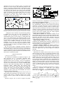
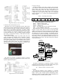
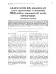
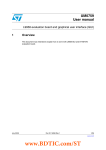
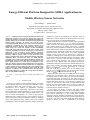
IEEE WCNC 2011 - Service and Application
Energy-Efficient Platform Designed for SDMA Applications in
Mobile Wireless Sensor Networks
Xiwei Zhang1,2
1
2
Guihai Chen1
Department of Computer Science, Nanjing University
Department of Computer and Information, Hohai University
Nanjing, Jiangsu, China
[email protected] [email protected]
Abstract — Although advance network planning and dense node
deployment, wireless sensor networks (WSNs) may achieve the
required performance, it still face the fundamental challenge of
meeting stringent power and time requirements using nodes with
limited sensing capacities. To better cope with the power
consumption problem, mobile sensor nodes can be introduced to
dynamically reconfigure the sensor network capacity in an
on-demand manner. Through data gathering and relaying,
mobile nodes can reduce the amount of data transmitting
between the static nodes then conserve the power of these nodes
to prolong the lifetime of network. In this paper we describe the
DataTruck, a new open-source sensing platform specifically
designed to support our experimental research in mobile sensor
networks, which is used to collect or relay data from static
sensors. The DataTruck node is designed around the S3C2440A
ARM920T RISC microprocessor and the IEEE 802.15.4
compliant CC2431 radio from Chipcon. Mobility is enabled with
an additional accessory board that allows the node to drive its 4
linear motion actuators. To reduce power consumption, a long
term sleep mode is supported through different power supplying
methods for main board and clock. Furthermore, we integrated
a smart antenna system to gather the data from multiple static
nodes concurrently which transmitting data using the same
frequency of channel. The experiments show that DataTruck
collects data efficiently to reduce the average data transmission
delay by using SDMA technology.
Keywords — wireless sensor networks; mobile sink; SDMA; smart
antenna
I.
INTRODUCTION
In recent year wireless sensor networks (WSNs) have been
used to monitor physical or environmental conditions, collect
or transmit sensing data. These networks can serve as an
infrastructure for a number of applications including
surveillance, medical monitoring, agricultural cultivation,
facility monitoring, and entertainments [1, 2]. For a number of
these applications, sensor nodes could be deployed in a vast
area or in harsh environments. As a result, a large network
deployment may require excessive sensor nodes in order to
achieve satisfactory sensing performance. Moreover, although
dense node deployment may initially achieve the required
performance, it does not adapt to dynamic changes of network
978-1-61284-254-7/11/$26.00 ©2011 IEEE
conditions or physical environments. For instance, death of
nodes due to battery depletion or physical attacks can easily
cause coverage holes in a monitored battlefield.
With recent advances in robotics and low power embedded
systems, mobile nodes [3, 4, 5, 6, 7, 8, 10] are becoming a
viable choice for the sensing applications mentioned above.
These mobile nodes may be mobile data ferries, or mobile
data relays, which responsible to collect or relay data from the
sensor nodes to base station. In this approach, a small number
of mobile devices referred to as data ferry roam about sensing
fields and collect data from sensors. As a result, significant
network energy saving can be achieved by reducing or
completely avoiding costly multi-hop wireless transmissions.
On the other hand, if the mobile node has sense ability, called
mobile sensor, it can cover more area than a stationary sensor
over a period of time because it can move to anywhere to
capture the event. Mobile nodes can promote the network
performance efficiently. We know for a random deployment in
static sensor networks, the sensor density should increase as
to provide -coverage in a network
with size of . In [3], authors prove an all mobile sensor
network can provide -coverage over the field with a constant
, independent of network size .
density of
Mobile Wireless Sensor Network (MWSN) can be mainly
divided into two categories. One is all nodes in the network
are mobile. However, these nodes only have limited mobility
to maintain the steady of network [5]. The other category is
widely researched that part of nodes in the network are mobile
and the other nodes are static, so the network is called hybrid
network. In this network, static nodes are responsible for data
sensing, and the mobile nodes move to them to collect or
relay the data to base station. A classical application of a
hybrid network is depicted in Figure 1.
In this paper, we design a mobile sink node named
DataTruck. Mobile sink usually has no sensing ability, so the
main function of DataTruck is collect or relay data from other
static sensors. DataTruck is a new sensor node platform
designed to support mobility experiments in sensor networks.
Although our design is driven by the research requirements of
our group, extra effort was taken during the design phase to
specify a feature set that is complimentary to existing
2089
platforms and can serve multiple aspects of research and
education in sensor networks. The DataTruck platform is built
around a S3C2440A ARM920T RISC microprocessor from
Samsung Semiconductor and a CC2431 radio with a 250kbps
raw data rate from Chipcon. The choice of the S3C2440A
microcontroller provides a wealth of peripherals and flexible
modes of operation. The Chipcon radio and its use with an
IEEE 802.15.4 compliant MAC protocol, make our node
interoperable with other sensor nodes available in the
community such as Telos and Micaz.
Fig. 2. The hardware design graph of main processing unit
Fig. 1. In this hybrid network, static nodes send data to rendezvous points
at first, and mobile node only needs to visit the rendezvous points to save the
data delay transmission for the moving trajectory of mobile node is shortened.
Although the above schemes can perform data gathering
in MWSN well, there still exist some disadvantages. For
example, when the DataTruck in the intersection area of
communication range of several nodes, it should gather data
one by one which increases the transmission delay. In this
paper, we improve the performance of data gathering in WSNs
by considering two critical factors: mobility and space-division
multiple access (SDMA) technique. To the best of our
knowledge, this is the first work that introduces SDMA
technique to mobile sink node design and explores the utility
of a joint design of mobility and SDMA technique in data
gathering schemes.
The rest of this paper is organized as follows. Section II
introduces hardware design of DataTruck and the compare of
other mobile nodes. In section III, we design a dual-antennas
system on DataTruck using smart antenna technology based on
SDMA. Section IV presents experiment and simulation results
and section V concludes the paper.
II. HARDWARE DESIGN
A. The core circuit board
The architecture of DataTruck is depicted in Figure 2. The
main processing unit is a S3C2440A ARM920T RISC
microcontroller [13]. We found this processor to be an
appealing choice since it provides a rich set of peripherals,
multiple power options and a suitable memory configuration.
The CPU core of S3C2440A is a 16/32-bit ARM920T RISC
processor which offers outstanding features. The ARM920T
implements MMU, AMBA BUS, and Harvard cache
architecture with separate 16KB instruction and 16KB data
caches, each with an 8-word line length. By providing a
complete set of common system peripherals, the S3C2440A
minimizes overall system costs and eliminates the need to
configure additional components.
Operating System and Communication Protocol Stack: To
make DataTruck interoperable with other devices, we ported
Chipcons IEEE 802.15.4 compliant medium access control
protocol which we operate inside the ARM Linux operating
system.
DataTruck Support API: In order to support the special
features of DataTruck we implemented a specialized protocol
that consists of the following modules:
Power Manager Module To support long term deep sleep we
have implemented a supervisor circuit outside the processor
operated by a real-time clock (RTC) with two interrupts. With
this circuit, the node has software control to transition into a
deep-sleep mode by disabling its main power supply regulator.
The RTC is directly powered by the batteries and not by the
on-board voltage regulator. This allows the RTC to keep track
of time with its own oscillator, when the voltage regulator
powering the rest of the board is disabled.
Device Drivers Module This component includes the low
level interfaces to all the devices and the I/O peripherals on the
DataTruck including the radio, the Real Time Clock, the ADC,
the UART, the timers and the DMA controller. Using this
module, applications can easily use all the devices connected
to the various I/O interfaces of the node.
Radio Manager Module This module is responsible for
configuring the communication subsystem. Applications can
call this component to change the transmission power level of
the radio and/or its security configuration.
Frequency Manager Module The frequency manager is
responsible for changing the operating clock frequency of the
node while preserving the correct timing of the operating
system, the Zigbee MAC layer and the application running on
the node.
B. The motor drive circuit
DataTruck uses L298P as motor circuit to drive its 4 linear
motion actuators. The L298 is an integrated monolithic circuit
in a 15-lead Multiwatt and PowerSO20 packages. It is a high
voltage, high current dual full-bridge driver designed to accept
standard TTL logic levels and drive inductive loads such as
relays, solenoids, DC and stepping motors. Two enable inputs
are provided to enable or disable the device independently of
the input signals. The emitters of the lower transistors of each
bridge are connected together and the corresponding external
terminal can be used for the connection of an external sensing
resistor. An additional supply input is provided so that the logic
works at a lower voltage. The motor drive circuit is depicted
in Fig.3.
The speed of motor is calculated using formula (1), which is
adjusted by controlling the PWM duty cycle through
programming. Suppose
is maximum rotation speed of
.
motor, duty cycle is , the average speed of motor is
(1)
In this formula,
is a duty-cycle.
is a value of
cycle of a timer, which is preset by the processor and is the
time of high level in the cycle which is set in the program to
.
satisfy
2090
D. Software design
In order to identify each node in mobile sensor network
which contains more than one mobile node and several static
sensor nodes, each node must have unique address and
specific transmitting format. The address of mobile node is
composed of a CC2431 code, which can be a fixed value, and
a node code. We assume the node code is an increasing
integer value like 0, 1, 2, 3 and etc. The transmitting format is
listed in Table 1.
Table 1. Transmitting format of nodes
#
Fig. 3. The schematic of motor drive circuit
C. Wireless RF communication circuit
DataTruck uses CC2431 (CHIPCON-CC2431, 2007) as the
control chip of wireless communication circuit. The CC2431 is
a true System-on-Chip (SoC) solution specifically tailored for
IEEE 802.15.4 and ZigBee applications. It enables ZigBee
nodes to be built with very low total bill-of material costs. The
CC2431 combines the excellent performance of the leading
CC2420 RF transceiver with an industry-standard enhanced
8051 MCU, 128 KB flash memory, 8 KB RAM and many
other powerful features.
The CC2431 is highly suited for systems where ultra low
power consumption is required. This is ensured by various
operating modes. Short transition times between operating
modes further ensure low power consumption. This is ensured
by various operating modes. Short transition times between
operating modes further ensure low power consumption. It
need less than 0.6μA current consumption in standby mode,
where external interrupts can wake up the system.
SurNo
DesNo
Length
data1
…
datan
CRC
#
The means of the notations in the table are as follows.
# — the message package is start and end with it
SurNo — address of source node
DesNo — address of destination node
Length — package size
datan — nth sensing data want to transmit to next node
CRC — cyclic redundancy check code
While DataTruck enters the sensing area it will send linking
requests to static nodes and set CC2431 in receiving mode.
Address resolution will be done if DataTruck received sensing
data correctly, otherwise it send a retransmission signal. When
the DesNo in the received package is matched with the
current DataTruck address, the package will be handled in the
local node. Otherwise, the DataTruck modifies the SurNo of
the package as the current DataTruck address and relay it to
the next node or base station. The data transmission workflow
is described in Fig.6.
Fig. 4. Appearance of CC2431
The picture of CC2431 is shown in Figure 4, and the
schematic of wireless RF communication circuit used in our
system is depicted in Figure 5.
Fig.6. The data transmission workflow
The photo of DataTruck is depicted in Figure 7 and the
comparison between DataTruck and other mobile nodes (such
as Robomote[7] and XYZ[8]) is listed in Table 2.
III.
Fig.5. Schematic of CC2431 in DataTruck
DESIGN OF MULTI-ANTENNAS ARRAY
A. SDMA
Space-Division Multiple Access (SDMA) is a channel
access method based on creating parallel spatial pipes next to
higher capacity pipes through spatial multiplexing and/or
diversity, by which it is able to offer superior performance in
radio multiple access communication systems.
2091
Table 2. Comparison between DataTruck and other mobile nodes
Parameters
CPU
DataTruck
ARM9
S3C2440A
Robomote
AVR Atmel
8535
Communication
CC2431
module
Number of motors
4
Maximum speed(cm/s)
130-180
Storage(K)
128
External Storage(M)
16
Data uploading speed
250
(kbps)
External A/D
yes
interfaces
Maximum running
10
time(hr)
Operation system
uc/os-II
ķXYZ is a node move along a string, so it
aspects.
XYZ
ARM7 OKI
ML67Q5002
UART
CC2420
2
15-20
1
0
ķ
ķ
32
2
192
250
no
yes
1
ķ
tinyos
SOS
cannot be compared in these
Fig. 7. A node of DataTruck
The kernel part of SDMA is smart antenna. Smart antennas
(also known as adaptive array antennas, multiple antennas and
recently MIMO) are antenna arrays with smart signal
processing algorithms used to identify spatial signal signature
such as the direction of arrival (DOA) of the signal, and use it
to calculate beamforming vectors, to track and locate the
antenna beam on the mobile target.
In SDMA system the beams are like multiple space division
channels. It provides a new domain, named space domain,
expect other three domains (time domain, frequency domain
and code domain). Although when the user is utilizing the
same frequency and address code in the same time, they can
use the space-division channels to promote the capacity of
communication system.
B. Design of dual-antennas system
In this paper, we are mainly consider the case when the
DataTruck is equipped with two antennas, because it is not
hard to mount two antennas on the DataTruck, while it will
likely become difficult and even infeasible to mount more
antennas due to the constraint on the distances between
antennas to ensure independent fading.
Now we will present the design of a smart antenna system
with dual-antennas. Smart antennas have two main functions:
DOA estimation and Beamforming. In this paper, smart
antenna achieves DOA and identifies the directions of the
received signals around the array antenna using the MUSIC
(Multiple Signal Classification) algorithm [10]. We control
the direction of the main beam by the LS-DRCMA (least
squares-de-spread re-spread constant module algorithm)
algorithm [11] and thus track the desired source signal, and at
the same time generate deep nulls in the direction of
interfering signals. Here we use dual FPGA and DSP chip to
design the smart antenna system, which is shown in Figure 8.
In Figure 8, the CORRELATE module in FPGA-B uses the
signal which is transmitted from FPGA-A after beamforming
to synchronize all signal data. The synchronization point is
delivered to DSP and the signal data is despreaded in
DEMODULE module and then is transmitted to DSP to
respread. The data after respreading is used to be the desired
signal for weight solving of Cholesky-LS module. Another
goal of these data is send to ERRORCODE_RATIO module
for solving the error data rate which is the parameter of the
state of system.
The sensing data from AD6645 were sent to DDC for wave
tracking which means the signal frequency will be nulled
from 40MHz after AD sampling. The signals will be
orthogonalized and sent to X_DPRAM module and DBF
module. X_DPRAM module translates these 4 line concurrent
data to 32-bit serial data and sends these data to DSP for
weight solving using EDMA mode through EMIFB interface.
The functions of DSP mainly include scheduling and
computing. For instance, in DSP there are some modules
which are used to control the synchronization state of system,
and regenerate the desired signal after respreading, etc. The
system needs initialization and the ResetFPGA( ) function is
called to set the parameters of FPGA. After initialization DSP
reads synchronization point and respreading data from
FPGA-A to determine whether the system is enter the
synchronization state. Then the DSP recalculate the weight
and update the weight value in the FPGA-B, and compute the
error code rate at the same time.
Fig. 8. The architecture of smart antennas system
C. Selection of compatible source nodes
Due to the smart antenna cannot null the interference which
in the same direction of desired signal, not any couple of
sensor nodes can send data to DataTruck. In order to revert to
the original data, the source couple of nodes should satisfy
certain conditions, which we call this couple of nodes is
compatible [12]. In this section, we use Linear Decorrelator
Strategy (LDS) to analyze this problem.
To guarantee that the decorrelator operation is successful,
we need to limit the number of simultaneous data streams to
no more than the number of receive antennas. In other words,
since the DataTruck is equipped with two receiving antennas,
at most two sensors can send data simultaneously to the
DataTruck. Figure 9 shows the transceiver architecture of
SDMA with the linear decorrelator. For simplicity, we will use
to denote
which represents the complex
channel coefficient vector (or called spatial signature)
and the two receive antennas of the
between sensor
DataTruck.
and
are the two columns of the channel
coefficient matrix . Suppose sensor 1 wants to send data
and sensor 2 wants to send data
. The received vector
at the DataTruck can be written as
2092
(2)
where
is channel noise.
We can see from Eq. (2) that each data stream faces an
extra source of interference from the other data stream. An
idea that can be used to remove this inter-stream interference
from an interested sensor is to project the received signal
onto the subspace orthogonal to the one spanned by the other
and
as the filter
channel vector. That is, we choose
vectors for sensor 1 and sensor 2, respectively, which satisfies
and
. Hence, the received signal can be
decoded as
(3)
After processed this way, the inter-stream interference
can be any vector that lies in
nulling can be achieved.
which is the space orthogonal to
, however, to maximize
the received signal strength,
should lie in the same
direction as the projection of
onto
.
should be
similarly chosen.
and
can be unit vectors because
increasing the length of them will not increase the SNR.
and
can be expressed as follows.
Fig. 9. Linear Decorrelator Strategy (LDS) in SDMA
IV.
EXPERIMENTS AND SIMULATIONS
To compare the proposed solution, we have made two kinds
of experiments to test the performance of DataTruck.
In the real experiments, we use DataTruck (with single
antenna) to gather data from static sensor nodes. There are 20
static nodes in the room, and DataTruck knows the position of
each node, it visits all nodes along a fixed trajectory and each
node is visited once in every round.
The DataTruck is equipped with an infrared ranging module
which is used to avoid the barrier. When DataTruck find the
barrier it will turn left or right with an angle of 30 degree,
then it will go to the position along prior direction using the
electronic compass module.
We compare the lifetime of network and the average data
transmission delay between using DataTruck and multihop
transmitting directly with different sensing frequency of static
nodes. The results are shown in Figure 10.
500
(4)
using DataTruck
no mobile sink
450
From Eq. (3), we can see that the signal part of
are
and
, respectively.
Lifetime of network(Minutes)
400
and
Since
and
, we can further
see that the projection operation always reduces the length of
unless
is already orthogonal to the spatial signature of
the other data stream. This is the overhead for nulling out the
would be in
interference. Hence, the effective channel for
deep fading whenever the projection of
onto
is small.
A similar situation is also applicable to
. Therefore, for
given transmission power of each sensor, not any two sensors
can successfully transmit data to DataTruck simultaneously.
To ensure the DataTruck can successfully decode the received
signal, the follow criteria should be satisfied
350
300
250
200
150
100
50
0
0
10
20
30
40
50
60
Number of sensing in 5 minutes
70
80
(a) sensing frequency VS. lifetime of network
80
using DataTruck
no mobile sink
70
60
where
,
,
and
are received
power and
of the received data from the two sensors,
respectively,
is denoted as the transmission power of each
sensor, and
is the receive sensitivity threshold while
is
the
threshold for the DataTruck to correctly decode
the received data. Any two sensors that satisfy this criteria can
successfully make concurrent data uploading to the DataTruck.
Such two sensors are said to be compatible [12].
Therefore, when we select the trajectory of DataTruck, the
position of compatible nodes should be took into
consideration to find the shortest path of DataTruck and
collect maximum size of data.
Average data delay(s)
(5)
50
40
30
20
10
0
0
10
20
30
40
50
60
Number of sensing in 5 minutes
70
80
(b) sensing frequency VS. average transmission delay
Fig. 10. The relationship between sensing frequency and lifetime
and average transmission delay
From Figure 10(a) we can see, while the frequency of data
sensing increases, the lifetime of network is reduced rapidly
with no mobile sink, because there are “hot spot” problem in
this network, the nodes near base station will die quickly for
2093
relaying all data transmitted from other nodes. In Figure 10(b)
the average transmission delay is not changed when using
DataTruck for data gathering, this is because the DataTruck
picks up data from all nodes when it moving along the
trajectory regardless of the frequency of data sensing.
We use simulations to verify the performance of DataTruck
with dual antennas. Suppose a sensor network with 40 static
nodes evenly distributed in 100×100 meter square field. There
are 30 data rendezvous points on the trajectory of DataTruck
which means in these rendezvous points there is at least one
pair of compatible nodes can send data to DataTruck. We
suppose the communication range of nodes is 30 meter and
the data amount of each node send to DataTruck is 1M bytes.
We analyze the performance of DataTruck through adjusting
the moving speed of it and the transmitting rate of static
sensor nodes, which is showed in Figure 11. The performance
is the average of the results in 1000 simulations.
V.
ACKNOWLEDGMENTS
The work is partly supported by China NSF grants
(60721002, 60825205, 61073152), the Fundamental Research
Funds for the Central Universities and Hohai Science Fund
grant (2009424211).
REFERENCES
[1]
2500
[2]
single antenna
dual antennas
Average Total Time(s)
2000
[3]
1500
[4]
1000
[5]
500
[6]
0
0
20
40
60
80
100
Number of Sensor Nodes
120
140 150
[7]
(a) moving speed is 0.5m/s; transmitting rate is 90Kbps
[8]
3000
single antenna
dual antennas
Average Total Time(s)
2500
[9]
2000
[10]
1500
[11]
1000
[12]
500
0
0
20
40
60
80
100
Number of Sensor Nodes
120
140 150
[13]
(b) moving speed is 1m/s; transmitting rate is 50Kbps
[14]
Fig. 11. The relationship between number of nodes and the
average total time of a data gathering
CONCLUSIONS
In this paper, we introduced the design and implementation
of DataTruck, a mobile sink node for data gathering which has
high performance. We have shown the software and hardware
design of DataTruck, and for the purpose of gathering data
efficiently, we design a smart antenna system on DataTruck.
Through experiments we can see that the mobile sink can save
the energy of the network, and with the dual antennas, it
reduces the average data transmission delay apparently.
From Figure 11 we can see that using dual antennas
systems outperform non-SDMA algorithm and the
improvement turns to be more evident when the network
becomes denser with more sensors. This is reasonable because
more sensors make data uploading time dominant and provide
more opportunities to utilize SDMA for concurrent data
uploading. Thus DataTruck with dual antennas is suitable for
data gathering when the density of sensor nodes is high. The
figure shows if there are 100 sensor nodes in the field, the
data delay is reduced 40% when the DataTruck using dual
antennas than single antenna.
2094
G. Tolle, J. Polastre, R. Szewczyk, D. Culler,et al. Amacroscope in the
redwoods. In ACM SenSys, pages51-63, 2005.
K. Mayer, K. Ellis, K. Taylor. Cattle health mon-itoring using wireless
sensor networks. In IASTEDCCN, 2004.
W. W. V. Srinivasan and K.-C. Chua. Trade-offs between mobility and
density for coverage in wireless sensor networks. In MobiCom, 2007.
G. Wang, G. Cao, and T. L. Porta, “Movement-assisted sensor
deployment.” in 23rd Annual IEEE Conference on Computer
Communications (INFOCOM), pp. 2469–2479, 2004.
S. Chellappan, W. Gu, X. Bai, D. Xuan, B. Ma, and K. Zhang,
“Deploying wireless sensor networks under limited mobility
constraints,” IEEE Transactions on Mobile Computing, vol. 6, no. 10,
2007.
Guoliang Xing, Tian Wang, Weijia Jia, and Minming Li, “Rendezvous
design algorithms for wireless sensor networks with a mobile base
station,”In MobiHoc, 2008.
K. Dantu, M. Rahimi, H. Shah, S. Babel, A. Dhariwal, and G. S.
Sukhatme. Robomote: enabling mobility in sensor networks. In IPSN,
2005.
D. Lymberopoulos and A. Savvides. Xyz: a motion-enabled, power
aware sensor node platform for distributed sensor network applications.
In IPSN, 2005.
S. R. Gandham, M. Dawande, R. Prakash, and S. Venkatesan, “Energy
efficient schemes for wireless sensor networks with multiple mobile
base stations,” In Globecom, 2003.
Liu wei, Li li, Zhang jin. Smart An tenna Design Ba sed on MUS IC and
LMS Algorithms. Electronic Sci.& Tech./Jan.15, 2009.
Wu Renbiao, Kang Xiao, Zhong Lunlong, Hu Tieqiao. Design and
Realization of Smart Antenna Based on DSP+FPGA. Journal of Civil
Aviation University of China. Vol.27,No.1, February 2009.
Miao Zhao, Ming Ma and Yuanyuan Yang. Mobile Data Gathering with
Space-Division Multiple Access in Wireless Sensor Networks. in 27rd
Annual IEEE Conference on Computer Communications (INFOCOM),
2008.
User’s manual of S3C2440A. TEXAS INSTRUMENTS, Samsung
Electronics. http://www.samsung.com/Products/Semiconductor/.
Intel
mote
(iMote).
http://www.intel.com/research/exploratory/motes.htm