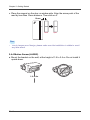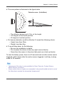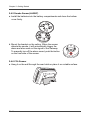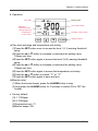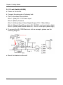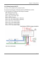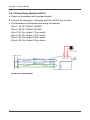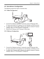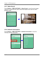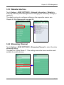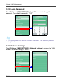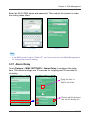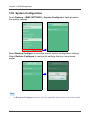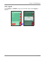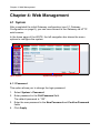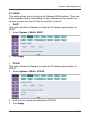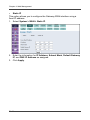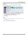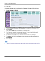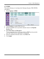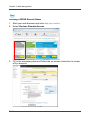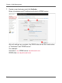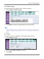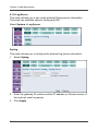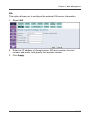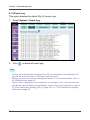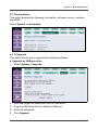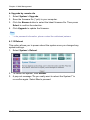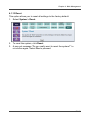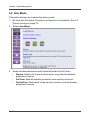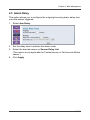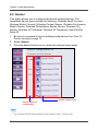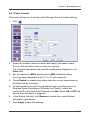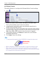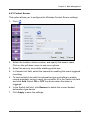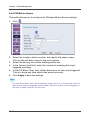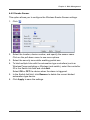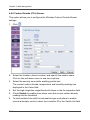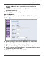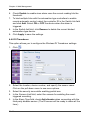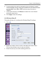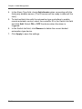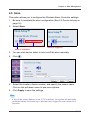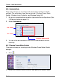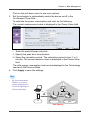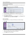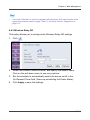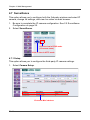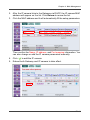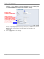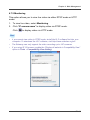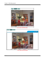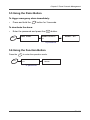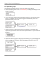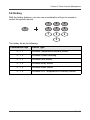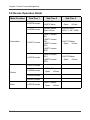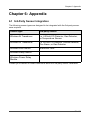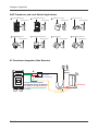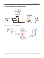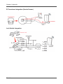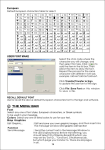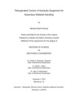
1
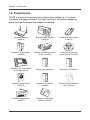
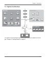
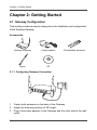
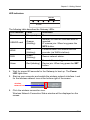
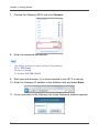
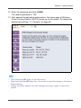
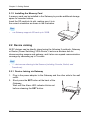
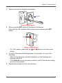
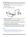
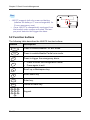
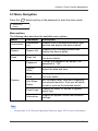
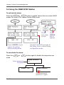
Wireless Home Security System User's Manual POW ER U SD C SB/ ARD SEN SOR S WAN PAN ALA RM SD CAR D Table of Contents Table of Contents Federal Communications Commission Interference Statement ........... 3 Safety Precautions .................................................................................... 4 Chapter 1: Introduction ............................................................................ 5 1.1 Features ....................................................................................................... 5 1.2 Products List ................................................................................................ 6 1.3 System Architecture ..................................................................................... 7 Chapter 2: Getting Started ....................................................................... 8 2.1 Gateway Configuration ................................................................................ 8 2.2 Device Joining ........................................................................................... 12 2.3 Device Deletion ........................................................................................... 15 2.4 On-Site Installation .................................................................................... 16 2.5 Surveillance Configuration ......................................................................... 29 Chapter 3: APP Management ................................................................. 31 Chapter 4: Web Management ................................................................. 56 4.1 System ....................................................................................................... 56 4.2 Arm Mode .................................................................................................. 72 4.3 Alarm Delay ............................................................................................... 73 4.4 Sensor ....................................................................................................... 74 4.5 Siren .......................................................................................................... 85 4.6 Automation ................................................................................................. 86 4.7 Surveillance ............................................................................................... 90 4.8 Notification ................................................................................................. 96 4.9 Security Zone ............................................................................................. 97 4.10 Logout ...................................................................................................... 98 Chapter 5: Panel Console Management ................................................ 99 Chapter 6: Appendix ............................................................................. 107 6.1 3rd-Party Sensor Integration .................................................................... 107 6.2 Troubleshooting ....................................................................................... 112 EN-2 FCC Statement Federal Communications Commission Interference Statement This equipment has been tested and found to comply with the limits for a Class B digital device, pursuant to Part 15 of the FCC Rules. These limits are designed to provide reasonable protection against harmful interference in a residential installation. This equipment generates, uses and can radiate radio frequency energy and, if not installed and used in accordance with the instructions, may cause harmful interference to radio communications. However, there is no guarantee that interference will not occur in a particular installation. If this equipment does cause harmful interference to radio or television reception, which can be determined by turning the equipment off and on, the user is encouraged to try to correct the interference by one or more of the following measures: • Reorient or relocate the receiving antenna. • Increase the separation between the equipment and receiver. • Connect the equipment into an outlet on a circuit different from that to which the receiver is connected. • Consult the dealer or an experienced radio/TV technician for help. Caution Any changes or modifications not expressly approved by the party responsible for compliance could void the user's authority to operate the equipment. This device complies with part 15 of the FCC Rules. Operation is subject to the following two conditions: (1) This device may not cause harmful interference, and (2) this device must accept any interference received, including interference that may cause undesired operation. FCC RF Radiation Exposure Statement 1.This Transmitter must not be co-located or operating in conjunction with any other antenna or transmitter. 2.This equipment complies with FCC RF radiation exposure limits set forth for an uncontrolled environment. This equipment should be installed and operated with a minimum distance of 20 centimeters between the radiator and your body. EN-3 Safety Precautions Safety Precautions When using this device, basic safety precautions should always be followed to reduce the risk of fire, electric shock and injury to persons, including the following: Safety Considerations • Do not place this device on an unstable cart, stand, or table. The device may fall, causing serious damage to it. • Place this device in a location that is close enough to an electrical outlet to accommodate the length of the power cord. • Place unit to allow for easy access when disconnecting the power cord of the device from the AC wall outlet. • Do not cover the device, or block the airflow to the device with any other objects. • Keep the device away from excessive heat and humidity and keep the device free from vibration and dust. • Keep liquids away from the device. • Do not expose the device to dripping or splashing. • Do not place objects filled with liquids, such as vases, on the device. • Do not overload the wall sockets, extension cords or adapter as this can result fire or electrical shock. • Disconnect the power plug from the AC outlet if the product is not being used for a long period of time. • To reduce the risk of fire or electric shock, install the device in a temperaturecontrolled indoor area free of conductive contaminants. • Operate this device only with the type of power source indicated on the device’s marking label. If you are not sure of the type of power supplied to your home, consult your retailer or local power company. Cleaning • Be sure to unplug the product before cleaning. • Wipe the device with a clean, dry cloth. • Do not use liquid, abrasive cleaners, waxes or solvents to clean the device. Servicing • Do not attempt to service this device yourself. Any attempt to do so will make the warranty invalid. • When servicing, refer to the qualified service personnel. EN-4 Chapter 1: Introduction Chapter 1: Introduction Congratulations on purchasing this Wireless Home Turnkey System (WHTS). WHTS provides a fully wireless solution that enables home user to secure, monitor and control home facilities by locally or remotely via phone, tablet PC, laptop, keypad and keyfob. The most important is – no professional installation required, it is far simpler than conventional home security systems (i.e. wired CCTV) which may require complex wiring or even re-construction. With the devices lying around your house, you can be very easily to construct a smart home by yourself. 1.1 Features WHTS supports the following features: • Burglar-Proof: Easy to set up the home security by full arm or partial arm, and maximum 10 security zones are allowed. • Anti-Disaster: Easy to prevent any disaster from happening at home by wireless. • Emergency Alert: Easy to trigger panic to alert family by a couple of handheld devices. • Real-Time Event Notification: Once any event be detected, the system will send out notifications by email or APP push per setup. • Home Automation: Easy to turn ON/OFF the home electronic appliances wirelessly to provide a smart living environment. • 3rd-Party Device Integration: Easy to integrate with the conventional sensors or devices by transducer or relay. • Energy Management: Easy to monitor the power consumption of home electronic appliance for energy saving. • Live View Video: Easy to watch the live video at Anytime and Anywhere by APP or Web interface. • Event-Triggered Recording: Easy to record the live video wirelessly once detected any event per setup. • Touch-n-Play Installation: Easy to deploy the whole security system by touch-n-play installation. • Internet Access: Provide the lite function of wireless AP to allow Internet access by wired or wireless. • APP Software (iOS / Android): Easy to operate via APPs. • APP Push Notification: Easy to receive notification by APP push. EN-5 Chapter 1: Introduction 1.2 Products List WHTS is a kind of turnkey security system by providing up to 14 items (including Gateway) as below. You may check out the product details by going through the respective chapter hereinafter. FA PA DA POW ER USB/ SD CARD SENS ORS WAN AWAY PAN ALAR M SD STA Y CAR D Wireless Gateway (LA5570) Wireless Panel Console (LA5572) Wireless Button Console (LA5573) Wireless Contact Sensor (LA5584) Wireless Pet Immune Motion Sensor (LA5582) Wireless Photoelectric Smoke Sensor (LA5587) Wireless CO2, Temperature & Humidity Sensor Wireless AI Transducer Wireless DI Transducer Wireless Alarm Switch (LA5576) Wireless Lock Switch (LA5580) Wireless Power Switching (AU) (LA5578) CO2 Monitor ALARM SET DO2 DO2 DI2 DO1 DO1 DI1 Reboot SET DI2 DI1 GND DC12V Wireless Relay Switch (LA5577) EN-6 Wireless Power Relay Module (LA5575) Chapter 1: Introduction 1.3 System Architecture For details on the installation and configuration about the respective device, see “Chapter 2: Getting Started” on page 8. EN-7 Chapter 2: Getting Started Chapter 2: Getting Started 2.1 Gateway Configuration This section provides a step-by-step guide to the installation and configuration of the Wireless Gateway. Accessories: POW ER USB/ SD CARD SENS ORS WAN PAN ALAR M SD CAR D Wireless Gateway Power adapter Stylus CD 2 Detachable antennas 2.1.1 Configuring Gateway Connection USB WPS USB LAN WAN SET DC IN 12V 1. Fasten both antennas on the back of the Gateway. 2. Adjust the antennas position at 90º angle. 3. Plug in the power adapter to the Gateway and the other side to the wall outlet. EN-8 Chapter 2: Getting Started LED indicators SENSORS POWER USB/ WAN SD CARD PAN ALARM The following table describes the Gateway LEDs: LED location Color Indication Power Blue (solid) Power on. USB/SD card Orange (blinking) Normal: SD card or USB disk drive is inserted. IP camera join: When long press the WPS button. WAN Blue (blinking) Communication via Internet service provider (via WAN interface). PAN Green (blinking) Sensor network status. Alarm Red (blinking) Normal: Alarm is triggered. Device join: When long press the SET button. 4. Wait for around 60 seconds for the Gateway to boot up. The Power LED lights blue. 5. Start up your computer and enable the wireless network interface. Look for the wireless network icon at the bottom right of the screen. wireless network icon 6. Click the wireless connection icon. Wireless Network Connection Status window will be displayed on the screen. EN-9 Chapter 2: Getting Started 7. Choose the Gateway SSID, and click Connect. 8. Enter the password and tap OK. Note • The default wireless network setting of the gateway: SSID: TECHview Password: (none) IP address: 192.168.19.254 9. Start your web browser. (It is recommended to use IE7.0 or above) 10. Enter the Gateway IP address in the Address field and press Enter. 11. Once connected to the Gateway, the Login Password window appears. EN-10 Chapter 2: Getting Started 12. Enter the password and click LOGIN. The default password is “123”. 13. After passed the password authorization, the home page of Wireless Home Turnkey System (WHTS) shows up on the screen. To change the appropriate settings, "4.1 System" on page 56.. Note • • • Short press the SET button to join the device. Press and hold the SET button for 15 seconds to reset all settings to the factory default settings. Unplug the power adapter from the Gateway and plug in again to reboot the system. EN-11 Chapter 2: Getting Started 2.1.2 Installing the Memory Card A memory card can be installed in the Gateway to provide additional storage space for recorded videos. Insert the SD card into its slot, making sure it is in the correct orientation as shown in the illustration. Note • The Gateway supports SD card up to 32GB. POWE R USB SD CA / RD SEN SORS WAN PAN ALAR M SD CARD 2.2 Device Joining All RF devices can be directly joined using the following 2 methods: Gateway or Router (Power Switching). With Router, it acts as a wireless hub for interconnecting sensors and gateway, and it also can expand communication coverage by cascading up to 3 routers. Note • RF devices are referring to the Sensors (including Console, Switch, and Transducer). 2.2.1 Device Joining via Gateway 1. Plug in the power adapter to the Gateway and the other side to the wall outlet. 2. Short press the SET button at the back of the Gateway. Wait until the Alarm LED indicator blinks red before releasing the SET button. USB WPS USB LAN WAN EN-12 DC IN 12V SET Chapter 2: Getting Started 3. Remove the sensor bracket if necessary. bracket SET Wireless Contact Sensor 4. Short press the SET button at the back of the sensor. Wait until the LED indicator blinks green before releasing the SET button. LED Wireless Contact Sensor • For CO2 sensor, press both the and buttons until the screen blinks. 5. To verify if the device binding process is successful, do one of the following: • Wait for few seconds until both indicators (on the Gateway and device) turned off. • Click Refresh icon on the web console to verify if the device binding process is successful. 6. Repeat above steps to bind other devices. EN-13 Chapter 2: Getting Started 2.2.2 Device Joining via Router (Power Switching) 1. Plug in the power switch to the wall outlet. 2. Short press the SET button on the power switch. Wait until the LED indicator blinks green before releasing the SET button. 3. Remove the sensor bracket if necessary. 4. Short press the SET button at the back of the sensor. Wait until the LED indicator blinks green before releasing the SET button. • For CO2 sensor, press both the and buttons until the screen blinks. LED Wireless Contact Sensor 5. To verify if the device binding process is successful, do one of the following: • Wait for few seconds until both indicators (on the router and device) turned off. • Click Refresh icon on the web console to verify if the device binding process is successful. 6. Repeat above steps to bind other devices. EN-14 Chapter 2: Getting Started 2.2.3 Checking Device Received Signal Strength Indication (RSSI) Short press the SET button at the back of the sensor twice. The signal strength is indicated by its LED indicator. Status LED Color and Behavior Good Blinks green (very quickly) for 15 seconds. Normal Blinks green (quickly) for 15 seconds. Poor Blinks green (slowly) for 15 seconds. (not recommended) No Signal Blinks red for 3 seconds and then turns off. (not recommended) Note • RSSI devices are including Button Console, Contact Sensor, Motion Sensor, Smoke Sensor, AI Transducer, DI Transducer, and Siren. 2.3 Device Deletion 2.3.1 Device Deletion To remove the device binding, press the SET button for 5 seconds. The LED indicator blinks green and then turns off. After few seconds, the LED indicator blinks red and then turns off again, indicating the deletion process is complete. You can also remove the device binding on the web console. However, it is only applicable for non-battery-power device. • For CO2 sensor, press both the button until the screen blinks. 2.3.2 Reboot the Gateway Unplug the power adapter from the Gateway and plug in again to reboot the system. 2.3.3 Reset the Gateway Press and hold the SET button for 15 seconds to reset all settings to the factory default settings. EN-15 Chapter 2: Getting Started 2.4 On-Site Installation 2.4.1 Panel Console (LA5572) a. Mount the bracket on the wall. b. Open the battery cover and install the batteries into the battery compartments. Then close the bottom cover firmly. Note • • The battery is designed for power backup and it will last for 2 hours. The tamper-proof function will only be activated after the system is armed. 2.4.2 Button Console(LA5573) a. Follow the steps to change the battery. (Attention: CR2032 battery positive side up) SET Remove the 4 screws and the back cover EN-16 3V SET 3V 3V Install the battery Replace the back cover and attach the 4 screws Chapter 2: Getting Started b. Button functions FA Button Press Long press (3 seconds) FA Full Arm Panic PA Partial Arm On* DA Disarm Off* PA DA * It needs to set up the link device to make the function buttons work. 2.4.3 Contact Sensor(LA5584) a. Install the battery into the battery compartment. (Attention: CR2032 battery positive side up) b. Mount the bracket on the frame side of the door or window, and then put the reed on the bracket. 38mm 28mm EN-17 Chapter 2: Getting Started c. Place the magnet on the door or window side. Align the arrow point of the reed by less than 10mm distance. Then stick on it. 10mm Close Open Note • Due to tamper-proof design, please make sure the installation is stable to avoid any false alarm. 2.4.4 Motion Sensor(LA5582) a. Mount the bracket on the wall, at the height of 1.8 to 2.4 m. Do not install it upside down. 1.8~2.4m EN-18 Chapter 2: Getting Started b. The scan pattern is illustrated in the figure below. 80 70 Detection area : (Unit=Meter) 60 50 40 30 20 (M) A B 10 0 2 10 2m 1 20 0 30 1 2 3 4 5 6 7 8 9 B10 11 12 13 A (M) Distance:10m 40 50 60 80 70 (M) 0 1 2 3 4 5 6 7 8 9 10 11 12 13 • The effective distance is 8~10m, at 2m height. • 150-degree at horizontal position. • 25-degree at vertical position. c. Pet immune detection could be effective if it meets the following criteria: • Height: less than 50cm. • Weight: less than 6kg. d. To avoid false alarm, do the following: • Be sure the installation is stable. • Do not place the device to face any light source directly. • Never face the sensor to the place that pests can climb up directly. To save the battery power, there is a 30 seconds lock-out after motion sensor triggered; which means after the motion sensor triggered, it will stay in sleep mode for 30 seconds. Note • • Tamper-proof function is only available for Panel Console, Contact Sensor, Motion Sensor, and Siren. Alarm switch (siren) is highly recommended to be joined/installed at last to avoid the false alarm caused by unexpected tamper-proof. EN-19 Chapter 2: Getting Started 2.4.5 Smoke Sensor(LA5587) a. Install the batteries into the battery compartments and close the bottom cover firmly. b. Mount the bracket on the ceiling. When the sensor detects the smoke, it will automatically trigger the alarm and also send out the signal to the Gateway. To manually turn off the alarm sound, push the button on the front side of the sensor. 2.4.6 CO2 Sensor a. Hang it on the wall through the rear holds or place it on a stable surface. EN-20 Chapter 2: Getting Started b. Operation: Fan state Backlight: Green (normal) / Orange (warning) Temperature current value Buzzer state CO2 current value Humidity current value Setting buttons (a)Two level warnings and temperature unit setting: (1)Press the SET button once to access the level 1 (L1) warning threshold setup. (2)Press the or button to increase or decrease the setting value, 100ppm per time. (3)Press the SET button again to access the level 2 (L2) warning threshold setup. (4)Press the or button to increase or decrease the setting value, 100ppm per time. (5)Press the SET button again to access the temperature unit setup. (6)Press the or button to switch “°C” or “°F”. (7)Press the SET button again to save and exit. (b)Buzzer setup: (1)When the buzzer beeps, press the ALARM button to stop. (2)Long press the ALARM button for 3 seconds to switch ON or OFF the buzzer. c. Factory default: (1)L1: 1200ppm (2)L2: 2000ppm (3)Temperature unit: °C (4)Buzzer beeps: ON EN-21 Chapter 2: Getting Started 2.4.7 Alarm Switch (LA5576) a. To power on the device, do one of the following: i. Plug in the power adapter to the device and the other side to the wall outlet. ii. Insert the batteries into the device. To insert the batteries, refer to the illustration below b. Once the alarm is triggered, the alarm volume is approximately 90dB. To turn off the alarm sound, press the upper LED button. EN-22 Chapter 2: Getting Started 2.4.8 Power Switching(LA5578) a. Plug it into a wall socket and connect to any household appliance with less than 10A. b. Press the ON/OFF button to manually turn on/off the power relay. c. Power Meter: Plug the home appliance on LA5578. It can calculate the Voltage(V), Current(A), Power(W), Frequency(Hz) when the device is power ON. (the minimum Watt should be powered on for at least 1 hour) d. Energy Used Cost: Input the unit cost at peak time and off-peak time by Web Management first and select the accumulate period (by month, the maximum is 3 months). Then the system will automatically calculate the Total Cost, Peak Time Cost, and Off-Peak Time Cost. (the earliest period is 1 year ago) e. The power meter value can be displayed on the Web Management, APP, and Panel Console(LA5572). However, the cost value can only be displayed on the Web Management and APP. EN-23 Chapter 2: Getting Started The following devices are designed to be integrated with the 3rd party sensor once required. Please refer to "Chapter 6: Appendix" on page 107. for more details. 2.4.9 Analog Input (AI) Transducer a. Power on the device. b. Connect the wiring pin of 3rd party device by 4~20mA signal. c. The Pin functions are as below: Wire 1- (Red) DC 5~12V Power Input Wire 2- (Black) Common & Negative 4-20mA Signal Input Wire 3- (Yellow) Positive 4-20mA Signal Input Wire 4- (Green) Reserved Wire 5- (White) Reserved d. To connect the GTF200-FL Gas detector as example, please see the following diagram: DC12v Adapter B F R DC POWER SUPPLY 24-30 VDC (for instrument) G Legend and Description B: Negative wiring of detector R: Positive wiring of detector G: Analog wiring of detector F: Fuse AI Transducer Red Black Yellow 4-20mA Current e. Mount the bracket on the wall. f. When configuring the detective range, the high range value is 20mA and the low range value is 4mA (4~20mA). The threshold value will be set based on percentage. (for example: when 20mA setting as 50, 4mA setting as 10; if the threshold value setting as 40, that means the device will be triggered while the current value over 16mA.) (1)Signal current: 4mA (2)Setting value: 10 EN-24 16mA 20mA 40 50 Chapter 2: Getting Started 2.4.10 Digital Input (DI) Transducer a. Install the battery into its compartment. (Attention: CR2032 battery positive side up) T SE 3V Remove the 3 screws Remove the back cover Install the battery. Then replace the back cover and attach the 3 screws. b. Connect the wiring pin of 3rd party device by DI/DO (dry contact). c. The Pin functions are as below: Wire 1- (Red) Dry contact Input (Positive) Wire 2- (White) Dry contact Input (Negative) d. To connect the CX-96R CO detector as example, please see the following diagram: e. Mount the bracket on the wall. EN-25 Chapter 2: Getting Started 2.4.11 Lock Switch(LA5580) a. Power on the device. b. Connect the wiring pin of 3rd party lock. c. The Pin functions are as below: Wire 1- (Red) DC +12V Power Input Wire 2- (Black) Common Wire 3- (Yellow) Open Collect Digital Output (12V / 120mA Max.) Wire 4- (Green) Open/Close status 0V, 12V DC Level input (active high) Wire 5- (White) Lock/Unlock status 0V, 12V DC Level input (active high) d. To connect the SL-130B Electronic lock as example, please see the following diagram: e. Mount the bracket on the wall. EN-26 Chapter 2: Getting Started 2.4.12 Relay Switch(LA5577) a. Power on the adapter with a proper location. b. Connect the wiring pin of 3rd party device by DI/DO (dry contact). c. The description of integration and wiring as example: SET: blinking when joining Reboot: blinking when reboot Wire 1- DC +12V: Power Input Wire 2- GND: Common Wire 3- DI1: Dry contact Input 1 (Positive) Wire 4- DI2: Dry contact Input 2 (Positive) Wire 5- DO1: Dry contact Output Wire 6- DO1: Dry contact Output Wire 7- DO2: Dry contact Output Wire 8- DO2: Dry contact Output *hard buttons: DI/DO for trigger simulation *NFB: No-Fuse Breaker EN-27 Chapter 2: Getting Started 2.4.13 Power Relay Module(LA5575) a. Power on the adapter with a proper location. b. Connect the wiring pin of 3rd party device by DI/DO (dry contact). c. The description of integration and wiring as example: Wire 1- AC IN: 100VAC~240VAC Wire 2- AC IN: 100VAC~240VAC Wire 3- K1: Dry Output 1 Dry contact Wire 4- K1: Dry Output 1 Dry contact Wire 5- K2: Dry Output 2 Dry contact Wire 6- K2: Dry Output 2 Dry contact *NFB: No-Fuse Breaker EN-28 Chapter 2: Getting Started 2.5 Surveillance Configuration This Gateway supports the types of camera setup. 2.5.1 Wired Configuration USB WPS USB LAN WAN SET DC IN 12V UTP 1. Connect the Gateway and the IP camera by using an Ethernet cable. IP camera will obtain an IP address from the Gateway via DHCP protocol. 2. To obtain the IP camera MAC address and configure related IP camera settings, refer to "4.7 Surveillance" on page 90.. 3. Reboot both Gateway and IP camera to take effect. 2.5.2 Wireless Configuration WiFi USB WPS USB LAN WAN SET DC IN 12V 1. Connect the Gateway and the IP camera by using an Ethernet cable. IP camera will obtain an IP address from the Gateway via DHCP protocol. 2. To obtain the IP camera MAC address and configure related IP camera settings, refer to "4.7 Surveillance" on page 90.. EN-29 Chapter 2: Getting Started 3. Enable IP camera wireless function then select the Gateway as an access point (AP). 4. Disconnect the Ethernet cable. Then reboot both Gateway and IP camera to take effect. 2.5.3 Wireless via WPS Configuration WPS WPS USB WPS USB LAN WAN SET DC IN 12V 1. Make sure your WLAN security type is WPA. Refer to "4.1.4 WLAN" on page 60. for more details. 2. Click the WPS button of IP camera, then click the WPS button of the Gateway for 3 seconds to start WPS pairing process. IP camera will obtain an IP address from the Gateway via DHCP protocol. 3. To obtain the IP camera MAC address and configure related IP camera settings, refer to "4.7 Surveillance" on page 90.. 4. Reboot both Gateway and IP camera to take effect. 5. If the WPS pairing process is failed, reset the IP camera to its default settings and try it again. If the problem persists, connect the IP camera to the Gateway either using Wired or Wireless Configuration method. Note • • • The IP default range: 192.168.19.60~99 is reserved for IP camera. For details on the 3rd-party IP camera setup, please refer to its user manual. It is highly recommended to install VLC media player (v1.1.9 or above) on your PC before displaying the video of IP camera via HTTP browser. EN-30 Chapter 3: APP Management Chapter 3: APP Management 3.1 Download APP on Smart Handheld Device By using APP, you can view the sensors status, video live view, and access the Web Management remotely to monitor your home and family at anytime and anywhere. Note • The user interface varies depending on your smart handheld device design. 3.1.1 Installing Application (iOS) Recommended environment: • iPhone 4 or above / iPad2 or above • iOS 6.1 or above 1. Download the APP (TECHView Home Auto) from App Store. 2. Install the application. 3.1.2 Installing Application (Android) Recommended environment: • Android phone CPU 1 GHz or above, with Duo core • Android 4.0 or above 1. Download the APP (TECHView Home Auto) from Google Play. 2. Install the application. EN-31 Chapter 3: APP Management 3.2 Network Setting For Wi-Fi connection (local use), set your phone Wi-Fi setting to connect to the gateway’s SSID. Once connected, you may have to enter the encryption key once required. Note • • Default SSID is “TECHview” and no encryption key. For mobile network user (3G or above), skip this network configuration. 3.3 Launch APP Touch the APP icon ( EN-32 ) to launch the APP. Chapter 3: APP Management 3.4 Login Page 1. Touch the APP icon ( ) to enter the login page. 2. Enter the Gateway “Domain Name or IP” and “Password” to login. Note • You may turn on “Remember Password” function to retain the password for the next time login. The default is “123”, same as WebUI. 3.5 IP Detection and Selection If Internet link is connected, the APP will automatically detect WAN IP. To select the detected WAN IP, swipe down the screen as shown in the illustration below. EN-33 Chapter 3: APP Management Once the system detects any changes on the WAN IP, the APP will push a message to notify user. User may enter the specific IP / Gateway Domain Name directly. 3.6 Push Notification Setting (iOS) When first time login the APP, it will automatically register the push notification service and enable the function automatically. If you do not want to receive the push notification, set the Settings > Notifications Center setting to “None” to disable the function. EN-34 Chapter 3: APP Management 3.7 Push Notification Setting (Android) When first time login the APP on an Android device, a pop-up message appears on the screen to confirm if you’re allowed to turn on the push notification service. Click YES to continue. Check to enable Wait for a while to let the system receives the information from the cloud server You can also configure the Push Notification at “MISC SETTINGS”. EN-35 Chapter 3: APP Management 3.8 Push Notification When some events are detected, the gateway will automatically send out the push messages to your smart handheld device in minutes, even when the APP is off-line. Current notification Several notifications (unread) 3.9 Main Page Refresh Options Function bar Panic Partial Arm Full Arm Disarm (Display only at Arm/ Stay/ Alarm) The current devices status is indicated by its color. • Red means normal, • Green means triggered/on On iPhone, push the Home button to switch to desktop. The APP is still running in background. EN-36 Chapter 3: APP Management 3.10 Panic Touch and hold the Panic icon (shown on the function bar) for a few seconds, then it will trigger alarm immediately. 3.11 Arming/Disarming Touch the Arm/Stay or OFF icon to arm or disarm the system. Main page Full Arm mode Partial Arm mode EN-37 Chapter 3: APP Management 3.12 Sensor State Error While arming, the system will check all contact sensors’ state first and display an error message if any of the sensor is detected in “open” state. 3.13 Alarm Trigger Once any alarm is triggered, a pop-up message will appear on the screen, the system will send out a push message to your smart handheld device, and all related device icons will change to Green color to alert. If the alarm has been triggered (i.e. 30 minutes ago), the related sensor icons remain in Green until the state is changed back (click “OFF” on APP). EN-38 Chapter 3: APP Management 3.14 Refresh Click the Refresh icon to manually refresh all status immediately. Refresh The auto refresh timer is approximately 5~15 seconds by default. If you quick-click the Refresh icon for three times, the system will pop-up the “Prompt” window to confirm the connection. EN-39 Chapter 3: APP Management 3.15 Rename Touch and hold the desired device icon and the rename dialog box appears on the screen. Enter the new name using the on-screen keyboard. You may also customize the name in any language (i.e. Chinese) supported by your smart handheld device. 3.16 Device Information Select and touch the device icon once, the screen will display the device information, which includes device type, device ID/name, zone, switch link, camera link, and its current value. EN-40 Chapter 3: APP Management 3.17 Relay Detail Relay Switch and Power Relay Module are DI/DO device types. Click it to see the setup detail. Relay Switch Relay Switch Power Relay Module 3.18 Switch On/Off For automation-type controllers (such as Wireless Power Switching or Wireless Lock Switch), you can manually turn on/off the device switch. EN-41 Chapter 3: APP Management Select and touch the switch device icon once, then slide it to turn ON or OFF. <Power Off> <Power On> Siren can be turned ON or OFF randomly by touching the “Siren” icon. 3.19 Current Power Status When power switching is turned on, the current measured value will show voltage, current, power, and frequency. Touch it to enlarge the display. 3.20 On-Demand Timer Touch On-Demand Timer to select the power on timer. EN-42 Chapter 3: APP Management Select Schedule to set the schedule to let the device to automatically turn the switch on/off. 3.21 Schedule Setup You can set up to 2 schedules per day. Set the desired schedule to ON and touch to access the time and day setup. Specify the Start and End time, then select the desired day. <Slide to enable> <Scroll to select> <Tick to select> EN-43 Chapter 3: APP Management 3.22 Power Meter and Cumulative Usage Touch Usage to select the cumulative period to calculate. The total spent energy and cost will be displayed. <Scroll to select> The maximum cumulative period is 3 months, and the earliest month shown on the screen is 12 months ago. EN-44 Chapter 3: APP Management 3.23 Video Live View Select and touch IP camera’s icon to display the live video. To view the live image of any camera on full screen, hold your smart handheld device horizontally for better viewing. Full screen Normal view 3.24 Taking Screenshot For iPhone/iPad, press both Power and Home buttons to capture a screenshot of the current screen. On most Android phones, press both Power and Volume Down buttons to capture a screenshot of the current screen. Full screen EN-45 Chapter 3: APP Management 3.25 Device Disconnected The device icon will be showed in GREY once disconnected from the Gateway. If this happens, check if the power supply is unplugged or the battery power is low on each disconnected sensor. 3.26 Options Touch Options (on the top-left) to show the sub-function page. EN-46 Chapter 3: APP Management 3.27 Zone Setup Touch Zone Settings to enter the zone setup page. icon will appear on You may choose the zone name, devices to apply (the the screen), and enable the specific zone will be armed while Partial Arming. <Select link device(s)> <Specify zone name> <Slide to enable> <Scroll to select location> To customize the zone name, select Other and enter the desired zone name. EN-47 Chapter 3: APP Management 3.28 Switch Link Touch Switch Link to configure the link setup. Select the sensor first, then select the switch to link, up to 5 switches. The icon will appear on the screen. • By default the switch is set to ON. A red power icon ( ) at the right-bottom indicates the power is on. To turn off the switch, click the icon. The red power icon ( ) will disappear. • To cancel the selection, tap the desired switch. Touch OK to confirm. Linked switches EN-48 Chapter 3: APP Management 3.29 Camera Link Touch Camera Link to configure the camera setup. Select the camera first, then select the sensor to link. The on the screen. Touch OK to confirm. icon will appear Linked sensors 3.30 System Log Touch Options > MISC SETTINGS > System Log to view the latest event log stored in the Gateway. EN-49 Chapter 3: APP Management 3.31 Video Event Touch Options > MISC SETTINGS > Video Event to view the event-trigger video list. To play back the video, select the desired event and the video playback starts. Full screen Event-trigger video list 3.32 Network Information Touch Options > MISC SETTINGS > Network Information to view the Gateway network information. EN-50 Chapter 3: APP Management 3.33 Website Interface Touch Options > MISC SETTINGS > Network Information > Website to enter the Gateway Web Management for changing the necessary settings (if required). The details on how to configure settings on the respective sensor, see Chapter 4: Web Management on page 56. 3.34 Streaming Channel Touch Options > MISC SETTINGS > Streaming Channel to select the video streaming setting. The default is “Video Steam 2”. This setting means the lower resolution and suitable for mobile devices. EN-51 Chapter 3: APP Management 3.35 Login Password Touch Options > MISC SETTINGS > Login Password to change the password. The default password is “123”. Note • The password must be at least 3 numeric characters. The maximum password length is 12. 3.36 Network Settings Touch Options > MISC SETTINGS > Network Settings to change the WAN mode. The default setting is “DHCP”. EN-52 Chapter 3: APP Management Enter the Wi-Fi SSID name and password. Then reboot the system to make the setting takes effect. PPPoE DHCP Note • If the WAN mode is set to “Static IP”, you have to access the Web Management to change the network setting. 3.37 Alarm Delay Touch Options > MISC SETTINGS > Alarm Delay to configure the delay time. The default settings are 10 seconds for outgoing and 30 seconds for incoming. Drag the bar to select the time Select which devices are on the delay list EN-53 Chapter 3: APP Management 3.38 System Configuration Touch Options > MISC SETTINGS > System Configure to backup/restore the system settings. Select Backup Configure to save the current system configuration settings. Select Restore Configure to restore the settings that you have saved earlier. Note • The Restore Configure function will only available when there is a backup data. EN-54 Chapter 3: APP Management 3.39 Logout Touch Options > LOGOUT to log out of the APP. Then touch Logout to confirm. EN-55 Chapter 4: Web Management Chapter 4: Web Management 4.1 System After completed the initial Gateway configuration (see 2.1 Gateway Configuration on page 8), you can now connect to the Gateway via HTTP web browser. In the home page of the WHTS, the left navigation bar shows the menu options to configure the system. Menu option System setting/status 4.1.1 Password This option allows you to change the login password. 1. Select System > Password. 2. Enter password in the Old Password field. The default password is “123”. 3. Enter the new password in the New Password and Confirm Password fields. 4. Click Apply. EN-56 Chapter 4: Web Management 4.1.2 WAN This option allows you to configure the Gateway WAN interface. There are three available options. Depending on what internet service provider you choose, you can use one of them to connect to Internet. • DHCP This option allows the Gateway to obtain an IP address dynamically via DHCP. 1. Select System > WAN > DHCP. 2. Click Apply. • PPPoE This option allows the Gateway to obtain an IP address dynamically via PPPoE. 1. Select System > WAN > PPPOE. 2. Enter the user name and password of PPPoE. 3. Click Apply. EN-57 Chapter 4: Web Management • Static IP This option allows you to configure the Gateway WAN interface using a fixed IP address. 1. Select System > WAN > Static IP. 2. Enter the information for IP Address, Subnet Mask, Default Gateway IP, and DNS IP Address as assigned. 3. Click Apply. EN-58 Chapter 4: Web Management 4.1.3 LAN This option allows you to configure the Gateway LAN interface. 1. Select System > LAN. 2. Enter IP Address and Subnet Mask as your preferred. The default IP address is “192.168.19.254”. 3. Click Apply. Note • Here below is the default fixed assignment for the last field of IP address (i.e. xx.xx.xx.60) a. 60 ~ 99 is reserved for IP camera use. b. 100 ~ 253 is reserved for DHCP client use. EN-59 Chapter 4: Web Management 4.1.4 WLAN This option allows you to configure the Gateway Wireless LAN interface. 1. Select System > WLAN. 2. Check Enable Wireless LAN Interface to enable the Wireless LAN. 3. Enter SSID. The default SSID for the Gateway is “TECHview”. 4. On Channel, specify the wireless channel. To avoid conflicting with other access points, set the setting to Auto. 5. On Wireless LAN Security, select the desired security settings. 6. To enable WEP/WPA encryption, enter the key for data encryption in Auth Mode. 7. Click Apply. Note • If the WPS function is being used, the WLAN security type must be set to WPA. EN-60 Chapter 4: Web Management 4.1.5 DDNS This option allows you to configure the Gateway Dynamic DNS (DDNS) information. 1. Select System > DDNS. 2. Check Enable to enable DDNS Service. 3. Select the DDNS service provider’s domain name in the Dyndns System field. 4. Enter Username and Password. The account information will be provided by DDNS service provider once the DDNS service registration is completed. 5. Enter the registered domain name in the Alias field. 6. Click Apply. EN-61 Chapter 4: Web Management Note Creating a DDNS Domain Name 1. Start your web browser and enter http:dyn.com/dns. 2. Select Devices Remote Access. 3. Fill in the necessary data and follow the on-screen instruction to create a Dyn account. EN-62 Chapter 4: Web Management 4. Enter the confirmation code to confirm your account. Note • A confirmation code will be sent to your e-mail account. 5. Click PROCEED TO CHECKOUT to continue. 6. Fill in the payment information and click PLACE ORDER. Note • You will be given a 14-day free trial and you can cancel the application within the trial period. The payment will only be charged after the free trial. EN-63 Chapter 4: Web Management 7. Create a new hostname and click Activate. Enter a hostname and IP address and select a DDNS server. After all settings are complete, the DDNS alias will be the combination of “hostname” and “DDNS server”. For example: Hostname: xxx; DDNS server: dyndns-web.com DDNS alias: xxx.dyndns-web.com EN-64 Chapter 4: Web Management 4.1.6 DHCP Leasing This option displays the Gateway DHCP client information. 1. Select System > DHCP Leasing. 2. Click Renew to renew the Gateway DHCP client information. Note • The first IP address shown on the above illustration as “Always” belongs to an IP camera. To configure IP camera setup, refer to 4.7 Surveillance on page 90 for details. 4.1.7 Clock This option allows you to adjust the current system date and time. 1. Select System > Clock. 2. Enter the new Date and Time as required. 3. Click Apply. EN-65 Chapter 4: Web Management 4.1.8 Log Server This option allows you to set up the external Syslog server information. There are two available options: Syslog and SIA. Select System > Log Server. Syslog This option allows you to configure the external log server information. 1. Select Syslog. 2. Enter the gateway ID number and the IP address (or Domain name) of the external event log server. 3. Click Apply. EN-66 Chapter 4: Web Management SIA This option allows you to configure the external SIA server information. 1. Select SIA. 2. Enter the IP address or Domain name, SIA port number, Account number and prefix, and specify the receiver number. 3. Click Apply. EN-67 Chapter 4: Web Management 4.1.9 Event Log This option displays the latest fifty (50) event logs. 1. Select System > Event Log. 2. Click to delete all event logs. Note • • • All logs are automatically saved into the SD card installed on the Gateway. (50 logs per file and more than 1,000 logs could be saved). All logs can also be sent via a designated e-mail. For more information, refer to 4.8 Notification on page 96. Alarm, Panic, Tampered, Lost connection, Low battery, Over current protection logs will be sent via APP push notification service. For more information, refer to 3.6 Push Notification Setting (iOS) on page 35 or 3.7 Push Notification Setting (Android) on page 36. EN-68 Chapter 4: Web Management 4.1.10 Information This option displays the Gateway information (software version, network, and SSID). Select System > Information. 4.1.11 Upgrade This option allows you to upgrade the Gateway software. a. Upgrade by USB pen drive 1. Select System > Upgrade. 2. Save the image file (whss.pck) into the USB drive. 3. Plug the USB drive into the Gateway USB port. 4. Enter the password. 5. Click Upgrade. EN-69 Chapter 4: Web Management b. Upgrade by remote site 1. Select System > Upgrade. 2. Save the firmware file (*.pck) to your computer. 3. Click the Browse button to select the latest firmware file. Then press Select to confirm the selection. 4. Click Upgrade to update the firmware. Note • For the password information, please contact the authorized partners. 4.1.12 Reboot This option allows you to power reboot the system once you changed any system settings. 1. Select System > Reboot. 2. To reboot the system, click Reboot. 3. A pop-out message “Do you really want to reboot the System?” to re-confirm again. Select Yes to proceed. EN-70 Chapter 4: Web Management 4.1.13 Reset This option allows you to reset all settings to the factory default. 1. Select System > Reset. 2. To reset the system, click Reset. 3. A pop-out message “Do you really want to reset the system?” to re-confirm again. Select Yes to proceed. EN-71 Chapter 4: Web Management 4.2 Arm Mode This option allows you to select the alarm mode. 1. Be sure that the Alarm Controller configuration is successful. See 2.2 Device Joining on page 12. 2. Select Arm Mode. 3. Select the desired alarm mode (Disarm/Partial Arm/Full Arm). • • • EN-72 Disarm: Disarm for the security function, only start the disaster prevention function. Full Arm: Start all disaster prevention and security functions. Partial Arm: Start partial of the security function, and all disaster prevention function. Chapter 4: Web Management 4.3 Alarm Delay This option allows you to configure the outgoing/incoming alarm delay time once the sensor triggered. 1. Select Arm Delay. 2. Set the delay time to activate the alarm mode. 3. Select the desired sensor on Sensor Delay List. (This option is only applicable for Contact sensor or Pet Immune Motion sensor.) 4. Click Apply. EN-73 Chapter 4: Web Management 4.4 Sensor This option allows you to configure the device binding settings. The compatible device types include the following: Wireless Panel Console, Wireless Button Console, Wireless Contact Sensor, Wireless Pet Immune Motion Sensor, Wireless Photoelectric Smoke Sensor, Wireless CO2 Sensor, Wireless AI Transducer, Wireless DI Transducer, and Wireless Relay DI. 1. Be sure to complete all device binding configurations first. See 2.2 Device Joining on page 12. 2. Select Sensor. 3. Click the desired device icon to enter the relevant setup page. Sensor name and ID Sensor status or current value Note • The console will be automatically refreshed in every 10 seconds. EN-74 Chapter 4: Web Management 4.4.1 Panel Console This option allows you to configure the Wireless Panel Console settings. 1. Click . 2. Select the location, device number, and specify the sensor name. Click on the pull-down menu to see more options. The current temperature and humidity readings are displayed in the Value field. 3. Set the maximum (MAX) and minimum (MIN) threshold values. You may swap temperature unit (ºC or ºF) once required. 4. Check Enable to enable siren alarm once the current temperature or humidity hits the threshold. 5. To bind multiple links with the automation-type controllers (such as Wireless Power Switching or Wireless Lock Switch), select the controller ID in the Switch link field and click Add. Select ON or OFF the device when the alarm is triggered. 6. In the Switch link field, click Remove to delete the current binded automation-type device. 7. Click Apply to save the settings. EN-75 Chapter 4: Web Management 4.4.2 Button Console This option allows you to configure the Wireless Button Console settings. 1. Click . 2. Select the location, device number, and specify the sensor name. Click on the pull-down menu to see more options. 3. In the Remote Control field, select one automation-type device to enable remote automatic control. 4. To bind multiple links with the automation-type controllers while pushing the Panic button, select the controller ID in the Switch link field and click Add. Select ON or OFF the device when the alarm is triggered. 5. In the Switch link field, click Remove to delete the current binded automation-type device. 6. Click Apply to save the settings. Note • You may press the respective button (FA/PA/DA) to change the alarm mode. FA PA DA Full Arm mode Partial Arm mode Disarm mode • While in emergency, press and hold FA button to trigger the emergency alert. • When using this device with an automation-type device, press and hold PA button for 3 seconds to turn on the device connection. Press and hold DA button for 3 seconds to turn off the device connection. EN-76 Chapter 4: Web Management 4.4.3 Contact Sensor This option allows you to configure the Wireless Contact Sensor settings. 1. Click . 2. Select the location, device number, and specify the sensor name. Click on the pull-down menu to see more options. 3. Select the security zone while enabling partial arm. 4. In Camera Link field, select the camera for enabling the event-triggered recording. 5. To bind multiple links with the automation-type controllers to enable remote automatic control, select the controller ID in the Switch link field and click Add. Select ON or OFF the device when the alarm is triggered. 6. In the Switch link field, click Remove to delete the current binded automation-type device. 7. Click Apply to save the settings. EN-77 Chapter 4: Web Management 4.4.4 PIR Motion Sensor This option allows you to configure the Wireless Motion Sensor settings. 1. Click . 2. Select the location, device number, and specify the sensor name. 3. 4. 5. 6. Click on the pull-down menu to see more options. Select the security zone while enabling partial arm. In the Camera Link field, select the camera for enabling the eventtriggered recording. In the PIR Alarm Timer field, set the alarm timer for siren once triggered. This is to avoid any false alarm likes animal immunity. Click Apply to save the settings. Note • To avoid false alarm and save the battery power, there is a 30 seconds lock-out after motion sensor triggered; which means after the motion sensor triggered, it will stay in sleep mode for 30 seconds. EN-78 Chapter 4: Web Management 4.4.5 Smoke Sensor This option allows you to configure the Wireless Smoke Sensor settings. 1. Click . 2. Select the location, device number, and specify the sensor name. Click on the pull-down menu to see more options. 3. Select the security zone while enabling partial arm. 4. To bind multiple links with the automation-type controllers (such as Wireless Power switching or Wireless Lock switch), select the controller ID in the Switch link field and click Add. Select ON or OFF the device when the alarm is triggered. 5. In the Switch link field, click Remove to delete the current binded automation-type device. 6. Click Apply to save the settings. EN-79 Chapter 4: Web Management 4.4.6 Carbon Dioxide (CO2) Sensor This option allows you to configure the Wireless Carbon Dioxide Sensor settings. 1. Click . 2. Select the location, device number, and specify the sensor name. Click on the pull-down menu to see more options. 3. Select the security zone while enabling partial arm. The current carbon dioxide, temperature and humidity readings are displayed in the Value field. 4. Set the high range/low range/threshold values in the its respective field. 5. Check Enable to enable siren alarm once the current carbon dioxide reading hits the threshold. 6. To bind multiple links with the automation-type controllers to enable remote automatic control, select the controller ID in the Switch link field EN-80 Chapter 4: Web Management and click Add. Select ON or OFF the device when the alarm is triggered. 7. In the Switch link field, click Remove to delete the current binded automation-type device. 8. Click Apply to save the settings. 4.4.7 AI Transducer This option allows you to configure the Wireless AI Transducer settings. 1. Click . 2. Select the location, device number, and specify the sensor name. Click on the pull-down menu to see more options. 3. Select the security zone while enabling partial arm. The current data reading are displayed in the Value field. 4. Set the maximum and minimum metric of the attached third party sensor in the High/Low range value fields. 5. Set the threshold value in the Threshold field. EN-81 Chapter 4: Web Management 6. Check Enable to enable siren alarm once the current reading hits the threshold. 7. To bind multiple links with the automation-type controllers to enable remote automatic control, select the controller ID in the Switch link field and click Add. Select ON or OFF the device when the alarm is triggered. 8. In the Switch link field, click Remove to delete the current binded automation-type device. 9. Click Apply to save the settings. 4.4.8 DI Transducer This option allows you to configure the Wireless DI Transducer settings. 1. Click . 2. Select the location, device number, and specify the sensor name. Click on the pull-down menu to see more options. 3. Select the security zone while enabling partial arm. 4. In the Camera Link field, select the camera for enabling the eventtriggered recording. 5. In the Alarm Type field, check Anti-disaster when connecting with the third party disaster sensor. (The DI sensor will be ready to alarm all the time.) EN-82 Chapter 4: Web Management 6. To bind multiple links with the automation-type controllers to enable remote automatic control, select the controller ID in the Switch link field and click Add. Select ON or OFF the device when the alarm is triggered. 7. In the Switch link field, click Remove to delete the current binded automation-type device. 8. Click Apply to save the settings. 4.4.9 Wireless Relay DI This option allows you to configure the Wireless Relay DI settings. 1. Click . 2. Select the location, device number, and specify the sensor name. Click on the pull-down menu to see more options. 3. Select the security zone while enabling partial arm. EN-83 Chapter 4: Web Management 4. In the Alarm Type field, check Anti-disaster when connecting with the third party disaster sensor. (The DI sensor will be ready to alarm all the time.) 5. To bind multiple links with the automation-type controllers to enable remote automatic control, select the controller ID in the Switch link field and click Add. Select ON or OFF the device when the alarm is triggered. 6. In the Switch link field, click Remove to delete the current binded automation-type device. 7. Click Apply to save the settings. EN-84 Chapter 4: Web Management 4.5 Siren This option allows you to configure the Wireless Alarm Controller settings. 1. Be sure to complete the siren configuration (See 2.2 Device Joining on page 12). 2. Select Siren. Controller name and ID Alarm is triggered Alarm is activated 3. You can click device status to turn on/off the siren manually. 4. Click . 5. Select the location, device number, and specify the sensor name. Click on the pull-down menu to see more options. 6. Click Apply to save the settings. Note • If any of the sensor battery is low (2.7V or below), the system will automatic generate battery low event log to alert and also trigger the siren alarm for 3 seconds. EN-85 Chapter 4: Web Management 4.6 Automation This option allows you to configure the automation-related controller settings. The automation type devices include: Wireless Power Meter Switch, Wireless Lock Controller, and Wireless Relay DO. 1. Be sure to complete the automation type controller configurations (See 2.2 Device Joining on page 12). 2. Select Automation. “Off” status “On” status Controller name and ID 3. You can click device status to turn on/off the automation device manually. 4.6.1 Remote Power Meter Switch This option allows you to configure the Wireless Power Meter Switch settings. 1. Click . 2. Select the location, device number, and specify the sensor name. EN-86 Chapter 4: Web Management Click on the pull-down menu to see more options. 3. Set the schedule to automatically switch the device on/off in the On-Demand Timer field. To calculate the power consumption and cost, do the following: The current measurement value is displayed in the Power Value field. i. Enter the peak/off-peak unit price. ii. Specify the peak hour time duration. iii. Select the calculation period. The calculation period is from 1 to 3 months. The current measure value is displayed in the Power Value field. The total energy consumption and cost are displayed in the Total energy used and Total amount fields. 4. Click Apply to save the settings. Note • By this automation feature, you may power control your in-house lighting, or device remotely. 1 2 SENSO POWER USB/ SD CARD 3 RS WAN PAN ALARM SD APP CARD Wireless Gateway Wireless Power Meter Switch Auto lighting EN-87 Chapter 4: Web Management Scheduling Power On/Off Time To set the schedule to let the device to automatically turn the switch on/off, do the following: 1. In the On-Demand Timer field, select Schedule. 2. Check Schedule 1/ Schedule 2 box to enable this function. 3. Choose the day(s) that you want to set. Check the respective box. 4. Set the Start and End time. 5. Click Apply to save the settings.If the Schedule 1 and Schedule 2 are overlap, the system cannot save the settings. 4.6.2 Lock Switch This option allows you to configure the Wireless Lock Switch settings. 1. Click . 2. Select the location, device number, and specify the sensor name. Click on the pull-down menu to see more options. 3. Click Apply to save the settings. EN-88 Chapter 4: Web Management Note • The Lock Controller is used to integrate with electronic lock and transform the signal into wireless control signal. See 6.1 3rd-Party Sensor Integration on page 107. 4.6.3 Wireless Relay DO This option allows you to configure the Wireless Relay DO settings. 1. Click . 2. Select the location, device number, and specify the sensor name. Click on the pull-down menu to see more options. 3. Set the schedule to automatically switch the device on/off in the On-Demand Timer field. (Same as scheduling the Power Meter) 4. Click Apply to save the settings. EN-89 Chapter 4: Web Management 4.7 Surveillance This option allows you to configure both the 3rd-party wireless and wired IP camera, change its settings, and view live video via web browser. 1. Be sure to complete the IP camera configuration. See 2.5 Surveillance Configuration on page 29. 2. Select Surveillance. Click to view in RTSP mode (IP camera name) Click to view in HTTP mode 4.7.1 Setup This option allows you to configure the third-party IP camera settings. 1. Select Camera Setup. IP camera MAC address EN-90 Chapter 4: Web Management 2. After the IP camera links to the Gateway via DHCP, the IP camera MAC address will appear on the list. Click Renew to renew the list. 3. Click the MAC address and it will automatically fill the setup parameters. Then confirm the Name, IP address, and Port mapping information. You can also change or add the IP camera parameters manually. 4. Click to add the IP camera. 5. Reboot both Gateway and IP camera to take effect. EN-91 Chapter 4: Web Management However, if the IP camera is not fully compatible with the Gateway, click “IP camera name” and configure the necessary settings. IP camera name IP address of the IP camera Access stream name IP camera RTSP port number Gateway RTSP port number IP camera HTTP port number Gateway HTTP port number Dual stream options Access stream name If there needs Authentication for login IP camera in RTSP mode, check enable in the Authentication field and enter the Username and Password. 6. Click Apply to save the settings. EN-92 Chapter 4: Web Management 4.7.2 Monitoring This option allows you to view live video via either RTSP mode or HTTP mode. 1. To view live video, select Monitoring. 2. Click “IP camera name” to display video via RTSP mode. Click to display video via HTTP mode. Note • If you cannot view video in RTSP mode, install the VLC software first into your computer. To download the VLC software, visit http://www.videolan.org/vlc. • The Gateway can only support the video recording up to 4 IP cameras. • If you using IE 10 browser, enable the “Display all website in Compatibility View” option in Tools > Compatibility View Setting. EN-93 Chapter 4: Web Management Live view via RTSP mode Live view via HTTP mode EN-94 Chapter 4: Web Management 4.7.3 Event This option allows you to view the recorded videos or save the recorded file into your computer. 1. To view recorded videos, select Event. 2. Click to play back the recorded file. 3. Right-click on computer. and select “Save target as” to export the file into your Note • The latest 50 events will appears on the Event List and all events are automatically saved into the SD card installed on the Gateway. The maximum memory card size is 32 GB. • If the recorded file is H.264, please rename the file extension name to “.h264” when you save it to your computer/notebook. EN-95 Chapter 4: Web Management 4.8 Notification This option allows you to configure e-mail notification settings. 4.8.1 Email This option allows you to configure e-mail notification settings. 1. Select Notification > Email. 2. Check Enable to enable e-mail notification service. 3. Enter SMTP server’s IP address or Domain Name in the SMTP Server field. 4. Check Yes to enable SMTP authentication once required. 5. Enter username and password in the User name and Password fields once required. 6. Enter the e-mail address of the recipient in the Email Address field. The e-mail message can be sent out to up to 3 recipients concurrently. 7. Click Apply to save the settings. EN-96 Chapter 4: Web Management 4.9 Security Zone This option allows you to configure the security zone. 1. Select Security Zone. 2. Select the location. 3. Click on the pull-down menu to see more options. To customize the zone name, select Other and enter the desired zone name. Note • The maximum input data for the customized zone name is 10 characters. 4. Check the desired security zone area to enable this zone while partial arming. 5. Click Apply to save the settings. Note • When you set up the Security Zone Name, you can define each sensor’s “security zone” at sensor’s setup page. Once you check the box ( ) of the security zone, you can “Partial Arm” the selected zone as you want. EN-97 Chapter 4: Web Management 4.10 Logout This option allows you to log out of the system. Select Logout. EN-98 Chapter 5: Panel Console Management Chapter 5: Panel Console Management Using wireless panel console (LA5572), you can also operate the system functions. 5.1 Device Configuration This section provides a step-by-step guide to configure LA5572 with the gateway. 1.> Press the SET button on the gateway for 2 seconds. The Alarm LED lights red shortly. 2.> Press the SET button on the Panel Console. The “Connect to LA5570...” appears on the screen. AWA Y STA Y SET button 3.> Wait for the date, time, temperature, humidity and system status appear on the Panel Console, indicating the binding is completed. If the Console Panel displays “Connect to LA5570...Fail!”, repeat the above steps until the binding is completed. 4.> Mount the Panel Console on the wall. EN-99 Chapter 5: Panel Console Management Note • LA5572 supports both city power and battery (alkaline AA battery x 2, non-rechargeable, for 2 hours emergency use). • Once LA5572 is unexpectedly unplugged from the bracket under system arm mode, the tamper-proof detection will trigger the alarm. 5.2 Function buttons The following table describes the LA5572 function buttons: Button Description AWAY Press to enable/disable Full arm mode. STAY Press to enable/disable Partial arm mode. Press to trigger the emergency alarm. PANIC • • FUNC Press to enter the configuration mode. Press again to exit. Scroll up or Backspace key. Scroll down key. Enter key. Cancel or Back key. C 1 2 3 4 5 6 7 8 9 0 EN-100 Keypad. Chapter 5: Panel Console Management 5.3 Menu Navigation Press the FUNC button and key in the password to enter the menu mode. > Automation Sensor Menu options The following table describes the available menu options: Menu Sub-menu Description Automation Automation List Display a list of binding automation-type devices and display the device status. Sensor Sensor List Display a list of binding sensors and display the device status. Siren Siren List Display a list of binding sirens and display the device status. Password Change the password. By default, the password is “123”. System Clock Adjust the date and time. Security Zone Display the available zone list and display the zone status. Arm Delay Setup Set the alarm delay time while triggering the selected sensors. Give you an option to add or remove the selected sensor. Event Logs Display the latest 50 entries of system event logs. Information Display the system version and network settings. System Note • Please refer to 5.9 Device Operation Detail on page 106 for more information. EN-101 Chapter 5: Panel Console Management 5.4 Using the AWAY/STAY Button To activate the alarm: STAY Press the AWAY or button to enable choose the arm mode (AWAY means Full ARM, STAY means Partial ARM) mode. Fix the error state on-site. Press ENTER key to bypass. Set the 0/10/20/30 seconds of the Delay Time in Alarm Delay configuration mode. Press CANCEL key to cancel the setting while counting down To deactivate the alarm: Press the mode AWAY or STAY Enter password to disarm button again to disable the respective arm DISARM Password: *** DISARM...OK! DISARM Password: False! Wrong password, please try it again EN-102 Chapter 5: Panel Console Management 5.5 Using the Panic Button To trigger emergency alarm immediately: • Press and hold the PANIC button for 3 seconds. To deactivate the alarm: • Enter the password and press the PANIC PANIC ALARM! button. DISARM Password: *** DISARM...OK! “***” is password 5.6 Using the Function Button Press the FUNC FUNC to enter the operation mode. FUNC Password: *** > Automation Sensor “***” is password EN-103 Chapter 5: Panel Console Management 5.7 Operating Tips The following messages that you may meet while using LA5572. a. When the battery power is low, a “Low Battery!” message will display on the screen to remind. b. If you remove the wall-mount bracket while arming or other device tamper proof (i.e. LA5584), the siren will be triggered automatically. Enter the password directly to turn it off. “***” is password c. Once the sensor is disconnected from the gateway, it will indicate by a strike-through as below. Check the sensor power status or re-join it with the gateway. d. When the alarm is triggered, Panel Console will be sync up and display the alarm message on the screen. Enter the password directly to turn it off. EN-104 Chapter 5: Panel Console Management 5.8 Hotkey With the hotkey features, you can use a combination of keys to access or control the specific device. C 1 2 3 4 5 6 7 8 9 0 The hotkey list as the following: Combination keys Device Type “C” + “1” Wireless Temperature/Humidity Sensor “C” + “2” Wireless Power Switching “C” + “3” Wireless Lock Switch “C” + “4” Wireless Relay Switch “C” + “5” Wireless Alarm Switch “C” + “6” Wireless CO2, Temperature & Humidity Sensor EN-105 Chapter 5: Panel Console Management 5.9 Device Operation Detail Main Function Automation Sub-Tree 1 Sub-Tree 2 LA5578-xxxxxx LA5578 Status LA5578 Value LA5578 Status: Open vClose LA5580-xxxxxx LA5580 Status: Open vClose LA5580 Value: 220V / 1.5A / 330W LA5577-xxxxxx LA5577-xxxxxx DI1 LA5577-xxxxxx DI2 LA5577-xxxxxx DO1 LA5577-xxxxxx DO2 LA5577 Status: Open vClose LA5575-xxxxxx LA5575-xxxxxx DO1 LA5575-xxxxxx DO2 LA5575 Status: Open vClose LA5573-xxxxxx Sensor LA5584-xxxxxx LA5584 Status: Open vClose LA5582-xxxxxx LA5587-xxxxxx Siren EN-106 Sub-Tree 3 LA5576-xxxxxx LA5576 Status: Open vClose Chapter 6: Appendix Chapter 6: Appendix 6.1 3rd-Party Sensor Integration The following sensor types are designed to be integrated with the 3rd-party sensor once required. Sensor type 3rd-party sensor Wireless AI Transducer i.e. 4-20mA CO Detector, Gas Detector, or Temperature Sensor Wireless DI Transducer i.e. NC/NO CO Detector, Smoke Detector, Fire Alarm, or Gas Detector Wireless Lock Switch Electronic Lock Wireless Relay Switch Wireless Power Relay Module Contact your installer for detail instructions about the 3rd-party sensor installation. EN-107 Chapter 6: Appendix AI/DI Transducer and Lock Switch Applications 1 4-20mA CO Detector 2 4-20mA Gas Detector AI Transducer 6 NC/NO Smoke Detector 5 NC/NO CO Detector 3 Temperature Sensor AI Transducer Lock Controller 8 NC/NO Gas Detector 7 NC Fire Alarm DI Transducer DI Transducer 4 Electronic Lock AI Transducer DI Transducer DI Transducer AI Transducer Integration (Gas Detector) DC12v Adapter B F R DC POWER SUPPLY 24-30 VDC (for instrument) G Legend and Description B: Negative wiring of detector R: Positive wiring of detector G: Analog wiring of detector F: Fuse AI Transducer Red Black Yellow 4-20mA Current EN-108 Chapter 6: Appendix power supply 15...40VDC 24VAC 20% +V GND RH T 1 2 3 4 AI Transducer Integration (Temperature Sensor) 4-20mA current Black AI Transducer Yellow DC12v Adapter Red DI Transducer Integration (CO Sensor) EN-109 Chapter 6: Appendix DI Transducer Integration (Smoke Sensor) Lock Switch Integration EN-110 Chapter 6: Appendix Relay Switch (LA5577) Power Relay Module (LA5575) EN-111 Chapter 6: Appendix 6.2 Troubleshooting This section contains a common troubleshooting tips that you may meet while using WHTS system. If you need additional helps, please contact our partner. Problem Solutions Cannot access the WHTS web console or APP. Check if the AP (SSID) is correct and it is properly connected to the Gateway. The device is disabled while partial arming. Make sure this device is not in the selectable security zone. Note: When the Contact Sensor is not assigned in the security zone, it will not arm when partial arming. EN-112 Chapter 6: Appendix Problem Solutions The device is disconnected. Re-bind this device to re-active the connection. See 2.2 Device Joining on page 12. The Contact Sensor status is in “open” mode. Place the magnet closer to the Contact Sensor main unit and click Refresh on the web console. EN-113 Chapter 6: Appendix Problem Solutions Got an error message when enabling the arm mode to Partial Arm or Full Arm. Set the Contact Sensor to “close” mode. Cannot access the WHTS web console even if the AP (SSID) is correct. Unplug the power adapter from the Gateway and plug in again to reboot the system. EN-114 Note: When the Contact Sensor is in “open” mode, you cannot enable Partial Arm and Full Arm mode. Chapter 6: Appendix Problem Solutions Forgot the password. Press the SET button for 15 seconds to restore the factory default settings. USB WPS USB LAN WAN Cannot upgrade the Gateway firmware. SET DC IN 12V A password is required before updating the firmware. Please contact the manufacturer for more information. EN-115