1
MITSUBISHI ELECTRIC
MELSEC Q
Programmable Logic Controllers
Programming Manual
(Debug and Compile)
QD51(-R24)
A1SD51S
AD51H-S3
Art. no.: 142093
01 09 2000
SH-080091-B
MITSUBISHI ELECTRIC
INDUSTRIAL AUTOMATION
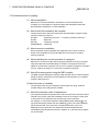
• SAFETY PRECAUTIONS •
(Always read these instructions before using this equipment.)
Before using this product, please read this manual and the relevant manuals introduced in this manual
carefully and pay full attention to safety to handle the product correctly.
The instructions given in this manual are concerned with this product. For the safety instructions of the
programmable controller system, please read the CPU module user's manual.
In this manual, the safety instructions are ranked as "DANGER" and "CAUTION".
DANGER
Indicates that incorrect handling may cause hazardous conditions,
resulting in death or severe injury.
! CAUTION
Indicates that incorrect handling may cause hazardous conditions,
resulting in medium or slight personal injury or physical damage.
!
Note that the ! CAUTION level may lead to a serious consequence according to the circumstances.
Always follow the instructions of both levels because they are important to personal safety.
Please save this manual to make it accessible when required and always forward it to the end user.
[Design Precautions]
!
DANGER
• Make sure to configure the interlock line outside the PLC system so that the system always
operates normally when changing the data and control status of the PLC being operated from a
peripheral device.
Moreover, determine in advance how the system handles with communication errors by poor
cable connection, etc. that may occur when performing online operations on the PLC CPU from
a peripheral device.
!
CAUTION
• Please read this manual thoroughly and confirm the safety before starting online operations
(especially forced outputs and operating status modifications) performed by connecting a
peripheral device to the operating CPU module.
Incorrect online operations may cause damage to the machinery or result in accidents.
A-1
A-1
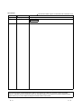
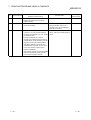
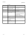
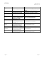
REVISIONS
The manual number is given on the bottom left of the back cover.
Print Date
Apr., 2000
Sep., 2000
Manual Number
SH(NA)-080091-A First printing
SH(NA)-080091-B
Correction
Revision
Section 7.3
Japanese Manual Version SH-080001-A
This manual confers no industrial property rights or any rights of any other kind, nor does it confer any patent
licenses. Mitsubishi Electric Corporation cannot be held responsible for any problems involving industrial property
rights which may occur as a result of using the contents noted in this manual.
2000 MITSUBISHI ELECTRIC CORPORATION
A-2
A-2
INTRODUCTION
Thank you for purchasing the MELSEC-Q/A series PLC.
Before using the equipment, please read this manual carefully to develop full familiarity with the functions
and performance of the Q, A series PLC you have purchased, so as to ensure correct use.
Please forward a copy of this manual to the end user.
CONTENTS
1 OVERVIEW
1- 1 to 1- 2
2 COMMUNICATION MODULE STARTUP AND MODE CHANGE
2- 1 to 2- 5
2.1 Outline of the Startup Procedure ............................................................................................................ 22.1.1 Starting up the QD51 (-R24)............................................................................................................ 22.1.2 Starting up the A1SD51S/AD51H-S3 .............................................................................................. 22.2 About Changing Between the Modes of the Communication Module .................................................. 2-
1
1
2
3
3 COMMAND EXPLANATION FORMAT
3- 1 to 3- 2
4 ONLINE PROGRAMMING OPERATION
4- 1 to 4-41
4.1 System Command List............................................................................................................................ 4- 2
4.2 Operating Procedure for Copying/Deleting the Contents of Memory Cards
For AD51H-S3 Only .......................................................................................................................... 4- 3
4.2.1 Copying the Content of a Memory Card to Another Memory Card Without Change (CCOPY
Command) For AD51H-S3 Only ............................................................................................... 4- 3
4.2.2 Formatting a Memory Card (CFORMAT Command) For AD51H-S3 Only ............................. 4- 5
4.2.3 Displaying Formatting Information of a Memory Card (CFORMAT? Command)
For AD51H-S3 Only ................................................................................................................... 4- 8
4.3 Operating Procedure for Loading/Saving Executable Programs .......................................................... 4-10
4.3.1 Loading Executable Programs to the Communication Module from a Memory Card/EEP-ROM/Flash
ROM (MLOAD Command)............................................................................................................... 4-10
4.3.2 Saving Executable Programs to a Memory Card/EEP-ROM/Flash ROM from the Communication
Module (MSAVE Command) ........................................................................................................... 4-13
4.4 Operating Procedure for Specifying Multitask Settings, Changing Set Data, and Displaying
Set Data................................................................................................................................................... 4-16
4.4.1 Specifying Multitask Settings and Changing Set Data (SET Command)....................................... 4-18
4.4.2 Displaying Set Data for Multitask Settings (SET? Command) ....................................................... 4-21
4.5 Operating Procedure for Changing the Mode of the Communication Module...................................... 4-25
4.5.1 Changing the Mode of the Communication Module to the Edit Mode (1) (START Command) ... 4-25
4.5.2 Changing the Mode of the Communication Module to Execution Mode/System Mode (GO
Command)........................................................................................................................................ 4-29
4.6 Ending the Interpreter Operation in the Specified Task Areas (TKILL Command) .............................. 4-32
A-3
A-3
4.7 Operating Procedure for Displaying the Main Menu Screen on the Console (EXIT Command)........ 4-34
4.8 Operating Procedure for Checking the Input Formats of the System Commands
(HELP Command)................................................................................................................................... 4-36
4.9 Recovering an Area in Unusable File Area in a Memory Card (CRECOVER Command)
For AD51H-S3 Only .......................................................................................................................... 4-38
4.10 Formatting (Logical Format) the File Area of a Memory Card (FFORMAT Command)
For AD51H-S3 Only ....................................................................................................................... 4-40
5 MULTITASK DEBUGGING OPERATIONS
5- 1 to 5-48
5.1 Debug Command List ............................................................................................................................. 5- 2
5.2 Operations for Controlling the Operation of BASIC Programs .............................................................. 5- 3
5.2.1 Displaying the Status of the Specified BASIC Program (TSTATUS Command)........................... 5- 3
5.2.2 Starting the Execution of the Specified BASIC Program (TRUN Command) ................................ 5- 5
5.2.3 Stopping the Execution of the Specified BASIC Program (TSTOP Command) ............................ 5- 7
5.2.4 Resuming the Execution of the Specified BASIC Program Whose Execution Has Been Stopped
(TCONTINUE Command)................................................................................................................ 5-10
5.2.5 Displaying Values of Specified Variables in the Specified BASIC Program (T? Command) ........ 5-12
5.2.6 Assigning Values to Specified Variables in the Specified BASIC Program (TLET command) ..... 5-14
5.3 Internal Memory Read/Write Operations................................................................................................ 5-16
5.3.1 Displaying Values of Buffer Memory/Common Memory/Extension Registers (ED) (MREAD
Command)........................................................................................................................................ 5-17
5.3.2 Writing Values to Buffer Memory/Common Memory/Extension Registers (ED)
(MWRITE Command) ...................................................................................................................... 5-20
5.3.3 Displaying Bit Information of General-Purpose Inputs (X)/General-Purpose Outputs (Y)/Extension
Relays (EM) (B@ Command).......................................................................................................... 5-23
5.3.4 Writing Bit Information to General-Purpose Inputs (X)/Extension Relays (EM) (B@ Command).. 5-26
5.3.5 Displaying Word Information of Extension Registers (ED) (W@ Command) ................................. 5-28
5.3.6 Writing Word Information to Extension Registers (ED) (W@ Command) ...................................... 5-30
5.4 Operations for Checking the Usage of Events/Message Ports/Resource Numbers............................. 5-33
5.4.1 Displaying the Event Enable/Disable Declaration Status (ZSTATUS Command).......................... 5-33
5.4.2 Displaying the Status of Transmission to Message Ports (STATUS Command) ........................... 5-35
5.4.3 Displaying the Reserved/Released Status of Resource Numbers for Exclusive Access Control
(ZSTATUS Command) ..................................................................................................................... 5-37
5.5 Operations for Changing the Mode of the Communication Module....................................................... 5-39
5.5.1 Changing the Communication Mode to Edit Mode (2) (START Command)................................... 5-39
5.5.2 Changing the Mode of the Communication Module to System mode/Execution Mode (2)/Debug
Mode (GO Command) ...................................................................................................................... 5-42
5.6 Operation for Displaying the Main Menu Screen on the Debugger (EXIT Command) ......................... 5-45
5.7 Operation for Checking the Input Formats of the Debug Commands (HELP Command) .................... 5-47
6 CREATING BASIC PROGRAMS WITH A GENERAL-PURPOSE EDITOR
6.1
6.2
6.3
6.4
6.5
6- 1 to 6- 6
Difference between the General-Purpose Editor and Software Package............................................. 6Flow of BASIC Program Creation Using a General-Purpose Editor ..................................................... 6Software Required to Create Programs with a General-Purpose Editor .............................................. 6Precautions when Using a General-Purpose Editor .............................................................................. 6Addition of Line Numbers Using the Line Numbering Tool ................................................................... 6-
A-4
A-4
1
2
2
3
4
6.5.1 Starting up the Line Numbering Tool............................................................................................... 6- 4
6.5.2 Precautions when Using the Line Numbering Tool......................................................................... 6- 6
7 CREATING PROGRAMS USING A COMPILER
7- 1 to 7-23
7.1 Differences between Compiler BASIC and Interpreter BASIC.............................................................. 7- 1
7.2 Flow of Program Creation Using a Compiler ......................................................................................... 7- 2
7.3 Software Required for Compilation ........................................................................................................ 7- 3
7.4 Installing Assembler and Linker.............................................................................................................. 7- 3
7.5 Starting up the Compiler ......................................................................................................................... 7- 4
7.5.1 For IBM PC/AT Compatible PCs ..................................................................................................... 7- 5
7.5.2 For PC-9800 Series ......................................................................................................................... 7- 6
7.6 Precautions when Compiling .................................................................................................................. 7- 7
7.7 How to Run a Program in the Communication Module ......................................................................... 7- 9
7.8 Instruction/Function List .......................................................................................................................... 7-11
7.8.1 List of Whether or not Instructions/Functions can Be Compiled..................................................... 7-11
7.8.2 Instructions/Functions with Different Specifications at Compilation ............................................... 7-16
APPENDIX
App- 1 to App-11
Appendix-1 Error Messages When Using the Line Numbering Tool .......................................................App- 1
Appendix-2 Error Messages at Compilation..............................................................................................App- 2
A-5
A-5
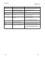
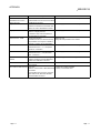
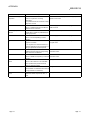
About Manuals
The following manuals are also related to this product.
If necessary, order them by quoting the details in the tables below.
Related Manuals
Manual Name
Manual Number
(Model Code)
Type AD51H-S3 Intelligent Communication Module User's Manual
This manual contains information on the system configuration when using the module, module
specifications, name and setting for each part, description of each function, and external dimensions of
IB-68350
(13JA59)
the module. (Provided with the module)
Type A1SD51S Intelligent Communication Module User's Manual (Hardware)
This manual contains information on the system configuration when using the module, module
specifications, name and setting for each part, and external dimensions of the module. (Provided with the
IB-68487
(13JG56)
module)
Type A1SD51S Intelligent Communication Module User's Manual (Advanced)
This manual contains information on the system configuration when using the module, module
specifications, name and setting for each part, description of each function, and external dimensions of
SH-3523
(13JG57)
the module. (Sold separately)
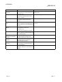
Type QD51/QD51-R24 Q-Corresponding Intelligent Communication Module User's Manual
(Hardware)
This manual contains information on the system configuration when using the module, module
IB-0800130
(13JT05)
specifications, name and setting for each part, and external dimensions of the module. (Provided with the
module)
Type QD51/QD51-R24 Q-Corresponding Intelligent Communication Module User's Manual
(Advanced)
This manual contains information on the system configuration when using the module, module
SH-080092
(13JT06)
specifications, name and setting for each part, description of each function, and external dimensions of
the module. (Sold separately)
AD51H-BASIC Programming Manual (Commands)
This manual contains information on programming methods, commands, and error codes of AD51H-
SH-3525
(13J519)
BASIC. (Sold separately)
Type SW1IVD-AD51HP/SW1NX-AD51HP AD51H-BASIC Package Operating Manual
(Conforming to QD51, QD51-R24, A1SD51S, AD51H-S3)
This manual contains information on how to operate the software packages for IBM PCs/AT compatible
IB-68674
(13J484)
PCs and PC-9800 series. (Provided with the software package)
A-6
A-6
1 OVERVIEW
MELSEC-Q
1 OVERVIEW
1
This programming manual explains system and debug commands as well as
compilation methods used with the communication module.
(1) System and debug commands
The following operations can be performed by entering commands from the
console or debugger:
• Edit and debug a BASIC program.
• Load and save a BASIC program from/to a memory card, floppy disk, or hard
disk.
• Execute, stop, and display the status of a BASIC program.
• Read and write from/to general-purpose input/output and internal devices.
• Change and read multitask settings.
(2) Creation of BASIC programs using a general-purpose editor
It is possible to create BASIC programs in online, using any general-purpose
editor that is available in the market.
Line numbers can furthermore be added to a program created with a generalpurpose editor by using a line numbering tool.
(3) Compiling BASIC programs
It is possible to use a compiler to compile BASIC programs created by interpreter
BASIC.
The execution speed of compiler BASIC is 3 to 4 times faster as compared with
interpreter BASIC.
(4) Making ROM-based BASIC programs for the AD51H-S3
It is possible to store created BASIC programs for the AD51H-S3 in ROM.
1-1
1-1
1 OVERVIEW
MELSEC-Q
MEMO
1
1-2
1-2
2 COMMUNICATION MODULE STARTUP AND MODE CHANGE
MELSEC-Q
2 COMMUNICATION MODULE STARTUP AND MODE CHANGE
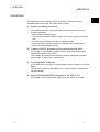
This chapter explains how to start up the communication module and how to change
modes after the startup, when performing the online programming operations
described in Chapter 4 and multitask debugging operations described in Chapter 5.
2
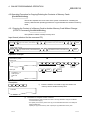
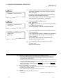
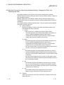
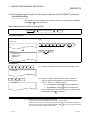
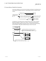
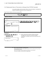
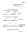
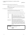
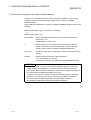
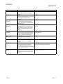
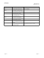
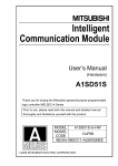
2.1 Outline of the Startup Procedure
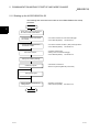
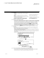
2.1.1 Starting up the QD51 (-R24)
The following flow chart shows an outline of the QD51 (-R24) startup procedure.
Start
Check which functions are going to
be used and their specifications.
Connect the console and module
with a cable.
• Connection between the console and debugger.
• User's Manual (Details) See Section 5.4
Connect the target device and
module with a cable.
• Connection between the QD51 (-R24) and target device
• User's Manual (Details) See Section 5.5
Connect the GPPW and QCPU
with a cable.
Perform various settings via GPPW.
Create the program.
• I/O assignment setting of the QD51 (-R24)
• Mode setting (programming mode) and operation setting of the QD51 (-R24)
• User's Manual (Details) See Section 5.6
• Instructions and functions
• See the Programming Manual (Commands)
Debug the program.
Set the operation mode via GPPW.
• Mode setting (execution mode/debug mode) and operation setting
of the QD51 (-R24)
• User's Manual (Details) See Section 5.6
End
2-1
2-1
2 COMMUNICATION MODULE STARTUP AND MODE CHANGE
MELSEC-Q
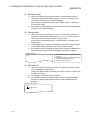
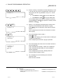
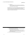
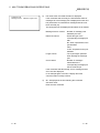
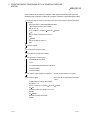
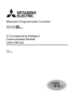
2.1.2 Starting up the A1SD51S/AD51H-S3
The following flow chart shows the outline of the A1SD51S/AD51H-S3 startup
procedure.
Start
2
Check which functions are going to
be used and their specifications.
Connect the console and module
with a cable.
Connect the target device and
module with a cable.
Set various switches.
• Connection between the console and debugger
• User's Manual (Details) See Section 5.4
• Connection between the QD51 (-R24) and target device
• User's Manual (Details) See Section 5.5
• Operation mode setting
• Setting of the console and debugger
• User's Manual (Details) See Section 5.6
Start up the software package.
Create the program.
• Instructions and functions
• See the Programming Manual (Commands)
Debug the program.
Set the operation mode with the
setting switch.
• Operation mode setting
• User's Manual (Details)
See Section 5.6
End
2-2
2-2
2 COMMUNICATION MODULE STARTUP AND MODE CHANGE
MELSEC-Q
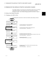
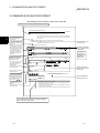
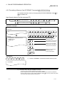
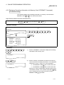
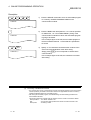
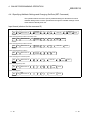
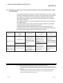
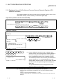
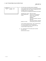
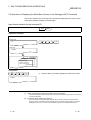
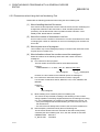
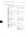
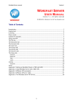
2.2 About Changing Between the Modes of the Communication Module
After starting up the communication module, it is possible to change into various
modes by entering system commands from the console described in Chapter 4 and
debug commands from the debugger described in Chapter 5.
This chapter explains how to change between the modes of the communication
module by entering system commands and debug commands, and provides a brief
description of each mode.
Start up the communication
module.
If the A7PHP/A7HGP/A7LMS is used:
1) Start up the A7PHP/A7HGP/A7LMS with the AD51H-BASIC function.
2) Select Programming in the displayed main menu screen.
3) Select Online programming in the Programming Menu screen displayed.
If mode setting switch 1 of the
communication module is set
to "4":
If mode setting switch 1 of the
communication module is set
to "2"/"3":
If mode setting switch 1 of the
communication module is set
to "0"/"1":
S
Enter
"GO R."
System mode
S
Enter
"START."
B
Enter
"SYSTEM"
or press
Ctrl + D.
Edit
mode (1)
Programming
mode
2-3
Execution
mode
S
Enter
"GO R,
D."
Debug mode
D
Enter
"GO P."
D
Enter
"START."
D
Enter
"GO R."
B
Enter
"SYSTEM"
or press
Ctrl + D .
Edit
mode (2)
S : System command
D : Debug command
B : BASIC command
2-3
2 COMMUNICATION MODULE STARTUP AND MODE CHANGE
MELSEC-Q
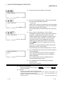
(1) Programming mode
1)
2)
The user can edit, debug, load/save from/to a memory card, and specify
multitask settings for each BASIC program.
There are two modes in programming mode for performing the operations
above: system mode and edit mode (1).
(2) System mode
1)
2)
3)
This is the mode that is changed to when the communication module is
started up by setting mode setting switch 1 to "4" or when the GO command
(GO P) is entered by the debugger in debug mode.
The console is controlled by the operating system (OS) of the
communication module.
It is possible to perform the following operations for each BASIC program, by
entering system commands from the console described in Chapter 4.
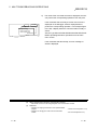
Display on the console
• Load and save BASIC programs from/to a
memory card mounted on MEMORY CARD 1
of the AD51H-S3 and the EEP-ROM's
executable program area of the A1SD51S.
• Specify multitask settings, etc.
S>
(3) Edit mode (1)
1)
2)
3)
This is the mode that is changed to when the START command is entered
on the console in system mode.
The console input is used by the interpreter (an OS that analyzes and
executes BASIC commands).
It is possible to perform the following operations for each BASIC program, by
entering instructions/functions of AD51H-BASIC from the console.
Display on the console
OK
Cursor position
2-4
• Editing and debugging
• Load and save BASIC programs from/to the
memory card file area.
2-4
2 COMMUNICATION MODULE STARTUP AND MODE CHANGE
MELSEC-Q
(4) Execution mode
1)
2)
This is the mode that is changed to when the communication module is
started up by setting mode setting switch 1 to "0" or "1" or when the GO
command is entered from the console/debugger.
(If the RUN key switch/RUN switch is in the "RUN" position, it changes to
the execution mode.)
It is possible to fundamentally control the system by running multiple BASIC
programs in the multitask settings.
(5) Debug mode
1)
2)
3)
This is the mode that is changed to when the communication module is
started up by setting mode setting switch 1 to "2" or "3," or when the GO
command is entered from the console in system mode.
(If the RUN key switch/RUN switch is in "RUN" position, it changes to the
debug mode.)
The debugger input is used by the debugger function (an OS that analyzes
and executes debug commands) of the communication module.
It is possible to debug each BASIC program while executing multitasking by
entering debug commands from the debugger described in Chapter 5.
Debugger terminal
• Control the execution of the specified BASIC
programs.
• Input/output data to/from memory and devices
accessible from BASIC programs.
• Change to other modes, etc.
D>
(6) Edit mode (2)
1)
2)
3)
This is the mode that is changed to when the START command is entered
from the debugger in debug mode.
(Tasks other than the task specified by the START command continue their
multitask processing.)
The debugger is controlled by the interpreter.
It is possible to modify any BASIC program while executing other BASIC
programs by entering instructions/functions of AD51H-BASIC from the
debugger.
Display on the console
OK
Cursor position
2-5
2-5
3 COMMAND EXPLANATION FORMAT
MELSEC-Q
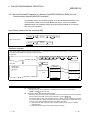
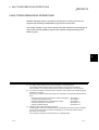
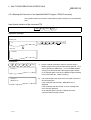
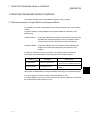
3 COMMAND EXPLANATION FORMAT
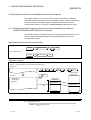
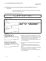
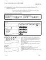
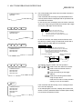
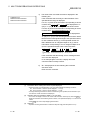
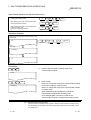
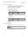
The following format is used to explain each command.
The title of each command classification is listed here.
4 ONLINE PROGRAMMING OPERATION
MELSEC-A
4.2 Operating Procedure for Copying/Deleting the Contents of Memory Cards
3
This section explains how to use each of the system commands for controlling the
memory cards and the operating procedure to copy and delete the contents of
memory cards.
The operating content when
the command is used is
described here.
"Input format" describes the
sequence of commands and
parameters.
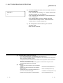
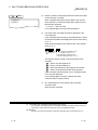
This indicates a short-cut key
when entering the command
from the keyboard. In this case,
if the abbreviation key input
CC is entered, the same
processing as if the CCOPY
command were called will
take place.
In the operation example, an
Rexample
}
hof the
g pkey input
e and
L the screens
B
procedure
displayed is shown when
using the command.
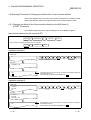
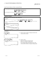
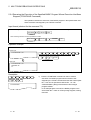
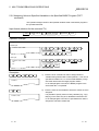
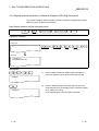
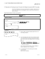
4.2.1 Copying the Content of a Memory Card to Another Memory Card Without Change
(CCOPY Command)
Input format (shortcut for the command CC)
When checking that contents of the copy source and destination match after copying.
COOPY
SP
Copy source memory card interface No.
:
,
Copy destination memory card interface No.
"Description" describes the
input procedure and input
method of the commands
and parameters shown in
the operation example in
the order from 1 to n .
This shows the key input
sequence.
This is an image of the screen
after the key input.
,
V
Enter
Matching
When simply copying
COOPY
SP
,
:
Copy source memory card interface No.
:
Copy destination memory card interface No.
Enter
Command
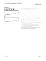
Operation example
Copy the contents of a memory card mounted in MEMORY CARD 1 to a memory card mounted in MEMORY CARD 2 and check
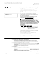
Operation performed
by the command and
a description.
The key input
sequence for
performing the
operation is
shown here.
Before input
S>
C
After input
O
C
,
V
Matching
S>COOPY 0:,1:,V
COPY(Y/N)?Y
COPY OK
S>
This is an image of the screen
before the key input.
This is an image of the screen
after the key input.
:
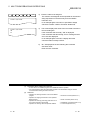
Command
P
Y
SP
Command
The operating content when
using the command is
described here.
The command name
is shown here.
This operation creates a backup memory card.
Enter
0
Copy source
memory card
interface No.
V
:
,
1
:
Copy destination
memory card
interface No.
Enter
Specifying copy
The key input when
using the command is
shown here.
Description
C
C
O
P
Y
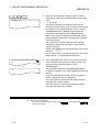
1)
Enter the CCOPY command to copy the contents of a
memory card to another memory card.
S>COOPY
This is a description
about the key input.
(1)
Precautions on using the CCOPY command
• Format the memory card mounted in the drive on the copy destination using the
CFORMAT command before copying.
• The capacity of the memory cards in the copy source and destination drives must
satisfy the following relationship.
Capacity of copy source memory card <
= Capacity of copy destination memory card
4-3
This is a description of items that the user should know
when using the command and commands related to
the command being explained.
3-1
3-1
3 COMMAND EXPLANATION FORMAT
MELSEC-Q
MEMO
3
3-2
3-2
4 ONLINE PROGRAMMING OPERATION
MELSEC-Q
4 ONLINE PROGRAMMING OPERATION
Online programming refers to editing and debugging BASIC programs, as well as
loading and saving BASIC programs from/to memory cards, user-made floppy disks,
and hard disks using the console connected to the communication module.
(Only one BASIC program in one task can be debugged at a time in online
programming.)
This chapter explains how to use system commands for editing and debugging BASIC
programs, as well as loading and saving BASIC programs from/to memory cards, usermade floppy disks, and hard disks using the console in system mode.
4
(1)
(2)
4-1
This chapter mainly explains the key inputs and displays on the console side.
It is therefore generally omitted to state this fact explicitly for most key inputs and displays.
When necessary, it is pointed out explicitly that key inputs and displays are on the debugger side.
It is necessary to perform the following tasks in advance in order to perform the online programming
described in this chapter.
Perform each operation beforehand according to the explanation in the reference chapters below.
• In order to establish communication for performing online programming, the user should:
Set the switches of the module : See Chapter 2.
• Connect the console
: See Chapter 2.
4-1
4 ONLINE PROGRAMMING OPERATION
MELSEC-Q
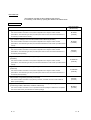
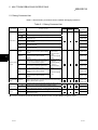
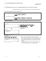
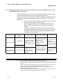
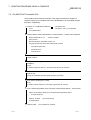
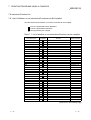
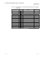
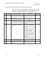
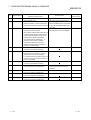
4.1 System Command List
Table 4.1 lists system commands entered on the console from the keyboard during
online programming.
Table 4.1 System Command List
Classification
Memory card
control
System
command
Availability for module
Function overview
AD51H-S3 A1SD51S
QD51
(-R24)
CCOPY
Copies the contents of a memory card to another memory
card without change. (Creation of a memory card for
backup)
Section
4.2.1
CFORMAT
Formats (physical format) a memory card.
Section
4.2.2
CFORMAT? Displays formatting information of a memory card.
Recovers a file area in the unusable status to the usable
CRECOVER
status.
Multitask
setting control
Loads the contents of the specified BASIC task area in a
memory card/EEP-ROM to the target BASIC task area of
the communication module.
Section
4.3.1
MSAVE
Saves the contents of the specified BASIC task area of the
communication module to the target BASIC task area of a
memory card/EEP-ROM. (The multitask settings are
automatically specified)
Section
4.3.2
SET
Changes the multitask settings.
Section
4.4.1
SET?
Displays the specified data of the multitask settings.
Section
4.4.2
Changes the mode of the communication module from
system mode to edit mode (1). (For editing and debugging
each program)
Section
4.5.1
Changes the mode of the communication module from
system mode to execution mode (2) or debug mode.
Section
4.5.2
1
MLOAD
1
Mode control
GO
Others
Section 4.9
Section
4.10
START
Interpreter
operation
control
Section
4.2.3
Formats (logical format) the file area of a memory card.
FFORMAT
Executable
program
information
control
Reference
section
Ends the operation of the interpreter in the specified
BASIC task area of the communication module.
Section 4.6
EXIT
Displays the main menu screen on the console.
Section 4.7
HELP
Displays the system command list, function overview, and
command input format.
Section 4.8
TKILL
1
1 These commands cannot be executed on tasks in which compiled BASIC programs are stored.
4-2
4-2
4
4 ONLINE PROGRAMMING OPERATION
MELSEC-Q
4.2 Operating Procedure for Copying/Deleting the Contents of Memory Cards
For AD51H-S3 Only
This section explains how to use each of the system commands for controlling the
memory cards and the operating procedure to copy and delete the contents of memory
cards.
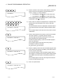
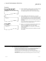
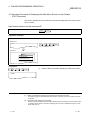
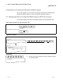
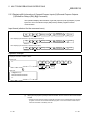
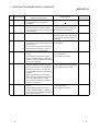
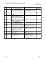
4.2.1 Copying the Content of a Memory Card to Another Memory Card Without Change
(CCOPY Command) For AD51H-S3 Only
This operation creates a backup memory card.
Input format (shortcut for the command CC)
When checking that the contents of the copy source and destination match after copying.
CCOPY
SP
Copy source memory card interface No.
:
,
:
Copy destination memory card interface No.
,
V
Enter
Matching
Command
When simply copying
CCOPY
SP
:
Copy source memory card interface No.
,
:
Copy destination memory card interface No.
Enter
Command
Operation example
Copy the contents of the memory card mounted in MEMORY CARD 1 to the memory card mounted in MEMORY CARD 2 and
check that they match.
Before input
S>
C
C
O
P
Y
SP
Command
,
After input
V
Matching
S>CCOPY 0:,1:,V
COPY(Y/N)?Y
COPY OK
S>
0
Copy source
memory card
interface No.
Enter
V
:
,
1
:
Copy destination
memory card
interface No.
Enter
Specifying copy
Description
C
C
O
P
Y
1)
Enter the CCOPY command to copy the content of a
memory card to another memory card.
S>CCOPY
(1)
Precautions on using the CCOPY command
• Format the memory card mounted in the drive on the copy destination using the CFORMAT
command before copying.
• The capacity of the memory cards in the copy source and destination drives must satisfy the
following relationship.
Capacity of copy source memory card ≤ Capacity of copy destination memory card
4-3
4-3
4 ONLINE PROGRAMMING OPERATION
SP
0
:
,
1
:
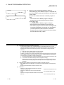
2)
S>CCOPY 0:,1:
MELSEC-Q
Enter the memory card interface number followed by a colon
(:) for both the copy source and destination. Enter the copy
source first, then the copy destination. Only 0 or 1 can be
specified.
0 : The MEMORY CARD 1 drive on the AD51H-S3.
1 : The MEMORY CARD 2 drive on the AD51H-S3.
In the example figure to the left, the contents of a memory
card in MEMORY CARD 1 are copied to a memory card in
MEMORY CARD 2 .
,
V
Enter
3)
Specify "V" if it should be checked that the contents of the
copy source and destination match after the copying.
Press Enter if it is not required to check that the contents
match.
In the example figure to the left, the contents are checked
after copying.
4)
The screen displays "COPY (Y/N)? "
Enter Y to copy.
Enter N to stop copying. (The console returns to waiting for
a system command entry.)
In the example figure to the left, copying is specified.
5)
The screen displays the result of the command execution in
the succeeding line.
If the command ends normally, "COPY OK" is displayed.
If the command ends abnormally, an error message or
similar is displayed.
In the example figure to the left, a display where the
command ends normally is shown.
6)
"S>" is displayed in the line following the command
execution result.
Enter the next command.
S>CCOPY 0:,1:,V
Y
Enter
S>CCOPY 0:,1:,V
COPY(Y/N)?Y
S>CCOPY 0:,1:,V
COPY(Y/N)?Y
COPY OK
S>
(2)
Reference
• Operation for formatting a memory card
• Operation for displaying formatting information of a
memory card
4-4
: CFORMAT command (Section 4.2.2)
: CFORMAT? command (Section 4.2.3)
4-4
4 ONLINE PROGRAMMING OPERATION
MELSEC-Q
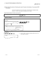
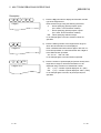
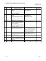
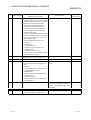
4.2.2 Formatting a Memory Card (CFORMAT Command) For AD51H-S3 Only
This operation formats a memory card (physically) mounted in MEMORY CARD 1 or
2 on the AD51H-S3.
Input format (shortcut for the command CF)
CFORMAT
SP
Memory card interface No.
:
,
"
,
0
,
Card name
"
,
Overall size
Command
,
Size of executable program area
File area size
Enter
Operation example
Format the memory card (with a capacity of 512 K bytes) mounted in MEMORY CARD 1 under the following conditions.
Before input
S>
C
F
O
R
M
A
T
SP
Command
"
After input
T
A
S
0
:
,
"
,
Memory card
interface No.
K
-
D
T
M
Card name
S>CFORMAT 0:,"TASK-DTM",8,6,0,2
FORMAT(Y/N)?Y
FORMAT OK
S>
Name to be assigned to
the memory card
8
,
Total capacity of the memory
card (8 units of 64 K bytes)
,
Capacity of the executable
program area in the memory
card (8 units of 64 K bytes)
Overall size
6
Size of executable program area
0
,
2
Enter
File area size
Y
Capacity of the file area in
the memory card
(2 units of 64 K bytes)
Enter
Format specification
Description
C
F
O
R
M
A
T
1)
Enter the CFORMAT command to format a memory card.
S>CFORMAT
(1)
Precautions when using the CFORMAT command
• If a memory card is formatted, all data that was written is deleted.
• When formatting a memory card that is write protected, the write protect should be canceled first.
• When formatting a memory card mounted in MEMORY CARD 1 , the memory protection key switch
of the AD51H-S3 module should be turned off first.
4-5
4-5
4 ONLINE PROGRAMMING OPERATION
SP
0
:
2)
,
S>CFORMAT 0:,
MELSEC-Q
Enter the number of the memory card interface in which the
memory card to be formatted is mounted followed by a
colon (:). Only 0 or 1 can be specified.
0 : The MEMORY CARD 1 drive on the AD51H-S3.
1 : The MEMORY CARD 2 drive on the AD51H-S3.
In the example figure to the left, the memory card mounted
in MEMORY CARD 1 is specified.
"
T
A
S
K
D
T
M
"
,
-
3)
Enter a name of maximum 16 alphanumeric characters and
symbols that will be assigned to the memory card after
formatting.
The first character must be an alphabetic character and the
name area should be enclosed by double quotation marks
(").
In the example figure to the left, the memory card is named
TASK-DTM.
4)
Enter the total capacity of the memory card to be formatted.
This value must be 1 or greater (unit: 64 K bytes).
The total capacity must be the total value of each of the
sizes specified in the following formula.
Overall size (total capacity) = (size of executable program
area + file area size)
In the example figure to the left, the memory card is
formatted to contain 512 K bytes.
(8 64 K bytes 512 K bytes)
5)
Enter the capacity reserved for the executable program area
in the memory card after the formatting. This value must be
from 0 to 6 (unit: 65 K bytes).
The maximum capacity of the executable program area is
384 K bytes. It is used for the OS area (128 K bytes) and all
of the BASIC task areas (where executable programs are
stored).
In the example figure to the left, 384 K bytes are reserved
for the executable program area.
6)
Enter 0 as a placeholder.
S>CFORMAT 0:,"TASK-DTM",
8
,
S>CFORMAT 0:,"TASK-DTM",8,
6
,
S>CFORMAT 0:,"TASK-DTM",8,6,
0
,
S>CFORMAT 0:,"TASK-DTM",8,6,0,
4-6
4-6
4 ONLINE PROGRAMMING OPERATION
2
Enter
7)
Enter the capacity reserved for the file area in the memory
card after the formatting. This value must be 0 or greater
(unit: 64 K bytes).
This area is used to store BASIC programs and data files
that are not stored in the BASIC task areas.
In the example figure to the left, 128 K bytes are reserved
for the file area. (2 64 K bytes 128 K bytes)
8)
The screen displays "FORMAT (Y/N)? "
Enter Y to format.
Enter N to stop formatting. (The console returns to waiting
for a system command entry.)
In the example figure to the left, formatting is specified.
9)
The screen displays the result of the command execution in
the succeeding line.
If the command ends normally, "FORAMT OK" is displayed.
If the command ends abnormally, an error message or
similar is displayed.
In the example figure to the left, a display where the
command ends normally is shown.
S>CFORMAT 0:,"TASK-DTM",8,6,0,2
Y
Enter
S>CFORMAT 0:,"TASK-DTM",8,6,0,2
FORMAT(Y/N)?Y
S>CFORMAT 0:,"TASK-DTM",8,6,0,2
FORMAT(Y/N)?Y
FORMAT OK
S>
MELSEC-Q
10) "S>" is displayed in the line following the command
execution result.
Enter the next command.
(2)
Precautions on specifying each of the sizes in the CFORMAT command
• The overall size (total capacity) should be specified so that it matches with the capacity of the
memory card to be formatted. Moreover, it must be equal to the total value of the sizes of the
executable program area and file area.
• If all the remaining area, excluding the OS area, in the executable program area of the memory card
is divided into eight BASIC task areas and each area has the same capacity, the maximum capacity
of one area is approximately 48 K bytes.
• Sizes can be specified in hexadecimal digits ("&H
") or binary digits ("&B
to
"),
instead of decimal digits.
(3)
About logical formatting of a memory card
• When the SET or MSAVE commands are executed for the first time, the executable program area of
the memory card is logically formatted.
• Use the FFORMAT command for logical formatting of the file area.
(4)
Reference
• Operation for displaying formatting information of a
memory card
4-7
: CFORMAT? command (Section 4.2.3)
4-7
4 ONLINE PROGRAMMING OPERATION
MELSEC-Q
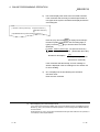
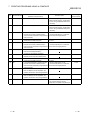
4.2.3 Displaying Formatting Information of a Memory Card (CFORMAT? Command)
For AD51H-S3 Only
This operation displays the formatting information of a memory card mounted in
MEMORY CARD 1 or 2 on the AD51H-S3 module.
Input format (shortcut for the command CF?)
CFORMAT?
SP
:
Memory card interface No.
Enter
Command
Operation example
Display the formatting information of a memory card mounted in MEMORY CARD 1 of the module.
Before input
S>
C
F
O
R
M
A
T
?
SP
Command
Enter
0
After input
Memory card
interface No.
S>CFORMAT? 0:
Card Name : "TASK-DTM"
: 512K bytes (8)
Card Size
Program Size : 384K bytes (6)
Canvas Size : 0K bytes (0)
: 128K bytes (2)
File Size
Description
C
F
?
SP
O
R
M
A
T
1)
Enter the CFORMAT? command to display the formatting
information of the memory card.
2)
Enter the memory card interface number for the memory
card for which the formatting information is to be displayed
followed by a colon (:). Only 0 or 1 can be specified.
0 : The MEMORY CARD 1 drive on the AD51H-S3.
S>CFORMAT?
0
:
Enter
S>CFORMAT? 0:
1 : The MEMORY CARD 2 drive on the AD51H-S3.
Note that "0" may be omitted when specifying the memory
card interface number. If it is omitted, simply press Enter .
In the example figure to the left, the memory card in
MEMORY CARD 1 is specified.
4-8
4-8
4 ONLINE PROGRAMMING OPERATION
3)
S>CFORMAT 0:
Card Name : "TASK-DTM"
Card Size
: 512K bytes (8)
Program Size : 384K bytes (6)
Canvas Size : 0K bytes (0)
File Size
: 128K bytes (2)
MELSEC-Q
The screen displays the result of the command execution.
If the command ends normally, the formatting information of
the specified memory card is displayed from the next line.
If the command ends abnormally, an error message or
similar is displayed.
The following information is displayed when the command
ends normally (see the figure to the left).
• Card Name
: Memory card name assigned during
formatting
• Card Size
: The capacity corresponding to the value
specified as the overall size during
formatting (total capacity of the memory
card)
This is the value specified as the overall
size during formatting.
• Program Size : The capacity corresponding to the value
specified as the executable program area
size during formatting (the capacity of the
executable program area)
The value in parentheses is the value
specified for the executable program
area size when the CFORMAT command
was used to format the memory card.
• Canvas Size : Please ignore.
• File Size
: The capacity corresponding to the value
specified for the file area size during
formatting (the capacity of the file area)
The value in parentheses is the value
specified for the file area size when the
CFORMAT command was used to format
the memory card.
4)
(1)
"S>" is displayed on the line following the command
execution result.
Enter the next command.
Reference
• Operation for formatting a memory card
4-9
: CFORMAT command (Section 4.2.2)
4-9
4 ONLINE PROGRAMMING OPERATION
MELSEC-Q
4.3 Operating Procedure for Loading/Saving Executable Programs
This chapter explains how to use each of the system commands for controlling
executable program information and the operating procedure. These commands can
be used to load an executable program in a BASIC task number area of the
communication module to a memory card/EEP-ROM/flash ROM, and vice versa.
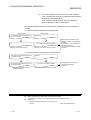
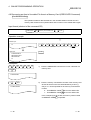
4.3.1 Loading Executable Programs to the Communication Module from a Memory
Card/EEP-ROM/Flash ROM (MLOAD Command)
This operation loads an executable program from the specified BASIC task area in a
memory card/EEP-ROM/flash ROM to the specified BASIC task area of the
communication module.
Input format (shortcut for the command ML)
When checking that the contents of the load source and destination match after loading
MLOAD
SP
V
,
BASIC task No.
Command
Enter
Matching
When simply loading
MLOAD
SP
BASIC task No.
Enter
Command
Operation example
Load the executable program in the area of BASIC task No. 1 of the memory cards executable program area into the area of BASIC
task No. 1 of the AD51H-S3 and check that their contents match.
Before input
S>
M
L
O
A
D
SP
BASIC task
No.
Command
Y
After input
Enter
Specify
loading
S>MLOAD 1,V
LOAD(Y/N)?Y
LOAD OK
S>
1
Memory card
OS area
Area of
BASIC task No. 1
Executable program
area
,
V
Enter
Matching
Program area of
AD51H-S3
Area of
BASIC task No. 1
File area
(1)
Target memory card
• The target memory card of the MLOAD command should be the memory card mounted in
MEMORY CARD 1 of the AD51H-S3.
4 - 10
4 - 10
4 ONLINE PROGRAMMING OPERATION
MELSEC-Q
Description
M
L
O
A
D
SP
1)
Enter the MLOAD command to load an executable program
from a memory card/EEP-ROM/flash ROM into the
executable program area of the communication module.
2)
Enter the BASIC task number (task No. 1 to 8 can be
specified for AD51H-S3, 1 or 2 for A1SD51S/QD51 (-R24))
of the executable program area of the memory card/EEPROM/flash ROM from which the executable program should
be loaded.
In the example figure to the left, the executable program is
loaded from the area of BASIC task No. 1.
3)
Specify "V" if it should be checked that the contents of the
load source and destination match after loading.
Simply press Enter if it is not required to check that the
contents match.
In the example figure to the left, the contents are checked
after loading.
S>MLOAD
1
S>MLOAD 1
,
V
O
Enter
S>MLOAD 1,V
(2)
Precautions when using the MLOAD command
• The size of the specified BASIC task area of the memory card/EEP-ROM/flash ROM (specified by
the MSAVE or SET command) and the size of the corresponding BASIC task area of the
communication module (specified by the START command) must be the same.
• Specify the interpreter in such a way that it does not run in the BASIC task area of the
communication module to which the executable program of the memory/EEP-ROM/flash ROM is
going to be saved.
The operation of the interpreter should be terminated using the TKILL command if it is running.
4 - 11
4 - 11
4 ONLINE PROGRAMMING OPERATION
Y
Enter
4)
The screen displays "LOAD (Y/N)? "
Enter Y to load.
Enter N to stop loading. (The console returns to waiting for
a system command entry.)
In the example figure to the left, loading is specified.
5)
The screen displays the result of the command execution in
the succeeding line.
If the command ends normally, "LOAD OK" is displayed.
If the command ends abnormally, an error message or
similar is displayed.
In the example figure to the left, a display where the
command ends normally is shown.
6)
"S>" is displayed in the line following the command
execution result.
Enter the next command.
S>MLOAD 1,V
LOAD(Y/N)?Y
S>MLOAD 1,V
LOAD(Y/N)?Y
LOAD OK
S>
(3)
Reference
• Operation for saving executable programs of the
communication module to a memory card/EEP-ROM/flash
ROM
• Operation for specifying multitask settings and changing
already set data
• Operation for displaying specified data of multitask settings
• Operation for changing the mode of the communication
module to the edit mode (1)
• Operation for ending the operation of the interpreter in the
specified BASIC task area
4 - 12
MELSEC-Q
: MSAVE command (Section 4.3.2)
: SET command (Section 4.4.1)
: SET? command (Section 4.4.2)
: START command (Section 4.5.1)
: TKILL command (Section 4.6)
4 - 12
4 ONLINE PROGRAMMING OPERATION
MELSEC-Q
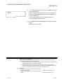
4.3.2 Saving Executable Programs to a Memory Card/EEP-ROM/Flash ROM from the
Communication Module (MSAVE Command)
This operation saves an executable program in the specified BASIC task area of the
communication module onto the target BASIC task area in a memory card/EEPROM/flash ROM. The multitask settings are automatically specified for the relevant
task area by this operation.
Input format (shortcut for the command MS)
When checking that the contents of the save source and destination match after saving
MSAVE
SP
V
,
Task No.
Command
Enter
Matching
When simply saving
MSAVE
SP
Enter
Task No.
Command
Operation example
Save an executable program in the area of BASIC task No. 1 of the AD51H-S3 to the area of BASIC task No. 1 of the memory cards
executable program area and check that the contents match.
Before input
S>
M
S
A
V
E
SP
1
Task No.
Command
,
Enter
V
Matching
Main memory
Y
After input
Enter
Specify
loading
S>MSAVE 1,V
SAVE(Y/N)?Y
SAVE OK
S>
Memory card
OS area
Area of
BASIC task No. 1
Executable program
area
Area of
BASIC task No. 1
File area
(1)
Target memory card
• The target memory card of the MSAVE command should be the memory card mounted in
MEMORY CARD 1 of the AD51H-S3.
(2)
Precautions when using the MSAVE command
• Start up the interpreter with the START command, then execute the MSAVE command immediately
after executing the SYSTEM command to the interpreter or pressing Ctrl + D .
• The following tasks should be performed again if the save capacity (the size specified by the START
command) exceeds the capacity of the BASIC task area when saving again to a BASIC task area of
a memory card to which executable programs have already been saved:
1) Save all the executable programs to the executable program area of a memory card/EEPROM/flash ROM.
2) Modify the setting contents of the multitask settings accordingly.
4 - 13
4 - 13
4 ONLINE PROGRAMMING OPERATION
MELSEC-Q
Description
M
S
A
V
E
SP
1)
Enter the MSAVE command to save an executable program
to a memory card/EEP-ROM/flash ROM from the
communication module.
2)
Enter the BASIC task area (task No. 1 to 8 can be specified
for AD51H-S3, 1 or 2 for A1SD51S/QD51 (-R24)) of the
communication module from which the executable program
is going to be saved.
In the example figure to the left, the executable program in
the area of BASIC task No. 1 of the AD51H is specified to
be saved.
3)
Specify "V" if it should be checked that the contents of the
save source and destination match after saving.
Simply press Enter if it is not required to check that the
contents match.
In the example figure to the left, the contents are checked
after saving.
S>MSAVE
1
S>MSAVE 1
,
V
O
Enter
S>MSAVE 1,V
(3)
Processing of the MSAVE command
• The contents of the memory corresponding to the size of the BASIC task area of the communication
module specified by the START command are saved in the target BASIC task area of a memory
card/EEP-ROM/flash ROM as an executable program.
• After saving the executable program, the multitask settings are automatically specified for the
relevant BASIC task area.
The following settings are specified. See the reference section in the SET command for details.
Startup condition : The "BOOT" attribute is set.
Size
: The task size value specified at the START command execution is set.
Startup order
: No setting is made.
4 - 14
4 - 14
4 ONLINE PROGRAMMING OPERATION
Y
Enter
4)
The screen displays "SAVE (Y/N)?"
Enter Y to save.
Enter N to stop saving. (The console returns to waiting for
a system command entry.)
In the example figure to the left, the save is specified.
5)
The screen displays the result of the command execution in
the succeeding line.
If the command ends normally, "SAVE OK" is displayed.
If the command ends abnormally, an error message or
similar is displayed.
In the example figure to the left, a display where the
command ends normally is shown.
6)
"S>" is displayed in the line following the command
execution result.
Enter the next command.
S>MSAVE 1,V
SAVE(Y/N)?Y
S>MSAVE 1,V
SAVE(Y/N)?Y
SAVE OK
S>
(4)
Reference
• Operation for saving executable programs from a memory
card/EEP-ROM/flash ROM to the main memory
• Operation for specifying multitask settings and changing the
setting contents
• Operation for displaying the setting contents of the multitask
settings
• Operation for changing the mode of the communication
module to the edit mode (1)
4 - 15
MELSEC-Q
: MLOAD command (Section 4.3.1)
: SET command (Section 4.4.1)
: SET? Command (Section 4.4.2)
: START command (Section 4.5.1)
4 - 15
4 ONLINE PROGRAMMING OPERATION
MELSEC-Q
4.4 Operating Procedure for Specifying Multitask Settings, Changing Set Data, and
Displaying Set Data
This chapter explains how to use each of the system commands for controlling
multitask settings and the operating procedure to specify multitask settings, modify set
data, and display set data.
Multitask settings refer to the startup condition settings used when starting up the
communication module in execution mode and executing multiple BASIC programs in
multitasking.
The multitask settings include the following items. They are specified with the MSAVE
command or the SET command.
(a) Startup conditions
Specifies the startup conditions under which the BASIC program in the
target BASIC task area is executed.
1) START
• After powering on or resetting the communication module,
executable programs in the specified target BASIC task areas of a
memory card/EEP-ROM/flash ROM are loaded into the
corresponding executable program areas of the communication
module, after which the programs are executed.
(b)
4 - 16
2)
BOOT
• Executable programs in the specified target BASIC task areas of a
memory card/EEP-ROM/flash ROM are loaded into the
corresponding executable program areas of the communication
module when the communication module is started up.
• They are executed when a currently running BASIC program directs
an order to execute by the ZSTART instruction.
3)
IT
• Executable programs in the target BASIC task areas of a memory
card/EEP-ROM/flash ROM are loaded into the executable program
area of the communication module when the communication module
is started up.
• They are executed when the PLC CPU turns on the specific output
(the startup task number specification flag and task startup signal) of
the communication module.
4)
ON
• The specified programs are loaded from the file area of a memory
area, etc. and executed when a currently running BASIC program
directs an order by the ZSTART instruction after the communication
module has been started up.
5)
OFF
• The multitask settings of the target task area are canceled.
BASIC programs cannot be run in the target task areas.
Task size
Set the size (16 K bytes, 32 K bytes, 48 K bytes, 64 K bytes) of the target
BASIC task area.
4 - 16
4 ONLINE PROGRAMMING OPERATION
(c)
MELSEC-Q
Startup order
Specify which program should be executed first when multiple BASIC
programs are loaded into the corresponding task areas and executed when
the communication module is started up.
If executable programs are saved into the executable program area (used as multiple
BASIC task areas) of a memory card/EEP-ROM/flash ROM using the MSAVE
command, the multitask settings are specified automatically for the target BASIC task
areas. This section explains the available operations for the aforementioned multitask
settings, and for changing and verifying set data.
(1)
About changing the task size of the multitask setting
• The following tasks should be performed again if the size of the multitask setting is changed so that
the size of the target task area exceeds the current size.
1) Save all the executable programs in the communication module with the SAVE instruction.
2) Change the set data in the multitask setting accordingly.
(Specify each task size in such a way that all the executable programs can be saved within the
executable program area size specified when the target memory card was formatted.)
3) Reset the communication module.
4) Load the executable programs with the LOAD instruction and execute the MSAVE command.
(2)
4 - 17
See Section 4.3.2 for more information about the MSAVE command.
4 - 17
4 ONLINE PROGRAMMING OPERATION
MELSEC-Q
4.4.1 Specifying Multitask Settings and Changing Set Data (SET Command)
This operation allows the user to specify multitask settings for task areas for which
multitask settings have not been specified and change the multitask settings of task
areas that have already been set.
Input format (shortcut for the command S)
When setting/changing startup conditions, size, and startup order
SET
SP
BASIC task No.
,
Startup
condition
,
I
P
,
,
Task size
Startup
order
Enter
Command
When changing startup condition and startup order
SET
SP
BASIC task No.
Startup
order
,
Startup
condition
,
I
P
,
,
Startup
condition
,
I
P
,
,
Startup
condition
,
I
P
Enter
Enter
Command
When changing startup condition and size
SET
SP
BASIC task No.
Task size
Enter
Command
When changing startup condition
SET
SP
BASIC task No.
Command
When changing size and startup order
SET
SP
,
,
I
P
,
Task size
BASIC task No.
,
,
I
P
,
,
BASIC task No.
,
,
I
P
,
BASIC task No.
,
Startup
order
Enter
Command
When changing startup order
SET
SP
Startup
order
Enter
Command
When changing size
SET
SP
Task size
Enter
Command
4 - 18
4 - 18
4 ONLINE PROGRAMMING OPERATION
MELSEC-Q
Operation example
Specify the multitask settings for BASIC task No. 1 area
Before input
S>
S
E
T
SP
1
Task No.
Command
,
S
T
A
R
T
Startup condition
After input
S>SET 1,START,IP,48,2
SET OK
S>
,
I
P
,
4
8
Task size
,
2
Enter
Startup order
Description
S
E
T
SP
1)
Enter the SET command for specifying the multitask settings
or changing the set data.
2)
Enter the BASIC task area (task No. 1 to 8 can be specified
for AD51H-S3, 1 or 2 for A1SD51S/QD51 (-R24)) for which
the settings should be specified/changed.
In the example figure to the left, the multitask settings/ set
data of BASIC task No. 1 area of the communication
module will be specified/changed.
3)
Enter one of the following attributes in order to
specify/change the startup condition under which a BASIC
program is executed in the target BASIC task area.
• START
• BOOT
• IT
• ON
• OFF
Simply enter a comma (,) if a startup condition is not to be
specified.
In this case, it is assumed that the startup condition that has
already been set will not be changed.
In the example figure to the left, the START attribute is set
as the startup condition.
S>SET
1
S>SET 1
,
S
T
A
R
S>SET 1,START
(1)
4 - 19
T
See Section 4.4 for more information on the options for the startup condition.
4 - 19
4 ONLINE PROGRAMMING OPERATION
,
I
P
MELSEC-Q
4)
Enter IP as the type of program to be executed.
5)
Enter one of the following values in order to set/change the
task size of the target BASIC task area.
16, 32, 8, 64
Simply enter a comma (,) if a task size is not to be specified.
In this case, it is assumed that the current size of the target
BASIC task area will not be changed.
In the example figure to the left, the task size is set to 48 K
bytes.
6)
Enter a number in the range from 1 to 8 in order to
set/change the execution order (execution startup order) of
programs in multiple BASIC task areas for which the
"START" attribute is set as the startup condition when the
communication module is initiated (1 is the top priority).
If the same number is set for multiple task areas, the
program with the smaller task number is executed first.
Simply Enter a comma (,) if a startup order is not to be
specified.
In this case, it is assumed that the startup order that has
already been set will not be changed.
In the example figure to the left, a startup order of 2 is set.
7)
The screen displays the result of the command execution in
the succeeding line.
If the command ends normally, "SET OK" is displayed.
If the command ends abnormally, an error message or
similar is displayed.
In the example figure to the left, a display where the
command ends normally is shown.
8)
"S>" is displayed in the line following the command
execution result.
Enter the next command.
S>SET 1,START,IP
,
4
8
S>SET 1,START,IP,48
,
2
O
Enter
S>SET 1,START,IP,48,2
S>SET 1,START,IP,48,2
SET OK
S>
(2)
About the size specification
• Sizes can be specified in hexadecimal digits ("&H
instead of decimal digits.
(3)
") or binary digits ("&B
"),
Reference
• Operation for saving BASIC task area information of the
communication module to a memory card/EEP-ROM/flash ROM
• Operation for displaying the multitask settings
• Operation for changing the mode of the communication module
to the edit mode (1)
4 - 20
to
: MSAVE command (Section 4.3.2)
: SET? Command (Section 4.4.2)
: START command (Section 4.5.1)
4 - 20
4 ONLINE PROGRAMMING OPERATION
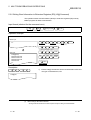
MELSEC-Q
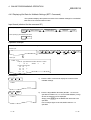
4.4.2 Displaying Set Data for Multitask Settings (SET? Command)
This operation displays the specified contents of the multitask settings for each BASIC
task area of the communication module.
Input format (shortcut for the command S?)
When specifying one of the BASIC task areas
SET?
SP
Specifying memory
location display
,
BASIC task No.
,
Device to be
displayed
Enter
Command
When specifying all the BASIC task areas
SET?
Enter
Command
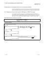
Operation example
Display the specified contents of the multitask settings for BASIC task No. 1 area of the communication module.
Before input
S>
S
E
T
Command
?
SP
1
BASIC
task No.
,
L
,
Memory location
display
R
Enter
DRAM
After input
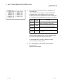
S>SET 1,L,R
Task No. Type Size Start Condition Start No. Location
1
IP 16
START
2
48
Location Size Task No.
48
16
1
64
32
5
96
16
112
16
2
Description
E
S
T
?
1)
Enter the SET? command to display the contents of the
multitask settings.
2)
Enter the target BASIC task area (task No. 1 to 8 can be
specified for AD51H-S3, 1 or 2 for A1SD51S/QD51 (-R24))
whose the set data is to be displayed.
Simply press Enter if all the BASIC task areas are to be
specified.
In the example figure to the left, BASIC task No. 1 is
specified.
S>SET?
SP
1
S>SET? 1
4 - 21
O
Enter
4 - 21
4 ONLINE PROGRAMMING OPERATION
,
L
3)
Enter L if the location allocation of each task is to be
displayed when booted to RAM.
Simply enter "," if the location allocation is not to be
displayed.
The following information is displayed:
• Head location
• Size
• BASIC task No.
4)
Enter the device (U/R) whose multitask settings are to be
displayed.
S>SET? 1,L
,
R
O
Enter
S>SET? 1,L,R
MELSEC-Q
U : Display the multitask settings of a user ROM.
R : Display the multitask settings booted on the current
RAM.
4 - 22
4 - 22
4 ONLINE PROGRAMMING OPERATION
5)
MELSEC-Q
The screen displays the result of the command execution.
If the command ends normally, the multitask settings of the
specified task area as well as the location allocation of each
task number are displayed from the succeeding line.
S>SET? 1,L,R
Task No. Type Size Start Condition Start No. Location
1
IP 16
START
2
48
Location Size Task No.
48
16
1
64
32
5
96
16
112
16
2
If the command ends abnormally, an error message or
similar is displayed in the succeeding line. The following
information is displayed when the command ends normally
(in the example figure to the left, the settings for BASIC task
No. 1 area are displayed). See the SET command
explanation page for the meaning of each item of
information displayed.
• Task No. : Task number of the task area displayed.
• Type
: This corresponds to the IP/CP specification
entered immediately after the startup condition
is set with the SET command.
• Size
: Size of the target task area. This corresponds
to the "task size" specified by the SET
command.
• Start
: The condition under which a BASIC program
Condition starts running in the target area. This
corresponds to the "startup condition" specified
by the SET command.
• Start No. : The execution startup order when START is
set as the startup condition attribute
( 4) above). This corresponds to the "startup
order" specified by the SET command.
If the startup condition is different from the
"START" attribute, the setting in this item is
meaningless, and "-" is displayed.
• Location : This shows the memory location allocated for
the task (in case of type CP only).
4 - 23
4 - 23
4 ONLINE PROGRAMMING OPERATION
6)
(2)
"S>" is displayed in the line following the command
execution result.
Enter the next command.
Reference
• Operation for saving information from BASIC task areas in the
communication module to a memory card/EEP-ROM/flash
ROM
• Operation for specifying the multitask settings/change the
already set data
• Operation for changing the mode of the communication
module to the edit mode (1)
4 - 24
MELSEC-Q
: MSAVE command (Section 4.3.2)
: SET command (Section 4.4.1)
: START command (Section 4.5.1)
4 - 24
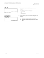
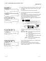
4 ONLINE PROGRAMMING OPERATION
MELSEC-Q
4.5 Operating Procedure for Changing the Mode of the Communication Module
This section explains how to use each of the system commands for controlling modes
and the operating procedure to change the mode of the communication module.
4.5.1 Changing the Mode of the Communication Module to the Edit Mode (1)
(START Command)
This operation allows the user to edit and debug each of the BASIC programs.
Input format (shortcut for the command ST)
When setting/changing the size of the target task area
START
SP
Basic task No.
Task size
,
Enter
Command
When the size of the target task area is not to be changed
START
SP
Enter
Basic task No.
Command
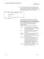
Operation example 1
Start editing a new BASIC program in the area of BASIC task No. 1. The size of the area of task No. 1 is set to 48 K bytes.
Before input
S>
S
T
A
R
T
Command
1
SP
,
Task No.
4
8
Enter
Task size
After input
S>START 1,48
If the interpreter has not been started, the following message is displayed
immediately before OK:
"AD51H-BASIC ON-LINE PROGRAMMING Ver
"
OK
Cursor
Operation example 2
Start editing and debugging the BASIC program in the area of task No. 1. The size of the area of task No. 1 is changed to 64 K bytes.
Before input
S>TKILL 1:
KILL OK
S>
S
T
A
Command
R
T
SP
1
Task No.
,
6
4
Enter
Task size
After input
S>TKILL 1:
KILL OK
S>START 1,64
OK
4 - 25
If the interpreter has not been started, the following message is displayed
immediately before OK:
"AD51H-BASIC ON-LINE PROGRAMMING Ver
"
4 - 25
4 ONLINE PROGRAMMING OPERATION
MELSEC-Q
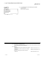
Description
S
T
A
R
T
SP
1)
Enter the START command to switch the mode of the
communication module into edit mode (1).
2)
Enter the task number (task No. 1 to 8 can be specified for
AD51H-S3, 1 or 2 for A1SD51S/QD51 (-R24)) of the task
area in which a BASIC program is to be edited/debugged.
The task number may be omitted.
If omitted, it is assumed that the next task number is
specified.
• When the START command is entered for the first time, it
is assumed that "1" is specified.
• If the START command has already been used, it is
assumed that the task number specified by the last
START command is specified.
In the example figure to the left, the BASIC program in the
area of task No. 1 will be edited/debugged.
S>START
S
S>START 1
4 - 26
4 - 26
4 ONLINE PROGRAMMING OPERATION
,
4
8
Onter
E
3)
Enter one of the following numerical values in order to
set/change the task size of the target task area (in K byte
units)
16, 32, 48, 64
The task size entered here will be the size set in the
automatic multitask setting, which is specified when saving
the contents of the target BASIC task area to a memory
card/EEP-ROM with the MSAVE command after the
completion of the BASIC program editing/debugging.
Make sure to enter the task size if a BASIC task number
whose multitask settings have not already been specified
has been selected.
Also, make sure to enter the task size if the multitask
settings have already been specified, but the task size
change is required.
Simply press Enter if the task size already set is not to be
changed.
In the example figure to the left, the task size of the area of
BASIC task No. 1 is set/changed to 48 K bytes.
4)
The screen displays the result of the command execution.
If the command ends normally, the display shows in the
figure to the left; the BASIC program can be
edited/debugged.
The operating procedure for editing/debugging BASIC
programs is explained in the AD51H-BASIC Programming
Manual.
If the command ends abnormally, an error message or
similar is displayed in the succeeding line.
The upper figure to the left shows the display when the
interpreter has not been started.
The lower figure to the left shows the display when the
interpreter has already been started.
S>START 1,48
AD51H-BASIC ON-LINE PROGRAMING Ver
OK
Or
OK
(1)
About the size specification
• Sizes can be specified in hexadecimal digits ("&H
instead of decimal digits.
4 - 27
MELSEC-Q
") or binary digits ("&B
to
")
4 - 27
4 ONLINE PROGRAMMING OPERATION
5)
SYSTEM
S>
(2)
MELSEC-Q
Perform one of the following operations when the
editing/debugging of the BASIC program is completed and
the communication module is returned from edit mode (1) to
system mode.
[Execute the SYSTEM instruction of BASIC program to
stop]
• The execution of the BASIC program is stopped.
• All open files and communication lines are closed.
[Press Ctrl + D ]
• The execution of the BASIC program is stopped.
• Open files and communication lines are kept open.
• If the BASIC program whose execution was stopped did
not require modification, its execution can be restarted
(continued) with the CONT instruction of the Basic
program when the START command is used to change
the mode to edit mode (1) again.
Precautions when using the START command
• In cases where a BASIC program is edited/debugged in a task area that falls into one of the
categories listed below and the task size must be changed, the operation of the interpreter in the
target task area should be terminated using the TKILL command before entering the START
command.
1) Task areas whose multitask settings have been specified
2) Task areas where BASIC programs are already stored
In addition, if the task size is increased, the following tasks should be performed once again when
saving a BASIC program to the execution area of a memory card/EEP-ROM/flash ROM (MSAVE
command) after the completion of editing and debugging.
1) All the executable programs should be saved again in the execution area of the memory card.
2) The set data of the multitask settings should be changed accordingly.
(Set each task size in such a way that the maximum 8 units of executable programs can be
saved within the executable program area size specified when the target memory card was
formatted.)
(3)
About debugging BASIC programs after the START command execution
• Debug BASIC programs in edit mode (1) according to the method explained in the programming
manual.
• The debug commands listed in Chapter 4 cannot be used.
(4)
Reference
• Operation for saving task area information from the main
memory to a memory card
• Operation for changing the mode of the communication
module
• Operation for ending the interpreter operation in the specified
task area
4 - 28
: MSAVE command (Section 4.3.2)
: GO command (Section 4.5.2)
: TKILL command (Section 4.6)
4 - 28
4 ONLINE PROGRAMMING OPERATION
MELSEC-Q
4.5.2 Changing the Mode of the Communication Module to Execution Mode/System Mode
(GO Command)
This operation changes the mode of the communication module from system mode to
execution mode/debug mode/execution mode (2), or changes it back to system mode.
By changing to debug mode, it becomes possible to debug each BASIC program
executed with the multitask settings by entering debug commands to the debugger
terminal (see Chapter 5).
By changing to execution mode (2), each BASIC program starts running according to
the multitask settings.
By changing back to system mode, it becomes possible to edit/debug each BASIC
program by entering system commands to the console.
The following table lists the relationship between the mode and debugging start
specification when the GO command is entered, and the statuses of the console and
the debugger terminal after the GO command has been executed.
Mode setting
R
(Execution mode (1))
Debugging startup
specification
Yes/No
Yes
(To debug mode)
No
(To execution mode (2))
P
(System mode within
programming mode)
Cannot be specified.
(1)
Console status
The contents of the
display are deleted. The
console display changes
to the one used for BASIC
programs.
The contents of the
display are deleted and
"S>" is displayed. It
becomes possible to enter
system commands.
Status of debugger
terminal
The debugger initiates, the
contents of the display are
deleted, and "D>" is
displayed. It becomes
possible to enter debug
commands.
The contents of the
display are kept as is. The
terminal becomes a
general-purpose port for
BASIC programs.
Remarks
Each BASIC program is
reloaded to the
corresponding task area
according to the multitask
settings, and is executed.
BASIC programs in each
task area stop being
executed.
Status of each BASIC program due to execution of the GO command
• If execution mode (1) is specified, each BASIC program starts executing in the same way as if the
communication module was started up by setting mode switch 1 of the communication module from
[0] to [3].
• If programming mode is specified, the BASIC programs in each task area stop being executed.
The memory status of each task area in the main memory has not changed, so the BASIC
programs in each task area remain as they are.
4 - 29
4 - 29
4 ONLINE PROGRAMMING OPERATION
MELSEC-Q
Input format (shortcut of the command None)
When changing the mode of the communication module to the debug mode
GO
SP
Command
R
,
Execution mode
D
Enter
Start up
the debugger
When changing the mode of the communication module to the execution mode
GO
SP
Command
Enter
R
Execution mode
Operation example
Change the mode of the communication module to debug mode.
Before input
S>
G
O
Command
SP
R
,
D
Enter
Specification to start up the debugger
Execution mode specification
After input
S>GO R,D
The content of the display is deleted.
Description
G
O
SP
1)
Enter the GO command to change the mode of the
communication module.
2)
Enter the mode.
Enter R to change to execution mode.
Enter R, D to change to debug mode.
In the example figure to the left, the mode of the
communication module is changed to debug mode.
S>GO
R
,
S>GO R,D
4 - 30
D
O
Enter
4 - 30
4 ONLINE PROGRAMMING OPERATION
3)
MELSEC-Q
The screen displays the result of the command execution.
If the command ends normally, the display shows as follows
depending on the specifications.
If the command ends abnormally, an error message or
similar is displayed in the succeeding line.
The example below illustrates the contents of the display when the command ends
normally.
1) When the mode is changed to the debug mode
(Debugger side)
(Console side)
The content of the display during the GO
command execution
D>
S>GO R,D
The content of the display is deleted.
(Waits for debug command input)
2)
(Becomes a console for BASIC programs)
When the mode is changed to the execution mode
The content of the display during the GO
command execution
The content of the display during the GO
command execution
(Becomes a general-purpose port
for BASIC programs)
(2)
• Enter debug commands from the
debugger in order to debug BASIC
programs.
• See Chapter 5 for an explanation of
the debug commands.
• The console can be used for BASIC
programs.
S>GO R
The content of the display is deleted.
• The debugger and console can
both be used for BASIC
programs.
(Becomes a console for BASIC programs)
About changing the modes of the communication module
• See Section 2.3 for the mode change diagram of the communication module.
(3)
Reference
• Operation for displaying the main menu screen on the
console
4 - 31
: EXIT command (Section 4.7)
4 - 31
4 ONLINE PROGRAMMING OPERATION
MELSEC-Q
4.6 Ending the Interpreter Operation in the Specified Task Areas (TKILL Command)
This section explains how to use the system command TKILL for controlling the
interpreter operation and the operating procedure to end the operation of the
interpreter in specified task areas.
Input format (shortcut for the command TK)
TKILL
SP
Enter
Task No.
Command
Operation example
End the operation of the interpreter in the area of BASIC task No. 1.
Before input
S>
T
K
I
Command
L
L
SP
1
Enter
Task No.
After input
S>TKILL 1
KILL OK
S>
Description
T
K
I
1
Enter
S>TKILL 1
4 - 32
L
L
SP
1)
Enter the TKILL command to end the operation of the
interpreter in the specified task area or one of the tasks
(task No. 1 to 8 can be specified for AD51H-S3, 1 or 2 for
A1SD51S/QD51 (-R24)) of the target task area.
The example figure to the left shows how to end the
operation of the interpreter in the area of task No. 1.
4 - 32
4 ONLINE PROGRAMMING OPERATION
2)
S>TKILL 1
KILL OK
S>
MELSEC-Q
The screen displays the result of the command execution in
the succeeding line.
If the command ends normally, "TKILL OK" is displayed.
If the command ends abnormally, an error message or
similar is displayed.
In the example figure to the left, a display where the
command ends normally is shown.
3) "S>" is displayed in the line following the command execution
result.
Enter the next command.
(1)
Usage of the TKILL command
The operation of the interpreter should be ended in the target task area before executing the GO
command when performing the following operations.
1) Change the mode of the communication module to system mode and change the task size of a
task area using the system commands START/SET.
2) Change the mode of the communication module to system mode and load executable
programs from the specified BASIC task area in a memory card/EPP-ROM to the target task
area of the communication module using the system command MLOAD.
(2)
Reference
• Operation for changing the mode of the communication
module to edit (1) mode
• Operation for changing the mode of the communication
module
4 - 33
: START command (Section 4.5.1)
: GO command (Section 4.5.2)
4 - 33
4 ONLINE PROGRAMMING OPERATION
MELSEC-Q
4.7 Operating Procedure for Displaying the Main Menu Screen on the Console
(EXIT Command)
This section explains how to use the EXIT command to display the main menu screen
on the console.
Input format (shortcut for the command E)
EXIT
Enter
Command
Operation example
Display the main menu screen on the A7PHP being used as a console.
Before input
S>
E
X
I
T
Enter
Command
After input
[Menu]
[Programming]
1. Online programming
2. Offline programming
Esc:Clase
Description
E
X
I
T
Enter
1)
Enter the EXIT command to display the main menu screen.
S>EXIT
(1)
Status of each BASIC program by the execution of the EXIT command
The BASIC programs in each BASIC task area execute continuously even when the EXIT command
is executed.
(2)
Precaution when entering the command
Stop the execution of BASIC programs before entering the EXIT command so that the execution does
not interfere with the system control when displaying the main menu to edit BASIC programs in each
BASIC task area, etc.
4 - 34
4 - 34
4 ONLINE PROGRAMMING OPERATION
2)
The screen displays the result of the command execution;
the user can perform necessary operations from this point.
If the command ends normally, the main menu screen is
displayed on the console; select a displayed item to perform
a necessary operation.
The content is displayed when the command ends normally.
See the following manual for an explanation of the
operations from the main menu screen:
SW1IVD-AD51HP/ SW1NX-AD51HP AD51H-BASIC
Operating Manual
[Menu]
[Programming]
1. Online programming
2. Offline programming
(2)
MELSEC-Q
If the command ends abnormally, an error message or
similar is displayed.
About changing the mode of the communication module
See Section 2.3 for the mode change diagram of the communication module.
(3)
Reference
Operation for changing the mode of the communication module : GO command (Section 4.5.2)
4 - 35
4 - 35
4 ONLINE PROGRAMMING OPERATION
MELSEC-Q
4.8 Operating Procedure for Checking the Input Formats of the System Commands (HELP
Command)
This section explains how to use the system command HELP to display the input
format, etc. of each of the system commands on the console.
Input format (shortcut for the command H)
HELP
Enter
Command
Operation example
Display input format, etc. of each system command.
Before input
S>
H
E
L
P
Enter
Command
After input
S>H
( 1)CCOPY Memory Card Copy CC {Source Drive No.:}
,{Destination Drive No.:}
[,V]
( 2)CFORMAT Memory Card Format CF {Drive No.:}
Description
H
E
L
P
Enter
1)
Enter the HELP command to display input format, etc. of
each system command.
S>HELP
4 - 36
4 - 36
4 ONLINE PROGRAMMING OPERATION
2)
MELSEC-Q
The screen displays the result of the command execution.
If the command ends normally, functions/input formats of
nine types of the system commands are displayed from the
succeeding line.
S>H
( 1)CCOPY Memory Card Copy CC {Source Drive No.:}
,{Destination Drive No.:}
[,V]
( 2)CFORMAT Memory Card Format CF {Drive No.:}
Press any key other than ESC to display functions/input
formats of system commands in the suceeding page (3
types). Press the ESC key to end the HELP command.
(Example)
(1) COPY Memory Card Copy CC {Source Drive No.}:
Command Function of command
Number for description
{Destination Drive No.}:
[,V]
Description of input format
(shortcut for command)
If the command ends abnormally, an error massage or
similar is displayed in the succeeding line. See Section 3.9
for error handling.
3)
(1)
"S>" is displayed in the line following the command
execution result.
Enter the next command.
About displaying the command input format
A one column space entered immediately after a command indicates the entry of the SP key (space).
Brackets ("{" and "}") are symbols that indicate separation of command arguments; it is not necessary
to enter brackets.
Square brackets ("[" and "]") are symbols that indicate that the arguments inside them are optional; it is
not necessary to enter square brackets.
4 - 37
4 - 37
4 ONLINE PROGRAMMING OPERATION
MELSEC-Q
4.9 Recovering an Area in Unusable File Area in a Memory Card (CRECOVER Command)
For AD51H-S3 Only
This operation locates a data area that is in the unusable status in the file area of a
memory card mounted in the specified drive and recovers it to the usable status again.
Input format (shortcut of the command CR)
CRECOVER
SP
:
Memory card interface No.
Enter
Command
Operation example
Recover an unusable file area in the memory card mounted in the modules MEMORY CARD 1 .
Before input
S>
C
R
E
C
O
Command
After input
V
E
R
SP
0
:
Memory card
interface No.
Enter
S>CRECOVER 0:
RECOVER(Y/N)?Y
RECOVER OK
S>
Description
C
R
R
SP
E
C
O
V
E
1)
Enter the CRECOVER command to recover a file area of a
memory card.
2)
Enter the memory card interface number of the memory card
whose file area is to be recovered followed by a colon (:).
Only 0 or 1 can be specified for the memory card interface
number.
0 : The MEMORY CARD 1 drive on the AD51H-S3.
S>CRECOVER
0
:
O
Enter
S>CRECOVER 0:
1 : The MEMORY CARD 2 drive on the AD51H-S3.
In the example figure to the left, the memory card mounted
on MEMORY CARD 1 is specified.
4 - 38
4 - 38
4 ONLINE PROGRAMMING OPERATION
Y
Enter
3)
The screen displays "RECOVER (Y/N)?"
Enter Y to recover.
Enter N to stop recovering. (The console returns to waiting
for a system command entry.)
In the example figure to the left, recovery is specified.
4)
The screen displays the result of the command execution in
the succeeding line.
If the command ends normally, "RECOVER OK" is
displayed.
If the command ends abnormally, an error message or
similar is displayed.
In the example figure to the left, a display where the
command ends normally is shown.
5)
"S>" is displayed in the line following the command
execution result.
Enter the next command.
S>CRECOVER 0:
RECOVER(Y/N)?Y
S>CRECOVER 0:
RECOVER(Y/N)?Y
RECOVER OK
S>
4 - 39
MELSEC-Q
4 - 39
4 ONLINE PROGRAMMING OPERATION
MELSEC-Q
4.10 Formatting (Logical Format) the File Area of a Memory Card (FFORMAT Command)
For AD51H-S3 Only
This operation formats (logically) the file area of a memory card mounted in MEMORY
CARD 1 or 2 on the AD51H-S3.
Input format (shortcut of the command FFM)
FFORMAT
SP
:
Memory card interface No.
Enter
Command
Operation example
Format the memory card mounted in MEMORY CARD 1 .
Before input
S>
F
F
O
R
M
Command
Enter
After input
Y
A
T
SP
0
:
Memory card
interface No.
Enter
Format
specification
S>FFORMAT 0:
FORMAT(Y/N)?Y
FORMAT OK
S>
Description
F
F
O
R
M
A
T
1)
Enter the FFORMAT command to format a memory card.
2)
Enter the memory card interface number in which the
memory card to be formatted is mounted followed by a
colon (:). Only 0 or 1 can be specified.
0 : The MEMORY CARD 1 drive of the AD51H-S3.
S>FFORMAT
SP
0
:
Onter
E
S>FFORMAT 0:
1 : The MEMORY CARD 2 drive of the AD51H-S3.
In the example figure to the left, the memory card mounted
in MEMORY CARD 1 is specified.
(1)
Precautions when using the FFORMAT command
• If a memory card is formatted, all data that was saved on it will be deleted.
• When formatting a memory card that is write-protected, the write protect should be canceled first.
• When formatting a memory card mounted in MEMORY CARD 1 , the memory protection key switch
of the AD51H-S3 module should be turned off first.
4 - 40
4 - 40
4 ONLINE PROGRAMMING OPERATION
Y
Enter
3)
The screen displays "FORMAT (Y/N)?"
Enter Y to format.
Enter N to stop formatting.
In the example figure to the left, formatting is specified.
4)
The screen displays the result of the command execution in
the succeeding line.
If the command ends normally, "FORMAT OK" is displayed.
If the command ends abnormally, an error message or
similar is displayed.
In the example figure to the left, a display where the
command ends normally is shown.
5)
"S>" is displayed in the line following the command
execution result.
Enter the next command.
S>FFORMAT 0:
FORMAT(Y/N)?Y
S>FFORMAT 0:
FORMAT(Y/N)?Y
FORMAT OK
S>
(2)
MELSEC-Q
Reference
Operation for physically formatting a memory card : CFORMAT command (Section 4.2.2)
4 - 41
4 - 41
5 MULTITASK DEBUGGING OPERATIONS
MELSEC-Q
5 MULTITASK DEBUGGING OPERATIONS
Multitask debugging refers to operations for finding and correcting errors in each
program while executing multiple BASIC programs at the same time.
This chapter explains how to use the debug commands entered from the debugger in
order to start executing BASIC programs with multitask settings and debug each
BASIC program.
5
(1)
This chapter mainly explains the key inputs and displays on the debugger side.
It is therefore generally omitted to state this fact explicitly for most key inputs and displays.
When necessary, it is pointed out explicitly that key inputs and displays are on the console side.
(2)
It is necessary to perform the following tasks in advance in order to perform the multitask debugging
described in this chapter.
Perform each operation beforehand according to the explanation in the applicable chapters/sections
below.
• Setting the switches of the communication module for debugging : See Chapter 2
• Connecting the debugger terminal
: See Chapter 2.
• Creating and debugging each individual BASIC program
: See Chapter 4.
• Saving the programs to a memory card
See Section 4.3.2.
• Specifying multitask settings
: See Section 4.4.1.
(4)
5-1
Precautions when entering the debug commands
If the debugger function (an OS that analyzes and executes debug commands) cannot immediately
process a command the user has entered, the debugger function suspends operation until the
processing can be resumed.
The next debug command can be entered after "D>" is displayed again.
5-1
5 MULTITASK DEBUGGING OPERATIONS
MELSEC-Q
5.1 Debug Command List
Table 5.1 lists the debug commands used in multitask debugging operations.
Table 5.1 Debug Command List
A1SD51S
QD51
(-R24)
Reference
section
Starts executing the BASIC program residing in the specified task area.
Section 5.2.2
Stops executing the BASIC program currently being executed in the
specified task area.
Section 5.2.3
TCONTINUE
1
Resumes executing the BASIC program in the specified task area that
has been stopped.
Section 5.2.4
T?
Displays values of specified variables in the BASIC program residing in
the specified task area.
Section 5.2.5
Assigns value to specified variables in the BASIC program residing in
the specified task area.
Section 5.2.6
Displays values of specified address ranges in
memory that can be shared by different BASIC
programs.
Section 5.3.1
1
1
TSTOP
1
1
TLET
1
• Buffer memory
• Main memory
• Extension relays
(EM)
Writes values to specified addresses in memory
• Extension registers
that can be shared by different BASIC
(ED)
programs.
MREAD
MWRITE
Displays bit information of an internal device that • General-purpose
can be shared by input/output signals to the
inputs (X)
PLC CPU as well as BASIC programs.
• General-purpose
outputs (Y)
Writes bit information to an internal device that
• Extension relays
can be shared by input/output signals to the
(EM)
PLC CPU as well as BASIC programs.
B@
Memory access
control
B@
Displays word information of an internal device
that can be shared by different BASIC
programs.
W@
Writes word information to an internal device
that can be shared by different BASIC
programs.
W@
OS information
ZSTATUS
check
START
Mode control
GO
Others
AD51HS3
Section 5.2.1
TRUN
5
Function overview
Displays the status of the BASIC program residing in the specified task
area.
TSTATUS
Task control
Availability for module
System
command
Classification
1
Section 5.3.2
Section 5.3.3
Section 5.3.4
Section 5.3.5
• Extension registers
(ED)
Section 5.3.6
Displays usage statuses of events/message ports/resources that can be
shared by different BASIC programs.
Section 5.4.1
Section 5.4.2
Section 5.4.3
Changes the mode of the communication module from debug mode to
edit mode (2). (For program editing during multitask execution)
Section 5.5.1
Changes the mode of the communication module from debug mode to
system mode/execution mode (2), or changes back to debug mode.
Section 5.5.2
EXIT
Displays the main menu screen on the debugger terminal.
Section 5.6
HELP
Displays the list of debug commands, function overviews, and
command input formats.
Section 5.7
1 These commands cannot be executed on tasks in which compiled BASIC programs reside.
5-2
5-2
5 MULTITASK DEBUGGING OPERATIONS
MELSEC-Q
5.2 Operations for Controlling the Operation of BASIC Programs
This section explains how to use each of the debug commands for controlling tasks
and the operating procedure to control the operation of BASIC programs.
5.2.1 Displaying the Status of the Specified BASIC Program (TSTATUS Command)
This operation displays the status of the BASIC program in the specified task area.
Input format (shortcut for the command TS)
When specifying one of the task areas
TSTATUS
SP
Task No.
Enter
Command
When specifying all the task areas
TSTATUS
Enter
Command
Operation example
Display the status of the BASIC program in the area of task No.1.
Before input
D>
T
S
T
A
Command
T
U
S
SP
1
Enter
Task No.
After input
D>TSTATUS 1
TASK NO STATUS PRIORITY STEP NO
1
WAIT
1
150
Description
T
S
T
A
T
U
S
1)
Enter the TSTATUS command to order to display the status
of a BASIC program.
S>TSTATUS
5-3
5-3
5 MULTITASK DEBUGGING OPERATIONS
SP
1
O
Enter
MELSEC-Q
2)
Enter the task number (task No. 1 to 8 can be specified for
AD51H-S3, 1 or 2 for A1SD51S/QD51 (-R24)) of the task
area whose status is going to be displayed.
Simply press Enter if all task areas are to be displayed.
In an example figure to the left, task No. 1 is specified.
3)
The screen displays the result of the command execution in
the next line.
If the command ends normally, the status of the BASIC
program in the specified task area is displayed in the center
of the display.
If the command ends abnormally, "TSTATUS: Error" and an
error code are displayed in the succeeding line.
The following information is displayed when the command
ends normally. (In an example figure to the left, the status of
the area of task No. 1 is displayed.)
• TASK NO : Task number of the task area whose status
is displayed.
• STATUS : Status of the BASIC program
DORMANT: The interpreter has not been
started in the target area.
RUN: The program is being executed.
WAIT: In waiting status. (Waiting for a
timeout, etc.)
STOP: The program is not being executed.
The interpreter is waiting for command
entry. ( 1)
• PRIORITY : Current priority of the BASIC program.
The value 0 is displayed if [STATUS] above
is DORMANT.
• STEP ON : The current line number being executed.
The number of the last executed line is
displayed If [STATUS] above is STOP. If it
is DORMANT, the value 0 is displayed.
4)
"D>" is displayed in the line following the command
execution result.
Enter the next command.
S>TSTATUS 1
D>TSTATUS 1
TASK NO STATUS PRIORITY STEP NO
1
WAIT
1
150
1: The program is also forced into the STOP status when
the execution of the specified BASIC program is
stopped using the debug command "TSTOP."
5-4
5-4
5 MULTITASK DEBUGGING OPERATIONS
MELSEC-Q
5.2.2 Starting the Execution of the Specified BASIC Program (TRUN Command)
This operation starts the execution of the BASIC program residing in the specified task
area.
Input format (shortcut of the command TR)
TRUN
SP
Task No.
Enter
Command
Operation example
Start execution of the BASIC program residing in the area of task No. 1.
Before input
D>
T
R
U
Command
N
SP
1
Enter
Task No.
After input
D>TRUN
Description
T
R
U
N
SP
1
Enter
1)
Enter the TRUN command to order to start executing a
BASIC program along with the task number (task No. 1 to 8
can be specified for AD51H-S3, 1 or 2 for A1SD51S/QD51
(-R24)) of the task area where the target program resides.
In an example figure to the left, the BASIC program residing
in the area of task No. 1 starts executing.
2)
The screen displays the result of the command execution in
the succeeding line.
If the command ends normally, "REQUEST OK" is
displayed.
If the command ends abnormally, an error message and
error code are displayed.
In an example figure to the left, a display where the
command ends normally is shown.
D>TRUN 1
D>TRUN 1
REQUEST OK
5-5
5-5
5 MULTITASK DEBUGGING OPERATIONS
3)
(1)
MELSEC-Q
"D>" is displayed in the line following the command
execution result.
Enter the next command.
Precautions when entering the command
• If a task area is specified in which a BASIC program is already being executed, an error occurs.
If there is no BASIC program in the specified task area, an error occurs.
(2)
Reference
• Operation for stopping the execution of the specified
BASIC program
: TSTOP command (Section 5.2.3)
5-6
5-6
5 MULTITASK DEBUGGING OPERATIONS
MELSEC-Q
5.2.3 Stopping the Execution of the Specified BASIC Program (TSTOP Command)
This operation stops the execution of the BASIC program in the specified task area.
Input format (shortcut for the command TP)
When stopping at the line currently being executed
TSTOP
SP
Task No.
Enter
SP
Task No.
,
Command
When stopping at the specified line
TSTOP
Line number
Enter
Command
Operation example
Stop the execution at line 120 of the BASIC program being executed in the area of task No. 1.
Before input
D>
T
S
T
O
Command
1
2
P
SP
1
,
Task No.
0
Enter
Line number
After input
D>TSTOP 1,120
REQUEST OK
Description
T
S
D>TSTOP 1
5-7
T
O
P
SP
1
1)
Enter the TSTOP command to stop the execution of a
BASIC program along with the task number (task No. 1 to 8
can be specified for AD51H-S3, 1 or 2 for A1SD51S/QD51
(-R24)) of the task area where the target program is being
executed.
In an example figure to the left, the BASIC program being
executed in the area of task No. 1 stops executing.
5-7
5 MULTITASK DEBUGGING OPERATIONS
,
1
2
0
Enter
2)
Enter the line number of the BASIC program whose
execution is to be stopped using a decimal number.
Simply press Enter if it is desired to stop the execution at
the line currently being executed.
Note that if this command is entered again by specifying the
values 65535 or -1 as the line number before executing the
line specified by the line number entry, the first execution
stop specification is canceled.
In an example figure to the left, it is specified to stop
execution at line number 120.
3)
The screen displays the result of the command execution in
the next line.
If the command is received normally, "REQUEST OK" is
displayed.
In addition, the following stop message is displayed when
the BASIC program stops executing.
D>TSTOP 1,120
D>TSTOP 1,120
REQUEST OK
MELSEC-Q
BREAK:Task No.
Line No.
The line number at which
the execution was stopped.
The task number of the task area for which
the execution was stopped.
Note that if 65535 or -1 was specified as a line number and
the command was received normally, "BREAK Cancel: Task
No.
" is displayed.
If there was an error in the command entry, "Error" message
and an error code are displayed.
In an example figure to the left, a display where the
command ends normally is shown.
If the command ends normally, the target BASIC program
goes into the STOP status and the execution can be
resumed with the TCONTINUE command.
4)
(1)
"D>" is displayed in the line following the command
execution result.
Enter the next command.
Precautions when entering the command
• When specifying the line number, a line number that exists in a program should be entered using
the same decimal format as the description format in the program.
If a line number that does not exist in the program is entered, the program will not be stopped. In
this case, specify 65535 or -1 as a line number and enter this command again.
• It is only possible to specify one line number at which the execution should be stopped for any one
BASIC program in any one task area.
• The execution of a BASIC program should be stopped in such a way that it does not interfere with
the system control.
5-8
5-8
5 MULTITASK DEBUGGING OPERATIONS
(2)
MELSEC-Q
Reference
• Operation for checking the status of the current BASIC
program
• Operation for starting the execution from the start line
again
• Operation for resuming (continuing) execution from a line
at which execution was stopped
• Operation for checking values of specified variables
• Operation for assigning values to specified variable
(3)
: TSTATUS command (Section 5.2.1)
: TRUN command (Section 5.2.2)
: TCONTINUE command (Section 5.2.4)
: T? command (Section 5.2.5)
: TLET command (Section 5.2.6)
Operation of the TSTOP command
• If a line number is specified at the TSTOP command entry, the program execution is stopped before
executing the line with the specified number. Therefore, none of the instructions in the specified line
have been executed when the execution of the BASIC program is stopped by the command.
If a line number was not specified, the execution is stopped after the interpreter processes the
instruction that is being executed at the time of pressing the Enter key. Therefore, if multiple
instructions were entered in one line (multi-statement), the instructions after the instruction being
executed at the time the Enter key was pressed would not have been executed.
(4)
Precautions when stopping the execution of a BASIC program by entering the TSTOP
command
• When a BASIC program stops being executed with the TSTOP command, the debugger (OS)
displays a stop message at the current cursor position.
If the user enters the command while the debugger displays the stop message, the message and
command are mixed and both are displayed.
In this case, the command being entered is valid; continue entering the remaining text string of the
command entry.
(Example) If a stop message is displayed while entering the TSTATUS command:
D>TSTOP 1,190
REQUEST OK
D>TSTABreak:Task No.1 Line No 00180
Stop message
Command being entered
D>TSTOP 1,190
REQUEST OK
D>TSTABreak:Task No.1 Line No 00180
TUS 1
Command being entered
Enter the remaining string of
the command entry
(Enter TSTATUS 1 and press Enter .)
(5)
How to end the operation of the interpreter in the specified task area
• If the user wants to end the operation of the interpreter in the specified task area, the program
should be created in such a way as to execute the BASIC instruction "END."
5-9
5-9
5 MULTITASK DEBUGGING OPERATIONS
MELSEC-Q
5.2.4 Resuming the Execution of the Specified BASIC Program Whose Execution Has Been
Stopped (TCONTINUE Command)
This operation resumes the execution of the BASIC program in the specified task area
whose execution was stopped by the TSTOP command.
Input format (shortcut for the command TC)
When resuming execution from the instruction after the last instruction executed when the execution was stopped
TCONTINUE
SP
Task No.
Enter
Command
When resuming execution from the specified line number
TCONTINUE
SP
Task No.
,
Line number
Enter
Command
Operation example
Resume execution of the BASIC program in the area of task No. 1 which is currently being stopped, from line number 120.
Before input
D>TCONTINUE 1,120
T
C
O
N
T
Command
,
1
2
0
I
N
U
E
SP
1
Task No.
Enter
Line number
After input
D>TCONTINUE 1,120
REQUEST OK
D>
Description
T
C
O
N
U
E
SP
1
D>TCONTINUE 1
5 - 10
T
I
N
1)
Enter the TCONTINUE command in order to resume
execution of a BASIC program whose execution was
stopped by the TSTOP command and the task number (task
No. 1 to 8 can be specified for AD51H-S3, 1 or 2 for
A1SD51S/QD51 (-R24)) of the task area where target
program resides.
In an example figure to the left, the BASIC program in the
area of task No. 1 which is currently being stopped, is being
resumed.
5 - 10
5 MULTITASK DEBUGGING OPERATIONS
,
1
2
0
Enter
2)
Enter a line number from which execution is to be resumed
using a decimal number.
Simply press Enter if the execution should be resumed
from the instruction after the last instruction executed when
the execution was stopped.
In an example figure to the left, line number 120 is specified.
3)
The screen displays the result of the command execution in
the succeeding line.
If the command ends normally, "TCONTINUE: REQUEST
OK" is displayed.
If the command ends abnormally, "TCONTINUE: Error" and
an error code are displayed.
In an example figure to the left, a display where the
command ends normally is shown.
If the command ends normally, the BASIC program in the
specified task area is placed in the RUN status.
4)
"D>" is displayed in the line following the command
execution result.
Enter the next command.
D>TCONTINUE 1,120
D>TCONTINUE 1,120
REQUEST OK
D>
(1)
MELSEC-Q
Precautions when entering the command
• The TCONTINUE command can be executed on a BASIC program in the STOP status whose
execution was stopped by the TSTOP command.
An error occurs if the command is entered for a BASIC program that is in a status other than STOP.
In addition, if a task area that contains a BASIC program in the STOP status is specified, and the
mode of the communication module is changed to edit mode (2), the execution of this BASIC
program in the STOP status cannot be resumed using the TCONTINUE command. It cannot even
be resumed if the mode of the module is returned to debug mode by executing the SYSTEM
instruction.
The status of a BASIC program can be checked using the TSTATUS command.
(2)
Precautions when specifying a line number
• When specifying the line number, a line number that exists in a program should be entered using
the same decimal format as the description format in the program.
If a line number that does not exist in a program is entered, the execution is resumed from the line
with the first number after the specified number.
(3)
Reference
• Operation for checking the status of the current BASIC
program
• Operation for stopping the execution of the specified
BASIC program
• Operation for starting the execution from the start line
again
5 - 11
: TSTATUS command (Section 5.2.1)
: TSTOP command (Section 5.2.3)
: TRUN command (Section 5.2.2)
5 - 11
5 MULTITASK DEBUGGING OPERATIONS
MELSEC-Q
5.2.5 Displaying Values of Specified Variables in the Specified BASIC Program (T?
Command)
This operation displays the current value of the specified variable used in the BASIC
program in the specified task area.
Input format (shortcut for the command none)
T?
SP
Task No.
,
Sequence of
expressions
Enter
Command
Operation example
Display the current values of variables A$ and B% used in the BASIC program in the area of task No. 1, whose execution has been
stopped.
Before input
D>T? 1,A$;B%
T
?
Command
SP
1
Task No.
,
A
$
;
B
%
Enter
Sequence of expressions
After input
D>T? 1,A$;B%
51H=123
D>
Description
T
?
SP
1
,
;
B
%
1)
Enter the T? command in order to display the values of the
variables along with the task number (task No. 1 to 8 can be
specified for AD51H-S3, 1 or 2 for A1SD51S/QD51 (-R24))
of the task area where the target program resides.
In an example figure to the left, the BASIC program in task
No. 1 area is specified.
2)
Enter the name of the variables you want the values to be
displayed.
The variables can be specified as numerical or string
expressions in the same way as for the BASIC instruction
PRINT.
Moreover, several variables can be displayed by separating
the expressions by comma (,) or semicolon (;).
In an example figure to the left, it is specified to display the
values of A$ and B%.
D>T? 1,
A
$
D>T? 1,A$;B%
5 - 12
Enter
5 - 12
5 MULTITASK DEBUGGING OPERATIONS
3)
The screen displays the result of the command execution in
the succeeding line.
If the command ends normally, "T:? " and the values of the
specified variables, etc. are displayed.
If the command ends abnormally, "T?: Error" and an error
code are displayed.
In an example figure to the left, a display where the
command ends normally is shown. It indicates that A$
contains "51H=" and B% contains 123.
4)
"D>" is displayed in the line following the command
execution result.
Enter the next command.
D>T? 1,A$,B%
51H=123
D>
(1)
MELSEC-Q
Precautions when entering the command
• If you specify a BASIC program in the DORMANT status, an error occurs.
• The T? command, including the sequence of expressions, must be entered in such a way that the
entire command is contained in one line.
The expression order should furthermore be entered in such a way that the number of characters
displayed is 1,024 characters or less.
• It is recommended to place the target BASIC program in the STOP status using the TSTOP
command before entering the T? command.
(2)
Reference
• Operation for checking the status of the current BASIC
program
• Operation for stopping the execution of the specified
BASIC program
• Operation for resuming (continuing) execution from a
line at which execution was stopped
• Operation for assigning values to specified variables
5 - 13
: TSTATUS command (Section 5.2.1)
: TSTOP command (Section 5.2.3)
: TCONTINUE command (Section 5.2.4)
: TLET command (Section 5.2.6)
5 - 13
5 MULTITASK DEBUGGING OPERATIONS
MELSEC-Q
5.2.6 Assigning Values to Specified Variables in the Specified BASIC Program (TLET
command)
This operation assigns values to the specified variables used in the BASIC program in
the specified task area.
Input format (shortcut for the command TL)
TLET
SP
,
Task No.
Variable name
=
Expression
Enter
Command
Operation example
Assign values to variables A$ and B% used in the BASIC program area of task No. 1, whose execution has been stopped.
Before input
D>TLET 1,A$="12AB"
T
L
E
T
SP
Command
"
1
2
1
,
Task No.
A
B
A
$
=
Variable name
"
Enter
1
,
Expression (when entering constants)
After input
T
D>TLET 1,A$="12AB"
OK
D>
L
E
T
Command
1
2
3
SP
Task No.
B
%
=
Variable name
Enter
Expression
(when entering constants)
Description
T
L
E
T
SP
1
,
1)
Enter the TLET command in order to assign values to
variables along with the task number (task No. 1 to 8 can be
specified for AD51H-S3, 1 or 2 for A1SD51S/QD51 (-R24))
of the task area where the target program resides.
In an example figure to the left, the BASIC program in the
area of task No. 1 is specified.
2)
Enter the name of the variables to which the values are to be
assigned.
It is possible to specify names of array variables (e.g., C(0),
D$(1%)) in the same way as for the BASIC instruction LET.
In an example figure to the left, it is specified that a value is
assigned to character variable A$.
S>TLET 1,
A
$
=
S>TLET 1,A$=
5 - 14
5 - 14
5 MULTITASK DEBUGGING OPERATIONS
"
1
2
A
B
"
Enter
3)
Enter the value to be assigned.
The values to be assigned can be specified as numerical or
string expressions in the same way as for the BASIC
instruction LET.
In an example figure to the left, it is specified to assign
character constant "12AB" to character variable A$.
4)
The screen displays the result of the command execution in
the succeeding line.
If the command ends normally, "OK" is displayed.
If the command ends abnormally, "Error" message and an
error code are displayed.
In an example figure to the left, a display where the
command ends normally is shown.
5)
"D>" is displayed in the line following the command
execution result.
Enter the next command.
D>TLET 1,A$="12AB"
D>TLET 1,A$="12AB"
OK
D>
(1)
MELSEC-Q
Precautions when entering the command
• An error will occur if a BASIC program in the DORMANT status is specified.
• It is recommended to place the target BASIC program in the STOP status using the TSTOP
command before entering the TLET command.
(2)
Reference
• Operation for checking the status of the current BASIC
program
• Operation for stopping the execution of the specified
BASIC program
• Operation for resuming (continuing) execution from a
line at which execution was stopped
• Operation for checking values of specified variables
5 - 15
: TSTATUS command (Section 5.2.1)
: TSTOP command (Section 5.2.3)
: TCONTINUE command (Section 5.2.4)
: T? command (Section 5.2.5)
5 - 15
5 MULTITASK DEBUGGING OPERATIONS
MELSEC-Q
5.3 Internal Memory Read/Write Operations
This section explains how to use each of the debug commands for controlling memory
access and the operating procedure for reading/writing from/to the module’s internal
memory.
Internal memory
Communication
module
Buffer memory
6 K bytes
Common memory
8 K bytes
Extension registers (ED0 to ED1023)
1024 points (1024 words)
1024 points (1024 bits)
Extension relays (EM0 to EM1023)
X0 to X1F
General-purpose I/O
Y0 to Y1F
32 points (32 bits)
32 points (32 bits)
The addresses are specified when accessing internal memory via the commands
MREAD and MWRITE, explained in this section. The figure below illustrates the
relationship between addresses specified by these commands and internal memory.
Access should be made within the address range of each memory area.
0H
0000H
to
Buffer memory
(6K bytes)
17FFH
1800H
to
37FFH
3800H
to
3FFFH
to
BFFH
Common memory
(8K bytes)
ED0-ED1023
(1024 words)
Address specified when accessing memory from
the PLC CPU using the FOM/TO commands.
Memory is accessed assuming 1 address = 2 bytes.
3800H
3801H
3802H
3803H
to
(L)
(H)
(L)
(H)
ED0
ED1
to
3FFEH (L)
ED1023
3FFFH (H)
Address specified by debug commands.
Memory is accessed assuming 1 address = 1 byte.
5 - 16
5 - 16
5 MULTITASK DEBUGGING OPERATIONS
MELSEC-Q
5.3.1 Displaying Values of Buffer Memory/Common Memory/Extension Registers (ED)
(MREAD Command)
This operation displays the values currently stored in specified memory, which can be
either buffer memory, common memory, or extension register (ED).
Input format (shortcut for the command MR)
When displaying the values stored in memory in byte units
MREAD
SP
,
Starting address
Number of
bytes displayed
Command
SP
B
Enter
Byte units
(omissible)
When displaying the values stored in memory in word units
MREAD
,
Starting address
,
Number of
bytes displayed
Command
,
W
Enter
Word units
Operation example
Display the values stored in ED0 to ED5 in word units.
Before input
D>
M
R
A
E
D
Command
,
6
,
Number of
words displayed
SP
3
8
0
0
Starting address
W
Enter
Word units
After input
D>MREAD 3800,6,W
3800:0000 0000 0000 0000 0000 0000
D>
Description
M
R
E
A
8
0
0
,
Enter the MREAD command in order to display values
stored in device memory along with the starting address of
the memory range for which values are to be displayed
using a hexadecimal number up to 4 digits (0 to 3FFF).
The relationship between device memory and addresses is
shown in Section 13.3. In an example figure to the left,
address 3800H of ED0 is shown. An even number should be
specified for the least significant digit when displaying in
word units.
The specified address will not be displayed if the least
significant digit is an odd number.
SP
(1)
Precautions when entering the number of bytes/words to be displayed
D>MREAD 3800,
3
1)
D
• Enter the number of bytes/words to be displayed in such a way that it satisfies the following
condition:
Address + number of bytes/words displayed – 1 < 3FFFH
If addresses that exceed 3FFFH are specified, only the values stored in memory up to 3FFFH are
displayed.
5 - 17
5 - 17
5 MULTITASK DEBUGGING OPERATIONS
6
,
W
O
Enter
2)
Enter the number of bytes/words in the memory range
whose values are to be displayed along with the display
type.
If B (omissible) is specified as display type, enter the
number of bytes in the memory.
If W is specified as display type, enter the number of words
in the memory range. In either case, the number of
bytes/words should be entered as a hexadecimal number.
When specifying in number of bytes:
1H < (number of bytes) < 4000H
When specifying in number of words:
1H < (number of words) < 2000H
In an example figure to the left, 6 words are specified in
word units.
3)
The screen displays the result of the command execution in
the succeeding line.
If the command ends normally, the values stored in the
specified memory range are displayed in the specified units.
In case of byte units, the values stored in up to 16
addresses,
0 to
F, are displayed in one
line as shown below. Note that if the least significant digit of
the specified address is different from 0 (n) the values
displayed for
0 to
n-1 become blank.
D>MREAD 3800,6,W
D>MREAD 3800,6,W
3800:0000 0000 0000 0000 0000 0000
D>
:
The starting
address is
displayed.
MELSEC-Q
to
The values stored in each of
the 16 addresses starting from
the one shown to the left, in
sequence from the left, are
displayed as 2-digit
hexadecimal numbers.
Characters corresponding to
the values stored in each
address are displayed. "," is
displayed for 0H to 1FH.
In case of word units, the values stored in 16 addresses are displayed in one line as shown below.
:
to
The starting
address is
displayed.
The values stored in the 16 addresses
starting from the one shown to the left, in
sequence from the left, are displayed pairwise as 4-digit hexadecimal numbers.
If the command ends abnormally, "Error" message and an
error code are displayed.
In an example figure to the left, a display where the
command ends normally is shown.
4)
5 - 18
"D>" is displayed in the line following the command
execution result.
Enter the next command.
5 - 18
5 MULTITASK DEBUGGING OPERATIONS
(2)
MELSEC-Q
Operation when it is specified to display 17 or more lines
• The screen can display a maximum of 16 lines of values stored in memory. Press any key other
than ESC to display values from the subsequent address, if it is specified to display 17 or more
lines of values.
Press ESC if you want to stop displaying values stored in memory.
(3)
Reference
• Operation for writing values to specified memory
• Operation for checking word information in extension
registers ED
• Operation for writing word information to extension
registers ED
5 - 19
: MWRITE command (Section 5.3.2)
: W@ command (Section 5.3.5)
: W@ command (Section 5.3.6)
5 - 19
5 MULTITASK DEBUGGING OPERATIONS
MELSEC-Q
5.3.2 Writing Values to Buffer Memory/Common Memory/Extension Registers (ED)
(MWRITE Command)
This operation writes values to the specified memory, which can be either buffer
memory, common memory, or extension memory (ED).
Input format (shortcut for the command MW)
When writing values to memory in byte units
(one value per one address)
MWRITE
SP
Starting address
Command
,
When writing values to memory in word units
(one value per two addresses)
B
Enter
MWRITE
Byte units
(omissible)
SP
Starting address
,
Command
W
Enter
Word units
Operation example
Write the values (0AH, 14H, 1EH) to ED0 to ED2 in word units.
Before input
M
D>
W
R
I
T
E
Command
0
0
0
A
SP
3
8
0
Starting address
0
,
W
Enter
Write
type
Enter
Writing to addresses 3800H to 3801H (ED0)
After input
0
D>MWRITE 3800,W
3800:0000 000A
3801:0000 0014
3802:0000 001E
3803:0000 .
D>
0
1
4
Enter
Writing to addresses 3802H to 3803H (ED1)
0
0
1
E
Enter
Writing to addresses 3804H to 3805H (ED2)
Enter
.
0
Write end
Description
M
W
R
I
T
E
3
8
0
0
,
SP
1)
Enter the MWRITE command in order to write values to
device memory along with the memory address where the
writing should start using a hexadecimal number up to 4
digits (0 to 3FFF).
The relationship between device memory and addresses is
shown in Section 5.3.
In an example figure to the left, address 3800H of ED0 is
specified.
2)
Enter type of values to be written.
Enter B (omissible) to write the values in byte units.
Enter W to write the values in word units.
In an example figure to the left, it is specified to write in word
units.
D>MWRITE 3800,
W
Enter
D>MWRITE 3800,W
5 - 20
5 - 20
5 MULTITASK DEBUGGING OPERATIONS
3)
D>MWRITE 3800,W
3800:0000
0
0
0
A
MELSEC-Q
The screen displays the result of the command execution in
the succeeding line.
If the command ends normally, the specified address and
currently stored value are displayed with the specified units
in hexadecimal numbers.
In case of byte units, the display shows as follows; enter the
value to be written using a hexadecimal number with 2 digits
or less (only valid digits can be entered).
Enter
:
Enter the value to be written as a
hexadecimal number (for one address)
D>MWRITE 3800,W
3800:0000 000A
The value currently stored in the address to
the left is displayed as a 2-digit hexadecimal number.
The address is displayed.
In case of word units, the display shows as follows; enter
the value to be written using a hexadecimal number with 4
digits or less (only valid digits can be entered).
0
0
1
4
Enter
Enter the values to be written as a
hexadecimal number (for two addresses).
D>MWRITE 3800,W
3800:0000 000A
3801:0000 0014
The values currently stored in the two addresses
starting with the one shown to the left are displayed
as 4-digit hexadecimal numbers.
The address is displayed.
Address
nH
n+1H
0
0
1
E
D>MWRITE 3800,W
3800:0000 000A
3801:0000 0014
3802:0000 001E
.
Enter
Values to be displayed
or written
1 234
34(H)
12(H)
The following keys are used in the write operation:
0 to 9 , A to F : Used to enter the values to be written.
. : Used to write the entered values to
device memory.
¥ : Used when backing up the target
address.
Enter : Used when executing entries made
using the keys above.
Used when the value currently stored in
memory is not to be overwritten.
Enter
D>MWRITE 3800,W
3800:0000 000A
3801:0000 0014
3802:0000 001E
3803:0000.
D>
5 - 21
If the command ends abnormally, "Error" message and an
error code are displayed.
In an example figure to the left, a display where values are
written to memory addresses 3800H to 3805H (ED0 to ED2)
in word units successfully is shown.
5 - 21
5 MULTITASK DEBUGGING OPERATIONS
4)
(1)
MELSEC-Q
When writing to device memory is completed, "D>" is
displayed.
Enter the next command.
Operation when exceeding memory range of target device
• The processing of the MWRITE command is automatically terminated if the address of device
memory to which a value is written exceeds 3FFFH.
(2)
Reference
• Operation for checking values of specified memory
• Operation for checking word information of extension
registers ED
• Operation for writing word information to extension
registers ED
5 - 22
: MWRITE command (Section 5.3.1)
: W@ command (Section 5.3.5)
: W@ command (Section 5.3.6)
5 - 22
5 MULTITASK DEBUGGING OPERATIONS
MELSEC-Q
5.3.3 Displaying Bit Information of General-Purpose Inputs (X)/General-Purpose Outputs
(Y)/Extension Relays (EM) (B@ Command)
This operation displays bit information of general-purpose inputs (X)/outputs (Y) used
by the PLC CPU or extension relays (EM) used by BASIC programs for data
communication.
Input format (shortcut for the command none)
When displaying bit information of general-purpose inputs (X)
B@
(
Command
X
,
Number of
points displayed
)
Enter
Starting number
,
Number of
points displayed
)
Enter
Starting number
,
Number of
points displayed
)
Enter
6
,
Starting number
,
Device name
When displaying bit information of general-purpose outputs (Y)
B@
(
Command
Y
,
Device name
When displaying bit information of extension relays (EM)
B@
(
Command
EM
,
Device name
Operation example
Display bit information of EM16 to EM47.
Before input
D>
B
@
(
Command
3
2
E
M
Device name
)
,
1
Starting number
Enter
Number of
points displayed
After input
D>B@(EM,16,32)
EM0016:00000000-00000000
EM0032:00000000-00000000
D>
(1)
About general-purpose input/output devices between the PLC CPU and the communication
module
• General-purpose input/output devices handle bit information communicated between the sequence
programs on the PLC CPU side and the BASIC programs on the communication module side, as
well as bit information controlled by each OS.
5 - 23
5 - 23
5 MULTITASK DEBUGGING OPERATIONS
MELSEC-Q
Description
B
@
(
E
M
,
1)
Enter the B@ command to display bit information and the
type of the target device.
Enter the device type using the following characters.
X : When specifying general-purpose inputs
(PLC CPU Communication module)
Y : When specifying general-purpose outputs
(PLC CPU Communication module)
EM : When specifying extension relays
In an example figure to the left, extension relays are
specified.
2)
Enter the starting number of the target device range for
which the bit information is to be displayed.
Enter a hexadecimal number with 2 digits or less if X or Y
have been specified, or a decimal number with 4 digits or
less if EM has been specified.
X/Y: 0 to 1F EM: 0 to 1023
In an example figure to the left, EM16 is specified.
3)
Enter the number of points displayed (number of bits) of the
target device range for which bit information is to be
displayed using a decimal or hexadecimal number.
X/Y : 1 (1H) ≤ "number of points displayed" 32 ≤ (20H)
EM : 1 (1H) ≤ "number of points displayed" 1024 ≤ (400H)
In an example figure to the left, 32 points (32 bits) are
specified.
D>B@(EM,
1
6
,
D>B@(EM,16,
3
2
)
D>B@(EM,16,32)
5 - 24
Onter
E
5 - 24
5 MULTITASK DEBUGGING OPERATIONS
4)
D>B@(EM,16,32)
EM0016:00000000-00000000
EM0032:00000000-00000000
MELSEC-Q
The result of the command execution is displayed in the
following line.
If the command ends normally, the bit information of the
specified device range is displayed.
For X/Y, 16 points of bit information corresponding to device
numbers from
0 to
F are displayed as "0"
(off) or "1" (on) in one line using the format shown below.
For EM, 16 points of bit information corresponding to device
numbers from an integral multiple of 16 to
the next integral multiple of 16 minus 1 are displayed as
"0" (off) or "1" (on) in one line using the format shown below.
Note that if the least significant digit of the specified number
for X/Y is different from 0 (n), or the specified number for
EM is different from an integral multiple of 16 (n), the bit
information corresponding to 0 or an integral multiple of 16
up to the specified number minus 1 becomes blank.
:
Number
Device type
to
to
Bit information for the 8 bits Bit information for the next
starting from the device
8 bits following the value to
number to the left ("0"/"1") the left ("0"/"1")
If the command ends abnormally, "Error" message and an
error code are displayed.
In an example figure to the left, a display where the
command ends normally is shown.
5)
(1)
"D>" is displayed in the line following the command
execution result.
Enter the next command.
Precautions when entering the number of points displayed
• Enter the number of points displayed in such a way that it satisfies the following conditions:
X/Y : device number + number of points displayed – 1 ≤ 1F (H)
EM : device number + number of points displayed – 1 ≤ 1023
• If a range exceeding the maximum number of the device type is specified, the bit information up to
the maximum number of the device is displayed.
(2)
Operation when it is specified to display 17 or more lines
• The screen can display a maximum of 16 lines of bit information. Press any key other than ESC to
display bit information of the following device numbers, if it is specified to display 17 or more lines of
values.
• Press ESC if you want to stop displaying bit information.
(3)
Reference
• Operation for writing bit information to extension relays EM : B@ command (Section 5.3.4)
5 - 25
5 - 25
5 MULTITASK DEBUGGING OPERATIONS
MELSEC-Q
5.3.4 Writing Bit Information to General-Purpose Inputs (X)/Extension Relays (EM) (B@
Command)
This operation writes bit information to general-purpose inputs (X) used by the PLC
CPU or extension relays (EM) used by BASIC programs for data communication.
Input format (shortcut for the command none)
When writing bit information to general-purpose inputs (X)
B@
(
Command
X
,
Starting number
)
Enter
,
Starting number
)
Enter
Device name
When writing bit information to extension relays (EM)
B@
Command
(
EM
Device name
Operation example
Write the bit information (0, 1, 1, 0) to EM0 to EM3.
Before input
B
D>
@
E
(
Device name
Command
0
Enter
M
1
Enter
0
,
)
Enter
Starting number
1
Enter
After input
0
Enter
.
Enter
Write end
Writing to EM3 (off)
Writing to EM2 (on)
Writing to EM1 (on)
Writing to EM0 (off)
D>B@(EM,0)
EM0000:0 0
EM0001:0 1
EM0002:0 1
EM0003:0 0
EM0004:0 .
D>
Description
B
@
(
E
M
D>B@(EM,
(1)
,
1)
Enter the B@ command to write bit information along with
the type of the target device.
Enter the device type using the following characters:
X : Name when specifying general-purpose inputs
(PLC CPU Communication module)
EM : Name when specifying extension relays
In an example figure to the left, extension relay EM is
specified.
About general-purpose input/output devices between the PLC CPU and the communication
module
• General-purpose input/output devices handle bit information communicated between sequence
programs on the PLC CPU side and BASIC programs on the communication module side, as well
as bit information controlled by each OS.
(2)
Precautions when using the command
• Do not write bit information to general-purpose inputs X0B to X0F.
(In order to operate the communication module normally)
5 - 26
5 - 26
5 MULTITASK DEBUGGING OPERATIONS
0
)
O
Enter
MELSEC-Q
2)
Enter the number of the target device from which the writing
of bit information is started.
Enter a hexadecimal number with 2 digits or less if X has
been specified, or a decimal number with 4 digits or less if
EM has been specified.
X : 0 to 1F EM: 0 to 1023
In an example figure to the left, EM0 is specified.
3)
The result of the command execution is displayed in the
succeeding line.
If the command ends normally, the specified device number
and the bit information are displayed as shown below using
"0" or "1."
Enter the bit information to be written at the cursor position
using “0” or ”1.”
D>B@(EM,0)
EM0000:0 0
:
Number
Device type
Enter bit information to be
written using "0" or "1".
Bit information of the device to
the left is displayed using "0" or "1".
The following keys are used in the bit information write
operation.
0 : Used to turn the target bit off.
1 : Used to turn the target bit on.
¥ : Used when backing up the target device number.
. : Used to end the bit information write operation.
If the command ends abnormally, "Error" message and an
error code are displayed.
In an example figure to the left, a display where the
command ends normally is shown.
4)
(1)
"D>" is displayed in the line following the command
execution result.
Enter the next command.
Processing when exceeding target device memory range
• The processing of the B@ command is automatically terminated if the device number to which bit
information is written exceeds the maximum number of the target device type.
(2) Reference
• Operation for checking bit information of extension relays EM : B@ command (Section 5.3.3)
5 - 27
5 - 27
5 MULTITASK DEBUGGING OPERATIONS
MELSEC-Q
5.3.5 Displaying Word Information of Extension Registers (ED) (W@ Command)
This operation displays word information (values) of extension registers (ED) used by
BASIC programs for data communication.
Input format (shortcut for the command none)
W@
(
ED
Command
,
Starting number
Number of
points displayed
,
)
Enter
Device name
Operation example
Display word information (values) of ED0 to ED2.
Before input
D>
W
@
Command
(
E
D
Device name
,
0
Starting
number
,
3
)
Enter
Number of
points displayed
After input
D>W@(ED,03)
ED0000:0000 0000 0000
Description
W
@
(
E
D
,
1)
Enter the W@ command to display word information of
extension registers and the type of internal device, ED.
2)
Enter the starting number of the ED range for which the
word information is to be displayed using a decimal number
up to 4 digits (0 to 1023).
In an example figure to the left, ED0 is specified.
D>W@(ED,
0
,
D>W@(ED,0,
5 - 28
5 - 28
5 MULTITASK DEBUGGING OPERATIONS
3
)
O
Enter
D>W@(ED,0,3)
ED0000:0000 0000 0000
MELSEC-Q
3)
Enter the number of points displayed (number of words) of
the range for which word information is to be displayed in
decimal number.
ED : 1 ≤ number of points displayed ≤ 1024
In an example figure to the left, 3 points (3 words) are
specified.
4)
The result of the command execution is displayed.
If the command ends normally, the bit information of the
specified range is displayed.
8 points of word information corresponding to device
numbers from an integral multiple of 8 to
the next integral multiple of 8 minus 1 are displayed as 4digit numbers in one line using the format shown below.
Note that if the specified number is different from an integral
multiple of 8 (n), the word information corresponding to the
integral multiple of 8 up to the specified number minus 1
becomes blank.
ED
:
The number is
displayed.
to
8 points of word information starting from
the starting number shown to the left, in
sequence from the left, are displayed as 4digit hexadecimal numbers.
If the command ends abnormally, "W@: Error" message
and an error code are displayed.
In an example figure to the left, a display where the
command ends normally is shown.
5)
(1)
"D>" is displayed in the line following the command
execution result.
Enter the next command.
Precautions when entering number of points displayed
• Enter the number of points displayed in such a way that it satisfies the following conditions:
ED : Starting number + number of points displayed – 1 ≤ 1023
• If a number exceeding ED 1023 is specified, only word information up to ED 1023 is displayed.
(2)
Operation when it is specified to display 17 or more lines
• The screen can display a maximum of 16 lines of word information. Press any key other than ESC
to display word information of the following device number, if it is specified to display 17 or more
lines of values.
• Press ESC if you want to stop displaying bit information.
(3)
Reference
• Operation for checking values of specified memory (address
specification)
: MREAD command (Section 5.3.1)
• Operation for writing values to specified memory (address
specification)
: MWRITE command (Section 5.3.2)
• Operation for writing word information to extension registers
ED
: W@ command (Section 5.3.6)
5 - 29
5 - 29
5 MULTITASK DEBUGGING OPERATIONS
MELSEC-Q
5.3.6 Writing Word Information to Extension Registers (ED) (W@ Command)
This operation writes word information (values) to extension registers (ED) used by
BASIC programs for data communication.
Input format (shortcut for the command none)
W@
Command
(
Starting number
,
ED
)
Enter
Device name
Operation example
Write the word information (0AH, 14H, 1EH) to ED0 to ED2.
Before input
W
D>
@
(
Command
0
0
E
D
Device name
0
A
,
0
)
Enter
Starting number
Enter
Writing to ED0 (3800H to 3801H)
0
After input
0
1
4
Enter
Writing to ED1 (3802H to 3803H)
D>W@(ED,0)
EM0000:0000 000A
EM0001:0000 0014
EM0002:0000 001E
EM0002:0000 .
D>
0
0
1
E
Enter
Writing to ED2 (3804H to 3805H)
0
Enter
Write end
Description
W
@
(
E
D
,
1)
Enter the W@ command to write word information to ED and
the type of internal device, ED.
D>W@(ED,
(1)
About writing to ED internal devices
• Writing to ED internal devices can also be performed by the debug command MWRITE.
5 - 30
5 - 30
5 MULTITASK DEBUGGING OPERATIONS
0
)
O
Enter
2)
Enter the starting number of the ED range to which the word
information is written using a decimal number up to 4 digits
(0 to 1023).
In an example figure to the left, ED0 is specified.
3)
The result of the command execution is displayed in the
succeeding line.
If the command ends normally, the specified device number
and the word information are displayed as shown below.
Enter the word information to be written using a
hexadecimal number up to 4 digits (only valid digits can be
entered).
D>W@(ED,0)
D>W@(ED,0)
ED0000:0000
0
0
O
A
Enter
D>W@(ED,0)
ED0000:0000 000A
MELSEC-Q
ED
:
Enter the word information to be written using a
hexadecimal number up to 4 digits.
The word information stored in the device number to the left
is displayed as a 4-digit hexadecimal number.
The number is displayed.
1 234
Address
EDnH
0
0
1
4
0
1
E
D>W@(ED,0)
ED0000:0000 000A
ED0001:0000 0014
ED0002:0000 001E
5 - 31
34(H)
12(H)
Enter
The following keys are used in the word information write
operation.
0 to 9 , A to F : Used when entering word information
to be written.
. : Used when backing up the ED target
device number.
¥ : Used to end the word information write
operation to ED.
Enter : Used when executing entries made
using the keys above.
Enter
If the command ends abnormally, "Error" message and an
error code are displayed.
In an example figure to the left, a display where word
information is successfully written to ED0 to ED2 (address
3800H to 3805H) is shown.
D>W@(ED,0)
ED0000:0000 000A
ED0001:0000 0014
0
nH
n+1H
Word information to be
displayed or written
5 - 31
5 MULTITASK DEBUGGING OPERATIONS
.
4)
Enter
D>W@(ED,0)
ED0000:0000 000A
ED0001:0000 0014
ED0002:0000 001E
ED0003:0000 .
D>
(1)
MELSEC-Q
"D>" is displayed in the line following the command
execution result.
Enter the next command.
Processing when exceeding ED 1023
• The processing of the W@ command is automatically terminated if the ED internal device number to
which word information is written exceeds 1023.
(2)
Reference
• Operation for checking values of specified memory (address
specification)
: MREAD command (Section 5.3.1)
• Operation for writing values to specified memory (address
specification)
: MWRITE command (Section 5.3.2)
• Operation for checking word information of extension
registers ED
: W@ command (Section 5.3.5)
5 - 32
5 - 32
5 MULTITASK DEBUGGING OPERATIONS
MELSEC-Q
5.4 Operations for Checking the Usage of Events/Message Ports/Resource Numbers
This section explains how to use the debug command ZSTATUS and the operating
procedure when checking the current usage of events, message ports, or resource
numbers shared among BASIC programs. ZSTATUS is generally used for checking
OS information.
5.4.1 Displaying the Event Enable/Disable Declaration Status (ZSTATUS Command)
This operation displays the BASIC program's current even enable/disable declaration
status for events shared among BASIC programs for each event number.
Input format (shortcut for the command ZS)
ZSTATUS
Command
SP
E
Enter
Event specification
Operation example
Display the current even enable/disable declaration status by each event number.
Before input
D>
Z
S
T
A
Command
T
U
S
SP
E
Enter
Event specification
After input
D>ZSTATUS E
No. EN/DI ON/OFF
0 DISABLE OFF
3 DISABLE OFF
6 DISABLE OFF
9 DISABLE OFF
12 DISABLE OFF
15 DISABLE OFF
No. EN/DI ON/OFF
1 DISABLE OFF
4 DISABLE OFF
7 DISABLE OFF
10 DISABLE OFF
13 DISABLE OFF
Description
Z
S
T
A
SP
E
Enter
T
U
S
1)
Enter the ZSTATUS to display information managed by the
OS and "E" to specify events as the information type to be
displayed.
D>ZSTATUS E
(1)
About events
Events are used in BASIC programs according to the following instructions.
See the AD51H-BASIC Programming Manual (Commands) for more information.
• Event definition
: DEF ZEVENT instruction
• Event enable/disable declaration
: ZEVENT instruction
• Event occurrence
: ZSIGNAL instruction
• Wait for event occurrence
: ZWAIT EVENT instruction
5 - 33
5 - 33
5 MULTITASK DEBUGGING OPERATIONS
D>ZSTATUS E
No. EN/DI ON/OFF No. EN/DI ON/OFF
0 DISABLE OFF
1 DISABLE OFF
3 DISABLE OFF
4 DISABLE OFF
6 DISABLE OFF
7 DISABLE OFF
9 DISABLE OFF 10 DISABLE OFF
12 DISABLE OFF 13 DISABLE OFF
15 DISABLE OFF
2)
MELSEC-Q
The result of the command execution is displayed in the
succeeding line.
If the command ends normally, the even enable/disable
declaration status corresponding to each of the event
numbers from 0 to 63 is displayed from the succeeding line.
The descriptions of the displayed information are as follows:
EN/DI
ON/OFF
column
column
ENABLE
ON
ENABLE
OFF
DISABLE
ON
DISABLE
OFF
Meaning
The event corresponding to the number is
defined and declared to be enable.
The event corresponding to the number is
defined but not declared to be enable.
The event corresponding to the number is
defined and declared to be disable.
The event corresponding to the number is
not defined.
If the command ends abnormally, "Error" message and an
error code are displayed in the succeeding line.
In an example figure to the left, a display where the
command ends normally is shown.
3)
5 - 34
"D>" is displayed in the line following the command
execution result.
Enter the next command.
5 - 34
5 MULTITASK DEBUGGING OPERATIONS
MELSEC-Q
5.4.2 Displaying the Status of Transmission to Message Ports (STATUS Command)
This operation displays the transmission status of current messages to message ports
shared among BASIC programs for each message board.
Input format (shortcut for the command ZS)
ZSTATUS
Command
SP
M
Enter
Message port specification
Operation example
Display transmission status of the current messages.
Before input
D>
Z
S
T
A
T
Command
U
S
SP
M
Enter
Message port specification
After input
D>ZSTATUS M
Message Port No. PRI/FIFO Length Count
Description
Z
S
T
A
SP
M
Enter
T
U
S
1)
Enter the ZSTATUS command to display information
managed by the OS and "M" to specify messages
transmitted to message ports as the information type to be
displayed.
D>ZSTATUS@ M
(1)
About message transmission via message ports
Message transmission/reception between BASIC programs becomes possible by defining message
ports within BASIC programs.
See the AD51H-BASIC Programming Manual (Commands) for more information.
All instructions related to this subject begin with "ZMESSAGE."
5 - 35
5 - 35
5 MULTITASK DEBUGGING OPERATIONS
D>ZSTATUS M
Message Port No. PRI/FIFO Length Count
2)
MELSEC-Q
The result of the command execution is displayed.
If the command ends normally, the transmission status of
messages to each message port is displayed from the next
line (information on transmission messages that have not
been received yet).
The descriptions of the displayed information are as follows:
Message Port No. column : Number of message ports
defined by the user
PRI/FLSO column
: Shows the type of the
corresponding message port
PRI :
No "FIFO" specification in the
port definition
FIFO :
"FIFO" is specified in the port
definition
Length column
: The "byte length" specified
when defining the message
port
Count column
: Number of messages
transmitted to the
corresponding message port
but not received yet
If the command ends abnormally, "Error" message and an
error code are displayed.
In an example figure to the left, a display where the
command ends normally is shown.
3)
5 - 36
"D>" is displayed in the line following the command
execution result.
Enter the next command.
5 - 36
5 MULTITASK DEBUGGING OPERATIONS
MELSEC-Q
5.4.3 Displaying the Reserved/Released Status of Resource Numbers for Exclusive Access
Control (ZSTATUS Command)
This operation displays the reserved/released status of resource numbers when
access to shared resources such as memory and peripheral devices is limited to one
BASIC program at a time by each resource number.
Input format (shortcut of the command ZS)
ZSTATUS
SP
Command
S
Enter
Resource number
specification
Operation example
Display reserved/released status of the current resource numbers.
Before input
D>
Z
S
T
A
Command
T
U
S
SP
S
Enter
Resource number
specification
After input
D>ZSTATUS S
Semaphore
PESERVE/
No.
RELEASE
Basic
No.
Description
Z
S
T
A
SP
S
Enter
T
U
S
1)
Enter the ZSTATUS command to display information
managed by the OS and "S" to specify resource numbers as
the information type to be displayed.
D>ZSTATUS S
(1)
About exclusive access control of resources by reserving/freeing resource numbers
Exclusive access control of resources can be achieved using the following instructions in BASIC
programs when multiple BASIC programs are being executed at the same time.
See the AD51H-BASIC Programming Manual (Commands) for more information.
• Reserving a resource number : ZRESERVE instruction
• Releasing a resource number : ZRELEASE instruction
5 - 37
5 - 37
5 MULTITASK DEBUGGING OPERATIONS
D>ZSTATUS S
Semaphore
PESERVE/
No.
RELEASE
2)
Basic
No.
MELSEC-Q
The result of the command execution is displayed.
If the command ends normally, the reserved/released status
corresponding to each of the resource numbers from 0 to 31
is displayed from the succeeding line.
The descriptions of the displayed information are as follows:
Semaphore No. column : Resource number
RESERVE/RELEASE : Shows the reserved/released
column
status of the corresponding
resource number.
RESERVE :
Shows that the status is reserved.
RELEASE :
Shows that the status is released.
BASIC No. column
: Corresponding resource number.
If the command ends abnormally, ":Error" message and an
error code are displayed in the succeeding line.
In an example figure to the left, a display where the
command ends normally is shown.
3)
5 - 38
"D>" is displayed in the line following the command
execution result.
Enter the next command.
5 - 38
5 MULTITASK DEBUGGING OPERATIONS
MELSEC-Q
5.5 Operations for Changing the Mode of the Communication Module
This section explains how to use each of the debug commands for controlling modes
and the operating procedure when changing the mode of the communication module.
5.5.1 Changing the Communication Mode to Edit Mode (2) (START Command)
This operation changes the mode of the communication module to edit mode (2)
during the execution of multiple BASIC programs so that the program in the specified
task area or other programs can be edited (for instance, to add or modify a code).
Input format (shortcut for the command ST)
START
SP
Task No.
Enter
Command
Operation example
Change the mode of the communication module to edit mode (2) in order to modify the BASIC program in the area of task
No. 1, whose execution has been stopped.
Before input
D>
S
T
A
Command
R
T
SP
1
Enter
Task No.
After input
D>START 1
OK
5 - 39
If the interpreter has not been started up, the following message is
displayed immediately before OK.
"AD51H-BASIC ON-LINE PROGRAMMING Ver
"
5 - 39
5 MULTITASK DEBUGGING OPERATIONS
MELSEC-Q
Description
S
T
A
1
Enter
R
T
SP
AD51H-BASIC ON-LINE PROGRAMING Ver
OK
1)
Enter the START command to change the mode of the
communication module to edit mode (2) and the task
number (task No. 1 to 8 can be specified for AD51H-S3, 1 or
2 for A1SD51S/QD51 (-R24)) of the task area where the
BASIC program to be edited resides. The entry of the task
number may be omitted.
If the task number is omitted, it is assumed that the following
task number is specified.
• It is assumed that "1" is specified when the START
command is entered for the first time.
• It is assumed that the same number as specified by the
last START command is specified if the START command
is already used.
In an example figure to the left, the BASIC program is
specified to be edited in the area of task No. 1.
2)
The result of the command execution is displayed.
If the command ends normally, the display in the figure
shows, and then the user can edit the BASIC program from
this point.
The editing operations of BASIC programs are explained in
the programming manual.
If the command ends abnormally, an error message or
similar is displayed.
The upper figure to the left shows the display when the
interpreter has not been started up.
The lower figure to the left shows the display when the
interpreter has already been started up.
3)
Perform one of the following operations when the editing of
the BASIC program is finished in edit mode (2) and the
mode of the communication module should be returned to
debug mode.
[Execute the BASIC instruction SYSTEM]
• The BASIC program stops executing.
• All open files and communication lines are closed.
[Press Ctrl + D ]
• The BASIC program stops executing.
• Open files and communication lines are kept open.
• If the BASIC program whose execution was stopped did
not require modification, its execution can be resumed
with the debug command TCONTINUE. Furthermore, the
execution can be resumed using the BASIC instruction
CONTINUE when the mode of the communication
module is changed to edit mode (2) the next time.
OK
SYSTEM
S>
5 - 40
5 - 40
5 MULTITASK DEBUGGING OPERATIONS
(1)
MELSEC-Q
Precautions when using the START command
• The execution should be stopped using the TSTOP command if a BASIC program is being executed
in the task area where the editing is going to take place.
(2)
Operation of other BASIC programs when the START command is executed
• If multiple BASIC programs are being executed, and program editing is started in any task area with
the START command, the BASIC programs in the other task areas will be continuously executed.
(3)
Required processing when it is necessary to change the task size of the specified task area
• Change the mode of the communication module to edit mode (1) using the following method.
1) Return the communication module to debug mode using the BASIC instruction SYSTEM.
2) Stop the execution of the BASIC programs in each task area with the STOP command so that
they will not interfere with the system control.
3) Change the mode of the communication module to system mode with the GO command.
4) End the operation of the interpreter in each task area with the system command "TKILL. "
5) Change the mode of the communication module to edit mode (1) with the system command
START. When the START command is entered, the task size can be changed and the BASIC
program can be edited.
See Section 2.3 for the mode change diagram, for how to change the mode of the communication
module.
(1)
Reference
• Operation for changing the mode of the communication module: GO command (Section 5.5.2)
5 - 41
5 - 41
5 MULTITASK DEBUGGING OPERATIONS
MELSEC-Q
5.5.2 Changing the Mode of the Communication Module to System mode/Execution Mode
(2)/Debug Mode (GO Command)
This operation changes the mode of the communication module from debug mode to
system mode/execution mode (2) or returns it to debug mode again.
By changing to system mode, it becomes possible to edit/debug each BASIC program
residing in each task area by entering the system commands to the console (see
Chapter 12).
1) When changed to execution mode (2), each BASIC program starts its
execution according to the multitask settings.
By changing back to debug mode, the debugger restarts and each
BASIC program starts being executed according to the multitask
settings.
The following table shows the relationship between the mode and
debugging start specification when the GO command is entered, and
the statuses of the console and the debugger terminal after the GO
command has been executed.
Mode setting
R
(Execution mode (1))
Debugging start-up
specification
Yes/No
Yes
(To debug mode)
Console status
The contents of the display
are deleted. The console
display changes to the one
used for BASIC programs.
No
(To execution mode (2))
P
(System mode within
programming mode)
Cannot be specified.
(1)
The contents of the display
are deleted and "S>" is
displayed. It becomes
possible to enter system
commands.
Status of debugger terminal
The debugger initiates, the
contents of the display are
deleted, and "D>" is
displayed. It becomes
possible to enter debug
commands.
The contents of the display
are kept as is. The terminal
becomes a general-purpose
port for BASIC programs.
Remarks
Each BASIC program is
reloaded to the
corresponding task area
according to the multitask
settings, and is executed.
BASIC programs in each
task area stop being
executed.
Status of each BASIC program by execution of the GO command
• If execution mode (1) is specified, each BASIC program will start to be executed in the same way as
if the communication module was started up by setting mode switch 1 of the communication module
to "0" to "3."
• If system mode is specified, the BASIC programs in each task area stop being executed. (BASIC
programs other than the ones in the DORMANT status go into the STOP status.)
The memory status of each task area on the main memory does not change, so the BASIC
programs in each task area remain as they are.
It becomes possible to change the mode of the communication module from system mode to edit
mode (1) in order to edit/debug the BASIC programs in each task area.
5 - 42
5 - 42
5 MULTITASK DEBUGGING OPERATIONS
MELSEC-Q
Input format (shortcut for the command none)
When changing the mode of the communication
module back to debug mode
GO
SP
GO
SP
Command
When changing the mode of the communication
module to system mode
(one of the programming modes)
GO
Command
,
D
Execution mode
Command
When changing the mode of the communication
module to execution mode (2)
R
R
Enter
Debugger start-up
Enter
Execution mode
SP
P
Enter
Programming mode
Operation example
Returns the communication module to debug mode.
Before input
D>
G
O
SP
Command
R
Execution mode
specification
,
D
1
Enter
Debugger start-up
specification
After input
D>GO R,D
D>
Description
G
O
SP
1)
Enter the GO command to change mode of the
communication module.
2)
Enter a mode.
Enter R to change the mode of the communication module
to execution mode (2) or debug mode.
Enter P to change the mode of the communication module
to system mode.
Enter R followed by D to change the mode of the
communication module back to debug mode.
In an example figure to the left, the mode of the
communication module is changed back to debug mode.
D>GO
R
,
D
Onter
E
D>GO R,D
(2)
Precautions when changing mode
It is recommended to stop each BASIC program in advance (see the TSTOP command) so that it
does not interfere with the system control when changing the mode of the communication module
from debug mode.
5 - 43
5 - 43
5 MULTITASK DEBUGGING OPERATIONS
3)
MELSEC-Q
The result of the command execution is displayed.
If the command ends normally, the display varies depending
on the specification as shown below.
If the command ends abnormally, an error message or
similar is displayed.
The following examples illustrate what is displayed when the command ends normally.
1) When the mode is changed back to debug mode
(On the debugger terminal side)
D>GO R,D
(Console side)
Display when the GO command is executed
D>
The display is deleted.
(Wait for debug command entry)
2)
(Becomes a console for BASIC programs)
When the mode is changed to execution mode (2)
D>GO R
Display when the GO command is executed
D>GO R
The display is deleted.
(Becomes a general-purpose port for BASIC
programming)
3)
• Enter debug commands on the
debugger terminal in order to debug
BASIC programs.
• The console can be used for BASIC
programs.
The console and debugger terminal
can both be used for BASIC
programs.
(Becomes a console for BASIC programs)
When changed to system mode
D>GO P
Display when the GO command is executed
D>GO P
S>
(Becomes a general-purpose port for BASIC
programming)
(Wait for system command entry)
(2)
About changing the mode of the communication module
(3)
Reference
• The debugger terminal can be used
for BASIC programs.
• System commands can be entered
directly on the console.
See Section 4.1 for more
information about system
commands.
• See Section 2.3 for the mode change diagram of the communication module.
• Operation for displaying the main menu screen on the debugger terminal :
EXIT command (Section 5.6)
5 - 44
5 - 44
5 MULTITASK DEBUGGING OPERATIONS
MELSEC-Q
5.6 Operation for Displaying the Main Menu Screen on the Debugger (EXIT Command)
This section explains how to use the EXIT command to display the main menu screen
of the AD51H-BASIC package on the debugger.
Input format (shortcut for the command E)
EXIT
Enter
Command
Operation example
Display the main menu screen on the A7PHP used as the debugger.
Before input
D>
E
X
I
T
Enter
Command
After input
D>EXIT
F12:HELP
[Menu]
[Programming]
1. Online programming
2. Offline programming
Esc:Close
Description
E
X
I
T
Enter
1)
Enter the EXIT command to display the main menu screen.
D>EXIT
(1)
Status of each BASIC program by the EXIT command execution
• The BASIC programs in each task area are continuously executed as they are even when the EXIT
command is executed.
(2)
Precautions when entering the command
• It is recommended to stop each BASIC program with the TSTOP command in advance before
entering the EXIT command so that the execution does not interfere with the system control when
displaying the main menu in order to edit the BASIC programs in each BASIC task area, etc.
5 - 45
5 - 45
5 MULTITASK DEBUGGING OPERATIONS
2)
F12:HELP
[Menu]
[Programming]
1. Online programming
2. Offline programming
Esc:Close
MELSEC-Q
The result of the command execution is displayed; the user
can perform the corresponding operations from this point.
If the command ends normally, the main menu screen is
displayed on the debugger; select a displayed item to
perform the corresponding operation. In an example figure
to the left, a display where the command ends normally is
shown.
See the Type SW1IVD-AD51HP/SW1NX-AD51HP AD51HBASIC Operating Manual for operations from the main
menu screen.
If the command ends abnormally, an error message or
similar is displayed.
(2)
About changing the mode of the communication module
• See Section 2.3 for the mode change diagram of the communication module.
(3)
Reference
• Operation for stopping the execution of the specified BASIC
program
• Operation for changing the mode of the communication
module
5 - 46
: TSTOP command (Section 5.2.3)
: GO command (Section 5.5.2)
5 - 46
5 MULTITASK DEBUGGING OPERATIONS
MELSEC-Q
5.7 Operation for Checking the Input Formats of the Debug Commands (HELP Command)
This section explains how to use the command HELP to display the input format, etc.
of each of the commands on the debugger in order to check the input format of the
debug commands.
Input format (shortcut for the command H)
HELP
Enter
Command
Operation example
Display input format, etc. of each debug command.
Before input
D>
H
E
L
P
Enter
Command
After input
D>HELP
Description
H
E
L
P
Enter
1)
Enter the HELP command to display input format, etc. of
each debug command.
2)
The screen displays the result of the command execution.
If the command ends normally, functions/input formats of
each debug command are displayed from the succeeding
line.
(Example)
D>HELP
(1)
Task Status Info.
Command
TS{task No.}
Function of command Description of input format
(shortcut for command)
Number for description
If the command ends abnormally, an error massage or
similar is displayed in the succeeding line.
3)
5 - 47
"D>" is displayed in the line following the command
execution result.
Enter the next command.
5 - 47
5 MULTITASK DEBUGGING OPERATIONS
(1)
MELSEC-Q
About description of the command input format
• A one column space immediately after a command indicates that the SP key (space) should be
entered.
Parentheses ("("and")") indicate that symbols should be entered as they are.
Brackets ("{"and"}") are symbols that indicate separation of command arguments; it is not necessary
to enter brackets.
Square brackets ("["and"]") are symbols that indicate that the arguments inside them are omissible;
it is not necessary to enter square brackets.
5 - 48
5 - 48
6 CREATING BASIC PROGRAMS WITH A GENERAL-PURPOSE
EDITOR
MELSEC-Q
6 CREATING BASIC PROGRAMS WITH A GENERAL-PURPOSE EDITOR
This chapter explains how to create BASIC programs using a general-purpose editor.
Please read this chapter and understand the restrictions, etc. before you start using a
general-purpose editor.
6.1 Difference between the General-Purpose Editor and Software Package
It is possible to use BASIC programs created in a general-purpose editor instead of
using the type SW1IVD-AD51HP/SW1NX-AD51HP software package in the
communication module.
As described below, BASIC programs are created differently in the general-purpose
editor and the software package.
General-purpose editor : BASIC programs can be edited online. Their operations
cannot be checked while the programs are being executed.
Software package
: BASIC programs can be created either online or offline.
In online programming, it is possible to execute programs
and then edit them while checking their operations.
6
6-1
6-1
6 CREATING BASIC PROGRAMS WITH A GENERAL-PURPOSE
EDITOR
MELSEC-Q
6.2 Flow of BASIC Program Creation Using a General-Purpose Editor
The flow chart below illustrates the procedure from creation to execution of a BASIC
program using a general-purpose editor.
1) Select DOS from the basic utility menu.
2) Start up the general-purpose editor. :
See the manual of the general-purpose editor in question for start-up method.
3) Create the BASIC program using the general-purpose editor.
4) Save the BASIC program. :
The program should be saved in the location C:¥AD51H¥USR¥
and have
the file extension .BAS.
5) End the general-purpose editor.
6) Start up the line numbering tool to add line numbers. :
Enter DRENUM <file name> and add line numbers.
7) Start up the software package.
8) Execute the program using the interpreter to check the operation.
6 6.3 Software Required to Create Programs with a General-Purpose Editor
It is necessary to purchase any of the following software in order to create programs
using a general-purpose editor.
Any software that can convert text can be used.
Word
Word Pad
Notepad
Ichitaro
MIFES, etc.
6-2
6-2
6 CREATING BASIC PROGRAMS WITH A GENERAL-PURPOSE
EDITOR
MELSEC-Q
6.4 Precautions when Using a General-Purpose Editor
Please take the following precautions when using a general-purpose editor.
(1) About the end of line processing within a program
Make sure to enter CR(&H0A) or LF(&H0A) at the end of each line in the
program.
(In a general-purpose editor, they are automatically entered by pressing the
Return key ( ) or the Enter key.)
Failing to enter CR or LF will cause an error.
The file has nonetheless been read, it should be saved using the BASIC
instruction SAVE as is in order to make it a valid file.
(2) About the end of file processing of a BASIC program file
Enter EOF(&H1A) at the end of a BASIC program file.
(In a general-purpose editor, EOF is normally appended automatically if no
specific action is taken.)
(3) About control codes in a program
If a program contains control codes, it does not work as a normal program.
(4) About description of the PRINT instruction
The PRINT command can be expressed by the abbreviation "?," but this
abbreviation cannot be used in a general-purpose editor.
(5) About assigning line numbers
Assign line numbers from the start line in ascending order.
(6) About the number of characters in one line
The maximum number of characters that can be contained in one line is 254.
(Here, "one line" refers to until the end of the line.)
6-3
6-3
6 CREATING BASIC PROGRAMS WITH A GENERAL-PURPOSE
EDITOR
MELSEC-Q
6.5 Addition of Line Numbers Using the Line Numbering Tool
This section explains how to start up the line numbering tool and the precautions on
the use.
The line numbering tool is provided with the type SW1IVD-AD51HP/SW1NX-AD51HP
AD51H-BASIC software package.
6.5.1 Starting up the Line Numbering Tool
It is necessary to start up the line numbering tool in order to add or modify line
numbers in a program created using a general-purpose editor.
It is explained below how to start the line numbering tool and specify each option.
DRENUM [-s XXX] [-t XXX] [-i XXX] [-e XXX] source file name [.BAS] [output file name]
-s XXX
: Specify a new start line number at XXX. If this is omitted, "10" is
used.
-t XXX
: Specify the previous start line number at XXX. If this is omitted,
the line at the beginning of the program is used.
-i XXX
: Specify an increment value at XXX. If this is omitted, "10" is used.
-e XXX
: Specify the line number where the line number change operation
should end at XXX. If this is omitted, the last line of the program is
used.
Source file name : Specify the source file name of the BASIC program. If no
extension is specified, it is assumed to be ".BAS. "
Output file name : Specify the name of the output file to which the result of the line
number change operation should be output. If no name is
specified, the file name obtained by changing the extension of the
source file name to ".BAS" is used as output file name. If only the
extension is not specified, the extension of an output file name is
assumed to be “.BAS.” The extension of the source file is changed
to ".OLD."
POINT
Make sure to use lowercase characters to specify the options.
DRENUM -s 10 -t 100 TEST.BAS
Lowercase
6-4
6-4
6 CREATING BASIC PROGRAMS WITH A GENERAL-PURPOSE
EDITOR
MELSEC-Q
The procedure below shows an example of the steps involved when using the line
numbering tool to add line numbers to a program created in a general-purpose editor.
1) Create the program using the general-purpose editor (the program is created without line
numbers).
Source file name: C:¥AD51H¥USR¥TEST.BAS
‘Branching according to the condition.
INPUT "X = " ;X
IF X>=0 AND X<=10 GOTO
OK ELSE
ERROR
OK
PRINT "Within the interval from 0 to 10."
END
ERROR
PRINT "Outside the interval. "
END
2) Save the program
3) End the general-purpose editor.
4) Check that the program was created.
5) Start up the line numbering tool.
C: ¥>DRENUM TEST.BAS
C: ¥>C:
C: ¥>cd¥ad51h¥system¥drenum TEST.BAS
C: ¥AD51H¥USR>
C: ¥AD51H¥USR>
6) The addition of line numbers is completed. : The line number addition is complete.
7) Check the program
: The source file is saved with the extension
".OLD."
10 'Branching according to the condition.
20 Input "X = " ;X
30 IF X>=0 AND X<=10 GOTO OK ELSE ERROR
40
OK
50 PRINT "Within the interval from 0 to 10."
60 END
70
ERROR
80 PRINT "Outside the interval."
90 END
6-5
6-5
6 CREATING BASIC PROGRAMS WITH A GENERAL-PURPOSE
EDITOR
MELSEC-Q
6.5.2 Precautions when Using the Line Numbering Tool
Please take the following precautions when using the line numbering tool.
(1) About handling identical file names
If the source file and output file have the same file names, the line numbering tool
changes the extension of the source file to ".OLD" and then performs the
processing. If a file with the file name in question and the extension ".OLD"
already exists, that file will be overwritten.
(2) About the number of characters in one line
An error will occur if the number of characters in one line exceeds 254 as a result
of changing the number of characters in one line or reassigning line numbers to a
source file.
(3) About syntax error of a program
Line numbers may not be reassigned properly on the lines that caused the errors
if syntax errors or similar occur.
(4) About situations where line number cannot be reassigned
Please be cautious in the following cases where line number cannot be
reassigned.
(a) Line numbers of other programs
The line number of execution start for the CHAIN instruction
Example:
CHAIN MERGE "0 : A. BAS" , 200, ALL DELETE 500-1000
Not reassigned
Reassigned
However, the line numbers in the DELETE option are reassigned.
(b)
Line numbers for instructions that cannot be used in a program
Line number of instructions AUTO, DELETE, LIST, LLIST, MERGE, and
RENUM
Example:
LIST 100
Not reassigned
6-6
(c)
About handling errors caused by the line numbering tool
The source file is processed according to the following if a line number
change operation is forcefully stopped while the line numbering tool is being
run, or the reading/writing or renaming of a file failed due to I/O error, etc.
• If the processing has not reached renaming of a source file, the source
file remains as is.
• If a source file has already been renamed, the source file remains as is.
(d)
About temporary work files used by the line numbering tool
The file names shown below are reserved for files that are temporarily
created by the line numbering tool. Thus, the user should not use them.
DRENUM.TMP Work file 1
D_NCHT.TMP
Work file 2
6-6
7 CREATING PROGRAMS USING A COMPILER
MELSEC-Q
7 CREATING PROGRAMS USING A COMPILER
This chapter explains how to create BASIC programs using a compiler.
7.1 Differences between Compiler BASIC and Interpreter BASIC
It is possible to use both compiler BASIC and interpreter BASIC in the communication
module.
Programs created in compiler BASIC and interpreter BASIC run differently in the
following way:
Compiler BASIC
: In this type of BASIC the program is compiled (the instructions are
translated into machine language) once it is completed, and the
communication module executes the machine code directly.
Interpreter BASIC : In this type of BASIC the communication module translates the
program into machine language during the execution of the
program.
It is difficult to determine which type is better. The following table compares the
advantages and disadvantages of Compiler BASIC and Interpreter BASIC.
Advantage
Compiler BASIC
• Execution speed is fast.
Interpreter BASIC
• Debugging is easy.
Disadvantage
• Debugging is difficult.
• There are many detailed restrictions.
• Execution is slower than Compiler
BASIC.
7
Select either Compiler BASIC or Interpreter BASIC according to the intended purpose.
It is not necessary to read this chapter if Interpreter BASIC is used.
If Compiler BASIC is used, on the other hand, please read this chapter and understand
the restricted items before starting to use it.
7-1
7-1
7 CREATING PROGRAMS USING A COMPILER
MELSEC-Q
7.2 Flow of Program Creation Using a Compiler
The following flow chart provides an overview of how to create and compile a BASIC
program, and run it on the communication module.
1) Start the software package.
C:¥>AD51HP
: Start up the type SW1IVD-AD51HP/SW1NXAD51HP software package from MS-DOS.
2) Create a BASIC program through online programming.
3) Run the program using the interpreter to
check the operation.
4) Save the program to the hard disk using
the SAVE instruction.
: Check whether it runs within the restrictions
of the compiler.
: Save to drive C (specify drive number 3) of
the hard drive.
5) End the software package.
6) Select DOS from the basic utility menu.
7) Run the compiler.
: Enter DBC<file name> and compile.
8) Check the executable file (.EXE).
: After running the compiler, check that the -
C:¥AD51H¥USR>DIR /W
9) Restart the software package.
C:¥>AD51HP
.EXE file has been created
: Start the type SW1IVD-AD51HP/SW1NXAD51HP software package from MS-DOS.
7
10) Select Online programming from the menu and change to system mode.
11) Save the program to an executable
: MSAVE<task number>,,"file name"
program area of a memory card with the
MSAVE command.
12) Change the start condition to "START" with : Change the start condition from "BOOT" to
the SET command.
13) Run the program.
"START."
: Enter GO R[,D], to run the program in
programming mode.
Set mode setting switch 1 to "1" or "0" and
reset the communication module to run the
program in execution mode.
7-2
7-2
7 CREATING PROGRAMS USING A COMPILER
MELSEC-Q
7.3 Software Required for Compilation
An assembler and linker are required to compile a program created in the
communication module. Because the SW1SRX-AD51HP software package does not
include an assembler and linker; these must be purchased separately.
Some assembler and linker products are recommended below.
• Recommended products (assembler and linker)
(1) For IBM PC/AT compatible PCs
Please purchase the Borland C++ Suite product.
Borland C++ Suite includes Turbo Assembler.
Product name
Turbo Assembler
Type
Turbo Assembler Ver 5.0
Remarks
English version for IBM PC/AT
compatible
Inprise Corporation
Sasazuka South Building, 1-64-8 Sasazuka, Shibuya-ku, Tokyo 151-0073, Japan
Tel: 03-5350-9380
(2) For PC-9800 series
Product name
Microsoft MASM
(for PC-9800 series)
Type
Macro Assembler Ver. 6.0
Remarks
PC-9800 series compatible, 1.25 MB
format
Microsoft Corporation
Sasazuka NA building, 1-50-1 Sasazuka, Shibuya-ku, Tokyo 151-8533, Japan
Tel: 03-5454-8000
7.4 Installing Assembler and Linker
Refer to the manual for the software for how to install the assembler and linker for
compilation.
POINT
The path of the assembler and linker should be added to the Autoexec.bat file.
Otherwise, they will not run.
7-3
7-3
7 CREATING PROGRAMS USING A COMPILER
MELSEC-Q
7.5 Starting up the Compiler
In order to compile a created program, it is necessary to start up the compiler. The
compiler can be run by simply entering DBC<file name> in MS-DOS.
The format for the compiler and specification of each option are described in the
following.
DBC [-4] [-6] [-v] [-w-] [-d] source file name [.BAS] [executable file name.EXE]
Source file name
: Specify the name of the BASIC source file. If no extension
is specified, it is assumed to be ".BAS." Enter the system
name followed by the file name if there is a system name
involved.
Executable file name.EXE : Specify the name of the executable file to which the result
of the compilation should be output. If no name is
specified, the file name obtained by changing the
extension of the source file name to ".EXE" is used as the
execution file name.
-4
: Specify this option when using Ver 4.0. If it is not specified, it is assumed that
Ver 5.0 is used.
-6
: Specify this option when using Ver 6.0. If it is not specified, it is assumed that
Ver 5.0 is used.
-v
: Specify this option to display the status during compilation in detail.
-w- : Specify this option in order to prevent warnings from being displayed.
-d
: Specify this option in order to make the compiled program perform the following
error checks at execution (used for debugging).
• Check addition, subtraction, and multiplication operations on integer values at
execution, and generate an 'Overflow' error in case an overflow occurs.
• Check array subscript ranges during execution, and generate a 'Subscript out
of range' error if a reference to an array entry outside the subscript range
occurs.
Note, however, that if this option is specified the size of the executable program
becomes bigger and the execution speed becomes slower.
POINT
Make sure to use lowercase characters to specify the options.
DBC -v -w TEST.BAS
Lowercase
7-4
7-4
7 CREATING PROGRAMS USING A COMPILER
MELSEC-Q
7.5.1 For IBM PC/AT Compatible PCs
The procedure below shows an example of the steps involved when compiling a
program created by the interpreter (file name: INTER.BAS) to an executable program
(file name: COMP.EXE).
1) C:¥>DBC -6 -v INTER.BAS COMP.EXE
: Compilation start.
C: ¥>c:
The options -6 and –v are specified.
C: ¥>cd¥ad51h¥usr
2) C:¥AD51H¥USR>c:¥ad51H¥system¥dbc–Lc:¥ad51h¥system –v INTER. BAS COMP.EXE
BASIC COMPILER Ver 1.0
: Start the compiler.
masm $1.asm;
Microsoft (R) Macro Assembler Version 5.10
Copyright (C) Microsoft Corp 1981,1988.All right reserved.
xxxxx Bytes symbol free
0 Warning Errors
0 Severe Errors
2) FATAL --- 'masm' failed:No such file or directory
: Ends with an error.
compiler aborted
3) Check that the following file is created.
basic$$$.inc
$n.asm
(A number is placed in stead of n. Several $n.asm files may be created.)
4) Start Turbo Assembler and assemble the program.
TASM $n.asm
(If there are several $n.asm files, repeat this step for each file.)
5) Check that the following file is created.
$n.obj
(A number is places instead of n. Several $n.obj files may be created.)
6) TLINK c:¥ad51h¥system¥dbb.obj $n.obj,COMP,,c:¥ad51h¥system¥dbc.lib : Start the linker.
If there are several $n.obj files, they should be listed separated by space.
$1.obj $2.obj $3.obj
Warning : No stack
: Ignore this warning.
C: ¥AD51HUSR>
7) C:¥AD51HUSR
7-5
: The compilation is complete.
7-5
7 CREATING PROGRAMS USING A COMPILER
MELSEC-Q
7.5.2 For PC-9800 Series
The procedure below shows an example of the steps involved when compiling a
program created by the interpreter (file name: INTER.BAS) to an executable program
(file name: COMP.EXE).
1) C: ¥>DBC –v INTER.BAS COMP.EXE
: Start compilation. The option –v is specified.
C:¥>c:
C:¥>cd¥ad51h¥usr
2) C:¥AD51H¥USR>c:¥ad51H¥system¥dbc–Lc:¥ad51h¥system –v INTER. BAS COMP.EXE
BASIC COMPILER Ver 1.0
: Start the compiler.
masm $1.asm;
Microsoft (R) Macro Assembler Version 5.10
Copyright (C) Microsoft Corp 1981,1988.All right reserved.
xxxxx Bytes symbol free
0 Warning Errors
0 Severe Errors
3) Link c:¥ad51h¥system¥dbb.obj $1,COMP,/map,c: ¥ad51h¥system¥dbc.lib : Start the linker.
Microsoft (R) Segmented-Executable Linker Version 5.01.20
Copyright (C) Microsoft Corp 1984-1988.All right reserved.
Definitions File [NUL.DEF]:
: Press the Enter key. This may not be instructed.
LINK:warning L4021:no stack segment
: Ignore this warning.
C:¥AD51HUSR>
4) C:¥AD51HUSR
7-6
: The compilation is complete.
7-6
7 CREATING PROGRAMS USING A COMPILER
MELSEC-Q
7.6 Precautions when Compiling
(1) About compilation
Make sure to use Microsoft Macro Assembler or Turbo Assembler when
compiling. It is not possible to compile programs with assemblers other than
Microsoft Macro Assembler or Turbo Assembler.
(2) About work files created by the compiler
The file names shown below are reserved for files the BASIC compiler creates.
The user should not use them.
$n.ASM
: Assembler source file A number is placed in stead of n.
$n.OBJ
: Object file
BC.TMP
: Temporary work file
BASIC$$$.INC : Include file
(3) About errors at compilation
Errors generated during compilation are displayed on the screen as well as
stored in the assembler source file $n.ASM. Errors can also be viewed by
referring to this file.
(4) About checking the correct operation of a program
Make sure to check thoroughly that the program operates correctly by running it
using the interpreter before attempting to compile it. The program cannot be
edited once it has been compiled. If an error occurs after the program is compiled
and run, it will be necessary to correct and re-compile the program.
(5) About the warning when using the DBC compiler
The DBC compiler displays the warning 'LINK: warning L4021:no stack segment'
during the linking. This does not cause problems in the operation of a compiled
program; please ignore it.
(6) About the size of variables
The interpreter uses only the string area for the length of a string, while the
compiler always uses 256 bytes per variable.
(7) About the execution order of expressions
The compiler optimizes the expressions in order to improve the execution speed.
Therefore, the priority order and combinatory rules do not change, but the order
in which items in an expression are executed may not be the same.
For example, in case of the expression ASC (INKEY$)-ASC (INKEY$) 2, it is
not given beforehand whether the ASC (INKEY$) 2 part or the ASC (INKEY$)
part is executed first. If the result of the compiled expression comes out
differently from the interpreter, the expression should be divided and the
intermediate result temporarily stored in a variable, etc., after which the program
can be executed.
7-7
7-7
7 CREATING PROGRAMS USING A COMPILER
MELSEC-Q
(8) About conversion of integers to real numbers in calculations
In addition, subtraction, multiplication, and division between integers, if an
intermediate result of an expression is outside the integer range, the interpreter
automatically converts it to a real number and performs the calculation. However,
the compiler still performs the calculation within the integer range. In this case,
the integer values can be explicitly converted to real numbers using the CSNG
and CDBL functions.
7-8
7-8
7 CREATING PROGRAMS USING A COMPILER
MELSEC-Q
7.7 How to Run a Program in the Communication Module
In order to run a compiled program in the communication module, it is necessary to
register the program to the executable program area of a memory card/EEPROM/flash ROM.
The procedure for registration to a memory card/EEP-ROM/flash ROM is shown in the
following.
MSAVE<task number> [,[V], "<file name>" [, location]]
or
MSAVE<task number> [,V]
Task number
: Specify the BASIC task number in the executable program area.
AD51H-S3: 1 to 8
A1SD51S/QD51 (-R24): 1 or 2
V
: Specify whether or not to check if the contents match. After the
writing is completed, it will be checked if the contents of the main
memory and the memory card/EEP-ROM/flash ROM match.
"File name"
: Specify the name of the compiled file (*.EXE) to be read to the main
memory.
Location
: Specify a location to which the task is assigned.
0, 16, 32, (multiples of 16) to 368
If this option is omitted, the assignment is performed automatically.
POINT
• An "Error: Location" error may occur during the MSAVE operation, making the
location assignment impossible. If this occurs, specify an empty location and
perform the MSAVE operation. Alternatively, set the start conditions of all tasks to
OFF and perform the MSAVE operations one by one.
• A "System:code=824" error may occur during the MSAVE operation, indicating
that there is no work area. If this occurs, set the start conditions of all tasks to
OFF and perform the MSAVE operation for all tasks again. Reset the
communication module after performing the MSAVE operation.
7-9
7-9
7 CREATING PROGRAMS USING A COMPILER
MELSEC-Q
The procedure below shows an example of the steps involved when performing an
MSAVE operation on a compiled file (COMP.EXE in this example) to task No. 1 at
location 32.
1) S>MSAVE -1, ",3: "COMP.EXE" ,32
SAVE (Y/N) ?Y
: Save to the executable program area of task 1.
: Select Y.
SAVE OK
S>
2) S>SET 1,START
SET OK
: The save is complete.
: Change start-up condition from "BOOT" to
"START."
S>
3) S>GO R
7 - 10
: Change to execution mode.
7 - 10
7 CREATING PROGRAMS USING A COMPILER
MELSEC-Q
7.8 Instruction/Function List
7.8.1 List of Whether or not Instructions/Functions can Be Compiled
The table below shows whether or not each command can be compiled.
: Can be compiled without any difficulties
: Can be compiled with restrictions
: Not supported by the compiler
Table 7.1 List of whether or not instructions/functions can be compiled
Instruction/function
Compilation
Remarks
Reference page,
reference section
ABS
Commands 11-2
AKCNV$
Commands 11-3
ASC
Commands 11-4
ATN
With restriction
Section 8.8.2-1
AUTO
Not supported by the compiler
Section 8.8.2-2
BEEP
BIN$
Commands 11-8
With restriction
Section 8.8.2-3
BSWAP
Commands 11-11
CDBI
Commands 11-13
CDBL
CHAIN
Commands 11-15
Not supported by the compiler
Section 8.8.2-4
CHR$
Commands 11-18
CIDB
Commands 11-19
CINT
Commands 11-21
CISN
CLEAR
Commands 11-22
Not supported by the compiler
Section 8.8.2-5
CLOSE
Commands 11-25
CLS
Commands 11-26
COM ON/OFF/STOP
COMMON
Commands 11-27
Not supported by the compiler
CONSOLE
Section 8.8.2-6
Commands 11-29
CONT
Not supported by the compiler
Section 8.8.2-7
COS
With restriction
Section 8.8.2-8
CSNG
CSNI
Commands 11-32
With restriction
Section 8.8.2-9
CVD
Commands 11-35
CVDMBF
Commands 11-36
CVI
Commands 11-37
CVS
Commands 11-38
CVSMBF
DATA
Commands 11-39
With restriction
DATE$
Section 8.8.2-10
Commands 11-42
DEFDBL
With restriction
Section 8.8.2-11
DEFFN
With restriction
Section 8.8.2-12
(Continued on the following page)
7 - 11
7 - 11
7 CREATING PROGRAMS USING A COMPILER
MELSEC-Q
Table 7.1 List of whether or not instructions/functions can be compiled
(continued)
Instruction/function
Compilation
Remarks
Reference page,
reference section
DEFINT
With restriction
Section 8.8.2-13
DEFSNG
With restriction
Section 8.8.2-14
DEFSTR
With restriction
Section 8.8.2-15
DEF ZEVENT
Commands 11-50
DELETE
Not supported by the compiler
Section 8.8.2-16
DIM
With restriction
Section 8.8.2-17
END
Commands 11-56
EOF
ERASE
Commands 11-57
Not supported by the compiler
Section 8.8.2-18
ERL
Commands 11-59
ERR
Commands 11-60
ERROR
EXP
Commands 11-61
With restriction
Section 8.8.2-19
FIELD
FILES
Commands 11-63
Not supported by the compiler
FIX
FOR-NEXT
With restriction
Section 8.8.2-21
FORMAT
FRE
Commands 11-68
With restriction
Section 8.8.2-22
GET
Commands 11-71
GETMEM
GOSUB RETURN
Commands 11-72
With restriction
Section 8.8.2-23
GOTO
HEX$
Section 8.8.2-20
Commands 11-65
Commands 11-78
With restriction
Section 8.8.2-24
IF GOTO ELSE
Commands 11-80
IF THEN ELSE
Commands 11-82
INKEY$
INPUT
Commands 11-84
With restriction
Section 8.8.2-25
INPUT$
Commands 11-87
INPUT#
Commands 11-90
INSTR
Commands 11-91
INT
Commands 11-93
JIS$
Commands 11-95
KACNV$
Commands 11-96
KEXT$
Commands 11-97
KEY
KEYLIST
Commands 11-98
Not supported by the compiler
Section 8.8.2-26
KILL
Commands 11-100
KINSTR
Commands 11-102
KLEN
Commands 11-103
KMID$
Commands 11-105
(Continued on the following page)
7 - 12
7 - 12
7 CREATING PROGRAMS USING A COMPILER
MELSEC-Q
Table 7.1 List of whether or not instructions/functions can be compiled
(continued)
Instruction/function
Compilation
Remarks
KMODE
KNJ$
Reference page,
reference section
Commands 11-106
With restriction
Section 8.8.2-27
KTYPE
Commands 11-110
LEFT$
Commands 11-111
LEN
Commands 11-112
LET
Commands 11-113
LFILES
Not supported by the compiler
Section 8.8.2-28
LINE INPUT
With restriction
Section 8.8.2-29
LINE INPUT#
Commands 11-118
LIST
Not supported by the compiler
Section 8.8.2-30
LLIST
Not supported by the compiler
Section 8.8.2-31
LOAD
Not supported by the compiler
Section 8.8.2-32
LOC
Commands 11-122
LOCATE
Commands 11-123
LOF
LOG
Commands 11-125
With restriction
Section 8.8.2-33
LPRINT
Commands 11-127
LPRINT USING
Commands 11-128
LSET
MERGE
Commands 11-129
Not supported by the compiler
Section 8.8.2-34
MID$ (1)
Commands 11-132
MID$ (2)
Commands 11-133
MKD$
MKDMBF$
Commands 11-134
With restriction
Section 8.8.2-35
MKI$
Commands 11-137
MKS$
MKSMBF$
Commands 11-138
With restriction
Section 8.8.2-36
NAME
Commands 11-141
NEW
Not supported by the compiler
Section 8.8.2-37
OCT$
With restriction
Section 8.8.2-38
ON COM GOSUB
With restriction
Section 8.8.2-39
ON ERROR GOTO
Commands 11-148
ON GOSUB
Commands 11-150
ON GOTO
Commands 11-152
OPEN
Commands 11-153
PCRD
Commands 11-155
PCWT
Commands 11-220
PRINT
PRINT USING
Commands 11-291
With restriction
PRINT#
PRINT# USING
Section 8.8.2-40
Commands 11-296
With restriction
Section 8.8.2-41
(Continued on the following page)
7 - 13
7 - 13
7 CREATING PROGRAMS USING A COMPILER
MELSEC-Q
Table 7.1 List of whether or not instructions/functions can be compiled
(continued)
Instruction/function
Compilation
Remarks
PUT
Reference page,
reference section
Commands 11-298
PUTMEM
Commands 11-299
RDSET
With restriction
READ
With restriction
Section 8.8.2-42
Section 8.8.2-43
REM
Commands 11-307
RENUM
Not supported by the compiler
Section 8.8.2-44
RESTORE
With restriction
Section 8.8.2-45
RESUMU
With restriction
Section 8.8.2-46
RIGHT$
Commands 11-311
RND
ROT
Commands 11-312
With restriction
Section 8.8.2-47
RSET
RUN (1)
Commands 11-315
Not supported by the compiler
RUN (2)
SAVE
Section 8.8.2-48
Commands 11-317
Not supported by the compiler
Section 8.8.2-49
SEARCH
Commands 11-319
SGN
Commands 11-321
SHA
With restriction
Section 8.8.2-50
SHT
With restriction
Section 8.8.2-51
SIN
With restriction
Section 8.8.2-52
SPACE$
Commands 11-327
SPC
With restriction
Section 8.8.2-53
SQR
With restriction
Section 8.8.2-54
STOP
With restriction
Section 8.8.2-55
STR$
Commands 11-331
STRING$
SYSTEM
Commands 11-332
Not supported by the compiler
SWAP
Section 8.8.2-56
Commands 11-334
TAB
With restriction
TAN
With restriction
Section 8.8.2-57
Section 8.8.2-58
TIME$
Commands 11-337
TROFF
Not supported by the compiler
Section 8.8.2-59
TRON
Not supported by the compiler
Section 8.8.2-60
VAL
With restriction
Section 8.8.2-61
WHILE WEND
With restriction
WIDTH
WTSET
Section 8.8.2-62
Commands 11-346
With restriction
Section 8.8.2-63
ZBAS
Commands 11-349
ZCLOSE
Commands 11-350
ZCNTL
Commands 11-351
ZEVENT
Commands 11-376
(Continued on the following page)
7 - 14
7 - 14
7 CREATING PROGRAMS USING A COMPILER
MELSEC-Q
Table 7.1 List of whether or not instructions/functions can be compiled
(continued)
Instruction/function
Compilation
Remarks
Reference page,
reference section
ZIDV
Commands 11-377
ZLDV
Commands 11-378
ZMESSAGE
Commands 11-379
ZMESSAGE CLOSE
Commands 11-382
ZMESSAGE GET
Commands 11-383
ZMESSAGE KILL
Commands 11-385
ZMESSAGE OPEN
Commands 11-386
ZMESSAGE PUT
Commands 11-387
ZMOVE
Commands 11-389
ZODV
Commands 11-393
ZOPEN
Commands 11-394
ZRECEIVE
Commands 11-396
ZRELEASE
Commands 11-401
ZRESERVE
Commands 11-402
ZSEND
Commands 11-404
ZSIGNAL
ZSTART
Commands 11-409
With restriction
Section 8.8.2-64
ZURGENCY
Commands 11-412
ZWAIT DELAY
Commands 11-413
ZWAIT EVENT
Commands 11-141
(Continued on the following page)
7 - 15
7 - 15
7 CREATING PROGRAMS USING A COMPILER
MELSEC-Q
7.8.2 Instructions/Functions with Different Specifications at Compilation
This section provides a more detailed explanation of instructions whose specifications
are different when using the compiler instead of executing them using the interpreter.
Instructions other than the ones explained here can be used with the same
specifications as in the interpreter; please refer to the explanation for the interpreter.
No. Instruction/function
Specifications different from the interpreter,
restrictions, and precautions
Corrective action
Reference page in
the Commands
1
ATN
• If <numerical expression> contains a double- • Use the CSNG function on the
precision real number a double-precision value <numerical expression> to make sure
that it becomes single-precision.
is returned, otherwise a single-precision value
is returned.
11-5
2
AUTO
• The AUTO instruction is not supported.
• AUTO can be used as a variable name.
11-6
3
BIN$
• Check the range using the IF instruction
• If a value outside the range from -32758 to
before the BIN$ function, and generate
65535 is specified in <numerical expression>,
an error using the ERROR instruction if
the result is the same as if 32767 is specified.
necessary.
11-9
4
CHAIN
• The CHAIN instruction is not supported.
• A "not supported" error is generated at
compilation.
• Substitute with the RUN (2) instruction.
• Be careful when using the RUN (2)
instruction, however. It does not support
the following functionality of the CHAIN
instruction.
• The program edit function by program
merge and delete: Prepare a program
already edited (that has been merged
and surplus code deleted).
• Execution from a specified line number:
Pass the line number to the program
using the GETMEM and PUTMEM
instructions, and use the value to jump
to the target line number by the ON
GOTO instruction.
• Passing variables by the ALL options:
Pass variables to the program using the
GETMEM and PUTMEM instructions.
11-16
5
CLEAR
• The CLEAR instruction is ignored.
• The instruction is Ignored at compilation.
• Clear the variable using an assignment
instruction.
11-24
6
COMMON
• The COMMON instruction is not supported.
• A "not supported" error is generated at
compilation.
• Pass variables to the program using the
GETMEM and PUTMEM instructions.
11-28
7 - 16
7 - 16
7 CREATING PROGRAMS USING A COMPILER
No. Instruction/function
Specifications different from the interpreter,
restrictions, and precautions
MELSEC-Q
Corrective action
Reference page in
the Commands
7
CONT
• The CONT instruction is not supported.
• A "not supported" error is generated at
compilation.
11-30
8
COS
• If <numerical expression> contains a double- • Use the CSNG function on the
<numerical expression> to make sure
precision real number, a double-precision
that it becomes single-precision.
value is returned, otherwise a single-precision
value is returned.
11-31
9
CSNI
• The CSNI instruction does not check overflow. • Check the range using the IF instruction
before the CSNI function, and generate
an error using the ERROR instruction if
necessary
11-33
10 DATA
• Double quotation marks (") can be used only • Make sure to use the double quotation
marks properly.
as symbols to enclose a string constant in the
DATA instruction.
• If one of a pair is missing, everything from the
beginning of the expression to " or from " to
the end of the line is regarded as data.
11-41
11 DEFDBL
• Define the variable before the line where it will • Declare the variable before the line
where it will be used.
be used.
• Do not redefine the variable.
• Variables already declared once with the
DEFINT, DEFSNG, DEFDBL, or DEFSTR
instructions cannot be redefined as a different
type in another instruction.
11-44
12 DEFFN
• There must be no space between 'FN' and the • Place the type specification correctly.
name when defining and calling the function. • Make sure to define other user-defined
functions before they are called.
• Variable type specifications must always be
placed within the <name>, parameter, and
function definition expression of the DEF FN
instruction.
• If other user-defined functions are called
within the definition expression of the function,
they must be defined before it is called.
• It is not possible to redefine a user-defined
function once it is defined.
11-45
13 DEFINT
• Define the variable before the line where it will • Declare the variable before the line
where it will be used.
be used.
• Do not redefine the variable.
• Variables already declared once with the
DEFINT, DEFSNG, DEFDBL, or DEFSTR
instructions cannot be redefined as a different
type in another instruction.
11-47
7 - 17
7 - 17
7 CREATING PROGRAMS USING A COMPILER
No. Instruction/function
Specifications different from the interpreter,
restrictions, and precautions
MELSEC-Q
Corrective action
Reference page in
the Commands
14 DEFSNG
• Define the variable before the line where it will • Declare the variable before the line
where it will be used.
be used.
• Do not redefine the variable.
• Variables already declared once with the
DEFINT, DEFSNG, DEFDBL, or DEFSTR
instructions cannot be redefined as a different
type in another instruction.
11-48
15 DEFSTR
• Define the variable before the line where it will • Declare the variable before the line
where it will be used.
be used.
• Do not redefine the variable.
• Variables already declared once with the
DEFINT, DEFSNG, DEFDBL, or DEFSTR
instructions cannot be redefined as a different
type in another instruction.
11-49
16 DELETE
• The DELETE instruction is not supported.
• DELETE can be used as a variable name.
11-53
17 DIM
• Specify the maximum size.
• Specify the size of an array using the DIM
instruction. Variables are not supported in
<numerical expression>.
• The array subscript ranges are not checked at
execution. (It is possible to specify that they
should be checked using the debugging
option [-d] at compilation.)
11-54
18 ERASE
• The ERASE instruction is ignored.
• A warning is generated at compilation.
11-58
19 EXP
• If <numerical expression> contains a double- • Use the CSNG function on the
<numerical expression> to make sure
precision real number, a double-precision
that it becomes single-precision.
value is returned, otherwise a single-precision
value is returned.
11-62
20 FILES
• The FILES instruction is ignored.
• A warning is generated at compilation.
11-64
21 FOR-NEXT
• There must be one-to-one correspondence
between the FOR instruction and the NEXT
instruction.
22 FRE
• The FRE function always returns 0.
• A warning is generated at compilation.
7 - 18
• If this instruction is used to define a new
array, a maximum size array should be
defined in advance and reused instead.
• If the ERASE instruction is used to
delete an array, simply delete it.
• Make sure that the instructions match
11-66
11-70
7 - 18
7 CREATING PROGRAMS USING A COMPILER
No. Instruction/function
Specifications different from the interpreter,
restrictions, and precautions
23 GOSUB-RETURN • The compiler does not check for "RETURN
without GOSUB" errors.
MELSEC-Q
Corrective action
• Count and check the GOSUB and
RETURN instructions using counters.
Reference page in
the Commands
11-76
24 HEX$
• Check the range using the IF instruction
• If a value outside the range from –32678 to
before the HEX$ function, and generate
65535 is specified in <numerical expression>,
an error using the ERROR instruction if
the result is the same as if 32767 is specified.
necessary.
11-79
25 INPUT
• The INPUT instruction does not have a screen • Separate the INPUT part to another
task and process it with the interpreter.
edit function for entering values
• Since overflow check is not performed when a
numerical value is entered, if a large value is
entered it does not generate an error but is
interpreted as a negative value instead.
• If the number of items separated by "," is
different from the number of variables
specified to be entered, the instruction
displays "Redo from start" and the INPUT
instruction is executed again.
11-85
26 KEYLIST
• The KEYLIST instruction is ignored.
• A warning is generated at compilation.
11-99
27 KNJ$
• If a <string expression> specifies a Kanji code
less than &H2120 or &H7E7F or more, an
"Illegal function call" error is generated.
• If a <string expression> specifies a Kanji code
of &H2121 or more and less than &H7E7F, an
error is not generated.
11-109
28 LFILES
• The LFILES instruction is ignored.
• A warning is generated at compilation.
11-114
29 LINE INPUT
• The LINE INPUT instruction does not have a
screen edit function for entering values.
30 LIST
• The LIST instruction is not supported.
• LIST can be used as a variable name.
11-119
31 LLIST
• The LLIST instruction is not supported.
• LLSIT can be used as a variable name.
11-120
32 LOAD
• The LOAD instruction is not supported.
• LOAD can be used as a variable name.
11-121
7 - 19
• Separate the LINE INPUT part to
another task and process it with the
interpreter.
11-116
7 - 19
7 CREATING PROGRAMS USING A COMPILER
No. Instruction/function
Specifications different from the interpreter,
restrictions, and precautions
MELSEC-Q
Corrective action
Reference page in
the Commands
33 LOG
• If <numerical expression> contains a double- • Use the CSNG function on the
<numerical expression> to make sure
precision real number a double-precision
that it becomes single-precision.
value is returned, otherwise a single-precision
value is returned.
11-126
34 MERGE
• The MERGE instruction is not supported.
• A "not supported" error is generated at
compilation.
11-130
35 MKDMBF$
• Converts double-precision internal
representation data of IEEE format only.
If data of other types is entered, it is converted
assuming it is data of IEEE format.
11-136
36 MKSMBF$
• Converts double-precision internal
representation data of IEEE format only.
If data of other types is entered, it is converted
assuming it is data of LEEE format.
11-139
37 NEW
• The NEW instruction is not supported.
• NEW can be used as a variable name.
11-143
38 OCT$
• Check the range using the IF instruction
• If a value outside the range from -32768 to
before the OCT$ function, and generate
65535 is specified in <numerical expression>,
an error using the ERROR instruction if
the result is the same as if 32767 is specified.
necessary.
11-144
39 ON COM GOSUB
• The interpreter performs an interrupt at the
beginning of each instruction, while the
compiler performs an interrupt at the
beginning of each line.
• Do not write any multi-statements at the
first line of an interrupt processing.
11-145
40 PRINT USING
• Up to 8 display data can be described in one
PRINT USING.
• Divide the statement into several PRINT
USING instructions.
11-292
41 PRINT# USING
• Up to 8 display data can be described in one
PRINT# USING statement.
• Divide the statement into several
PRINT# USING instructions.
11-297
42 RDSET
• The compiler does not check array subscripts • Check the range using the IF instruction
ranges and bit ranges.
before the RDSET function, and
generate an error using the ERROR
instruction if necessary
7 - 20
11-304
7 - 20
7 CREATING PROGRAMS USING A COMPILER
No. Instruction/function
Specifications different from the interpreter,
restrictions, and precautions
MELSEC-Q
Corrective action
Reference page in
the Commands
43 READ
• Make sure to read correctly.
• When reading a decimal constant, the
instruction does not cause overflow even if the
constant exceeds the maximum real number,
and returns the maximum real number.
• When reading octal and hexadecimal
constants, the instruction does not cause
overflow even if the constant exceeds the
maximum integer value, and returns the
maximum integer value.
• It the type of variable in the READ instruction
and the value defined in the DATA instruction
do not match, a "Syntax error" occurs on the
READ instruction side.
• There are cases where an error is not
generated.
For example:
10 DATA &H000012
20 READ A! 'An error does not occur.
30 DATA &H12X
40 READ A! 'An error occurs.
• If an error occurs, the data following the data
that caused the error is read.
11-306
44 RENUM
• The RENUM instruction is not supported.
• RENUM can be used as a variable name.
11-308
45 RESTORE
• The use of line number 0 is prohibited.
46 RESUMU
• Resumes execution line by line.
• Exercise caution when multi-statements are
used.
RESUME:
Resumes execution from the line number
where the instruction occurs.
RESUME NEXT:
Resumes execution from the beginning of
the following line.
RESUME line number:
Resumes execution from the beginning of
the specified line.
• Divide multi-statements into several
lines.
11-310
47 ROT
• The ROT function does not check overflow.
• Check the range using the IF instruction
before the ROT function, and generate
an error using the ERROR instruction if
necessary.
11-310
48 RUN (1)
• The RUN (1) instruction is not supported.
11-316
49 SAVE
• The SAVE instruction is not supported.
• SAVE can be used as a variable name.
11-318
7 - 21
11-309
7 - 21
7 CREATING PROGRAMS USING A COMPILER
No. Instruction/function
Specifications different from the interpreter,
restrictions, and precautions
MELSEC-Q
Corrective action
Reference page in
the Commands
50 SHA
• Does not check argument overflow.
• Check the range using the IF instruction
before the SHA function, and generate
an error using the ERROR instruction if
necessary.
11-322
51 SHT
• Does not check argument overflow.
• Check the range using the IF instruction
before the SHA function, and generate
an error using the ERROR instruction if
necessary.
11-324
52 SIN
• If <numerical expression> contains a double- • Use the CSNG function on the
<numerical expression> to make sure
precision real number a double-precision
that it becomes single-precision.
value is returned, otherwise a single-precision
value is returned.
11-326
53 SPC
• Starts a new line when the SPC function is
placed after the PRINT instruction.
11-328
54 SQR
• If <numerical expression> contains a double- • Use the CSNG function on the
<numerical expression> to make sure
precision real number a double-precision
that it becomes single-precision.
value is returned, otherwise a single-precision
value is returned.
11-329
55 STOP
• The STOP instruction ends a program (the
same as for the END instruction).
• A warning is generated at compilation.
11-330
56 SYSTEM
• The SYSTEM instruction is not supported.
• SYSTEM can be used as a variable name.
11-333
57 TAB
• Starts a new line when the TAB function is
placed after the PRINT instruction.
58 TAN
• If <numerical expression> contains a double- • Use the CSNG function on the
<numerical expression> to make sure
precision real number a double-precision
that it becomes single-precision.
value is returned, otherwise a single-precision
value is returned.
11-336
59 TROFF
• The TROFF instruction is not supported. It
does not display errors at compilation; the
operation at execution cannot be guaranteed.
11-338
60 TRON
• The TRON instruction is not supported. It
does not display errors at compilation; the
operation at execution cannot be guaranteed.
11-339
61 VAL
• Always returns double-precision values.
7 - 22
• Place ";" (semicolon) after the SPC
function.
• Place ";" (semicolon) after the TAB
function.
• Convert the value in question using the
VAL function and then use it by
assigning to a variable of required type.
11-335
11-340
7 - 22
7 CREATING PROGRAMS USING A COMPILER
No. Instruction/function
Specifications different from the interpreter,
restrictions, and precautions
MELSEC-Q
Corrective action
• Make sure that the instructions match
Reference page in
the Commands
11-344
62 WHILE-WEND
• There must be one-to-one correspondence
between the WHILE instruction and the
WEND instruction.
63 WTSET
• The compiler does not check array subscripts • Check the range using the IF instruction
ranges and bit ranges.
before the WTSET function, and
generate an error using the ERROR
instruction if necessary.
11-347
64 ZSTART
• Make sure to specify an executable file
• If the multitask setting of a task specified by
name (-.EXE) of a compiled program to
<number> is "IP", this instruction starts the
restart.
program in the interpreter. If it is "CP", it starts
a compiled program.
• If the task specified by the <number>
argument to the ZSTART argument refers to
compiler BASIC, the file specified by the <file>
argument must be a file (-.EXE) created by
DBC (BASIC compiler). If a file that is not
created by DBC is specified, an error occurs
or the communication module's system
operates unpredictably.
• Once a task is executed, it cannot be restarted
without being started by specifying the file
name using the ZSTART instruction.
11-410
7 - 23
7 - 23
APPENDIX
MELSEC-Q
APPENDIX
Appendix-1 Error Messages When Using the Line Numbering Tool
Error message
Corrective action
There is an error in the description of an
option.
Correct the specified option.
Extension '.old' cannot be specified for an
output file name (output file name).
Since extension '.old' cannot be specified for the output file name,
change to other extension.
There are more than 254 characters in one
line. (Line number)
Change the number of characters of the corresponding line to 254 or
less.
The number of characters in one line
exceeded 254. (Line number)
Change the number of characters of the corresponding line to 254 or
less, by considering the increased number of characters when the line
number is changed.
The file cannot be opened. (File name)
Correct the file name.
Check the relevant drive. (There may be no free space, it may be write
protected, a floppy disk may not be mounted, the drive may be in a
poor condition, etc.)
The file cannot be closed. (File name)
Correct the file name.
Check the relevant drive. (There may be no free space, it may be write
protected, a floppy disk may not be mounted, the drive may be in a
poor condition, etc.)
The backup (file name) of the source file (file
name) failed.
Correct the file name.
Check the relevant drive. (There may be no free space, it may be write
protected, a floppy disk may not be mounted, the drive may be in a
poor condition, etc.)
The output file (output file name) cannot be
created.
Correct the file name.
Check the relevant drive. (There may be no free space, it may be write
protected, a floppy disk may not be mounted, the drive may be in a
poor condition, etc.)
Path and file name is too long.
Correct the file name.
The temporary file failed to delete. (File name) Correct the file name.
Check the relevant drive. (There may be no free space, it may be write
protected, a floppy disk may not be mounted, the drive may be in a
poor condition, etc.)
App
There is an error in the status after the line
number change operation.
Line numbers changed are not in ascending order due to the way -S/-e
option is specified, etc.
Correct the specified option.
The corresponding file cannot be found. (File
name)
Correct the file name.
Sufficient memory space cannot be allocated. Increase the free space in memory and run again.
The drive is not ready.
A write error occurred. (File name)
A read error occurred. (File name)
App - 1
Correct the file name.
Check the relevant drive. (There may be no free space, it may be write
protected, a floppy disk may not be mounted, the drive may be in a
poor condition, etc.)
Abort the processing.
Another error message must have been generated before this
message. Refer to that message to take corrective actions.
Warning: The referenced line number cannot
be changed. (Line number)
One of the line numbers referenced in the corresponding line did not
exist in the source file, etc.
(The line number change operation is continued.)
Correct the line numbers referenced in the corresponding line.
App - 1
APPENDIX
MELSEC-Q
Appendix-2 Error Messages at Compilation
This section explains the error messages generated at compilation.
Error messages are divided into the following three types.
(1) Fatal errors
These are errors that make it difficult for the compilation to continue, such as
errors related to files, errors due to memory shortage and errors inside the
compiler.
[Example of error display]
FATAL--- file I/O error
If a fatal error is detected, the compiler immediately stops compiling. Remove the
cause of the error and compile again. When the compiler stops compiling, the
message "compiler aborted" is displayed.
(2) Errors
These error messages point out instructions, etc. that cannot be compiled
correctly, such as syntax errors in the BASIC program or infringements on
restricted items.
[Example of error display]
; ; 10A$=12345
;;
^
---syntax error in string expression
The compiler detects as many errors as possible before it stops compiling.
Remove the causes of the errors and check the operation using the interpreter,
then compile the program again. When the compiler stops compiling, the
message "compiler aborted" is displayed.
(3) Warnings
Warnings are messages that point out instructions, etc. that are problematic but
not as bad as errors. Typically, a warning is generated when a statement ignored
by the compiler is detected.
[Example of error display]
; ; 10 CLEAR
;;
^
The compiler does not stop compiling when it displays a warning. It continues to
compile until the generation of an executable file (-.EXE) is complete. Check the
cause of the warning and then either ignore it as it is, or modify the program and
compile again. The display of warnings can be suppressed using option [-w-] of
the compiler.
App - 2
App - 2
App
APPENDIX
MELSEC-Q
[Caution]
Upon detecting an error the compiler skips reading from the location of the error to the
end of the sentence. Because of this, it may detect a false error at a location
immediately after the error by mistake, or conversely, it may not be able to detect an
error immediately after the previous error. Consequently, errors from the next and
afterward may not necessarily be correct.
The program line and ^ displayed together with an error indicate the position where the
compiler was reading at the time the error was detected. The displayed position
indicates the vicinity of where the error occurred. However, if the compiler cannot
determine an error until it reads further in the program, the displayed position indicates
the position further ahead. If it is difficult to pinpoint the location where an error
occurred in lines connected by complicated expressions and multi-statement, try to
divide the expressions and lines into separate pieces.
(1) Fatal Errors
Error
Meaning
Corrective action
This may happen because directories cannot be created,
etc. (directory full). Delete unnecessary files and compile
again.
can't create output file
An intermediate $x.ASM file (a number is
placed instead of x) cannot be created in the
current directory.
can't create work file #1
An intermediate BASIC$$$ INC file cannot be This may happen because directories cannot be created,
created in the current directory.
etc. (directory full). Delete unnecessary files and compile
again.
can't create work file #2
An intermediate BC.TMP file cannot be
created in the current directory.
This may happen because directories cannot be created,
etc. (directory full). Delete unnecessary files and compile
again.
compiler stack overflow
There is not enough stack memory area
allocated inside the compiler.
Avoid complicated expressions and use simple ones.
Reduce the number of nested expressions such as FORNEXT.
(This error typically occurs when there are 20 to 35 nested
expressions.)
data area overflow
(65000 bytes)
The data area necessary for variables and
constants is too big to allocate.
In many cases, the cause is declaration of huge arrays.
Reduce the size of the arrays.
evaluation stack overflow
An expression in one statement is too
complicated.
Make the expression less complicated by assigning an
intermediate value of the expression to a variable, etc.
file I/O error
An error occurred when a source file or
intermediate file was accessed.
This may happen because the disk is damaged, there is not
enough free space on the disk (disk full), etc.
If the disk is full, delete unnecessary files and compile again.
line too long
The length of one line in a source program is This may happen because the source file was not stored by
too long. (This error occurs at 299 characters the AD51H-S3 BASIC interpreter, the source file is
damaged, etc. Save the file correctly.
or more.)
source file 'XXXX' not found
A source file specified in a command line
cannot be found.
App - 1
Specify a correct source file.
App - 1
APPENDIX
Error
symbol table overflow
MELSEC-Q
Meaning
There are too many variables, labels, or FN
functions. (This error occurs when there are
500 variables with 9-character names.)
too many target line numbers There are too many line numbers referenced
in statements such as GOTO and GOSUB.
Corrective action
Change the names of variables, labels, and FN functions
with long names to short ones. Delete unnecessary
variables, labels, and FN functions.
Replace some of the line numbers with labels, or divide the
program.
unexpected end of file in
'XXXX'
A source file ends in the middle of a sentence. Complete the program before compiling.
'dbb. obj' not found
'dbc. lib' not found
The startup module file and/or library file
cannot be found.
Two files, dbb.obj and bdc.lib, must be in the compiler
startup path or the current directory.
Check that these two files exist.
'XXXX' failed: error level X
The assembler and linker reported an
execution error.
Look up the error message in the manual for the assembler
and linker to find the error cause.
[Note]
When compiling using Microsoft Macro Assembler Ver 4.0,
this error occurs if the option [-4] is not specified.
'XXXX' failed: Exec format
error
The content of the executable file of the
assembler and linker is damaged.
Reinstall the assembler and linker on the hard drive again.
'XXXX' failed: No such file or The assembler and linker cannot be found.
directory
Place the assembler and linker in the current directory or a
directory specified in the environment variable path.
'XXXX' failed: Not enough
memory
Increase the available memory by: canceling the residence
of a terminate-and-stay-resident program for the PRINT
command, etc., disabling unnecessary device drivers,
making the BUFFERS specifications for CONFIG and SYS
smaller, etc.
App - 2
The assembler and linker cannot be started
because there is not enough memory.
App - 2
APPENDIX
MELSEC-Q
(2) Errors
Error
Meaning
Corrective action
bad line number XXXXX
Syntax error:
A line number is outside the range from 1 to
65529.
Use line numbers in the range from 1 to 65529.
DEF --- syntax error
Syntax error:
There is a syntax error in the DEFINT,
DEFSNG, DEFDBL, and DEFSTR
instructions.
Check the content of a program and make the appropriate
correction to the program.
DEF --- what?
Syntax error:
Check the content of a program and make the appropriate
There is a syntax error in the DEF instruction. correction to the program.
DIM --- syntax error
Syntax error:
There is a syntax error in the DIF instruction.
divide by 0
Correct the program in such a way that there is no division
Illegal parameter:
Somewhere in a numerical expression a value by 0.
[Note]
is divided by 0 (/, ¥, MOD).
The compiler detects only division between constants.
Division by 0 at execution does not cause an error, but
returns the maximum number.
Single-precision: + 1.70141E+38
Double-precision: + 1.70141183460469D+38
expression too complex
Compiler restricted item:
A numerical expression of real number is too
complicated.
FOR --- syntax error
Specify the control variable or initial value correctly.
Syntax error:
• There is no assignment statement for a
control variable or initial value in the FOR –
NEXT instruction.
• A string variable is used as a control
variable by mistake.
FOR without NEXT
Syntax error:
• The NEXT corresponding to a FOR cannot
be found.
• The FOR and NEXT instructions do not
match.
App - 3
Check the content of a program and make the appropriate
correction to the program.
Make the expression less complicated by assigning an
intermediate value of the expression to a variable, etc.
Modify the program so that the FOR and NEXT instructions
match.
App - 3
APPENDIX
Error
MELSEC-Q
Meaning
Corrective action
GOSUB not found
GOSUB/GOTO not found
GOTO not found
Make the appropriate correction to the program.
Syntax error:
GOTO/GOSUB cannot be found in the ON XX
GOSUB/GOTO instruction.
illegal constant
Make the appropriate correction to the program.
Syntax error:
A character not allowed as a numerical value
is used in an octal or hexadecimal constant.
illegal parameter
Illegal parameter:
• There is an illegal parameter.
• A variable or array name is required but
another data type is specified.
Make the appropriate correction to the program.
index must be 0...32766
Compiler restricted item:
In the DIM instruction, the value for the array
size specification is too large or a variable or
expression is used for the size specification.
Reduce the size.
Change the size specification to a constant.
INPUT---, or; not found
Syntax error:
Characters other than '', " or ";" are placed
after INPUT "<character>."
Make the appropriate correction to the program.
LINE INPUT---';' not found
Syntax error:
Characters other than "; " are placed after
INPUT "<character>."
Make the appropriate correction to the program.
LINE INPUT---must be string Syntax error: A value other than a string
variable
variable is specified for the input destination
variable in the LINE INPUT instruction.
Specify a string variable as the storing destination variable.
line number not found
Add the line numbers.
Syntax error: There are no line numbers in a
source program.
• Specify line numbers and labels.
line number or label not found Syntax error:
• There is no line number or label after GOTO • Specify a correct label name.
or GOSUB.
• An illegal label name is used in connection
with THEN, ELSE, RETURN, RESUME,
and RESTORE instructions.
App - 4
App - 4
APPENDIX
Error
MELSEC-Q
Meaning
Corrective action
line number XXXXX not
sequential
Change the line numbers in such a way that they are in
Syntax error:
The line numbers in a source program are not ascending order.
in ascending order.
missing operand
Syntax error:
An argument or expression does not exist
where it is necessary.
Specify the missing argument or expression.
NEXT without FOR
Syntax error, compiler restricted item:
NEXT without corresponding FOR was
detected.
Specify the corresponding FOR.
Make the appropriate correction to the program according to
ON---line number or label not Syntax error:
found
There is a syntax error in the sequence of line the format.
number or label in the ON XX GOSUB/GOTO
instruction.
Specify a numerical expression for <expression>.
ON---string expression not
allowed
Syntax error:
A string expression is used in the
<expression> in the
ON<expression>GOSUB/GOTO instruction.
OPEN---file name not found
Specify the file name correctly.
Syntax error:
There is no text string containing the file name
for the OPEN instruction.
OPEN--INPUT/OUTPUT/APPEND
not found
Specify either INPUT, OUTPUT, or APPEND.
Syntax error:
Text other than INPUT, OUTPUT, and
APPEND are placed after OPEN "XXX" FOR.
parameter must be numerical Illegal parameter:
expression
A numerical expression is required but
another data type is specified.
Specify a numerical expression.
parameter must be string
expression
Illegal parameter:
A string expression is required but another
data type is specified.
Specify a string expression.
parameter must be variable
Specify a variable.
Illegal parameter:
A variable is required, but another data type is
specified.
App - 5
App - 5
APPENDIX
Error
MELSEC-Q
Meaning
port number must be constant Illegal parameter:
A port number (%X) must be an integer
constant.
PRINT USING---';' not found
Corrective action
Specify an integer constant.
Change to ";."
Syntax error:
There is a character other than ";" in a format
string in the LPRINT/PRINT USING
instruction.
PRINT USING---format string Syntax error:
not found
There is a character other than a format
character after USING in the LPRINT/PRINT
USING instruction.
Specify a format string.
PRINT USING---illegal
parameter
Syntax error:
There is a syntax error in the sequence of
display data in the LPRINT/PRINT USING
instruction. (Limited to 8 data items in the
compiler.)
Make the appropriate correction to the program according to
the syntax.
PRINT USING---too many
parameters
Divide the PRINT USING statement into several PRINT
Compiler restricted item:
There are too many display data items lined USING instructions.
up for the LPRINT/PRINT USING instruction.
(Limited to 8 data items in the compiler.)
RESTORE---line number or
label not found
Syntax error:
A line number/label is required after
RESTORE but something else is specified.
Specify a line number or label.
RESUME---syntax error
Syntax error:
There is a syntax error in the RESUME
instruction.
Make the appropriate correction to the program according to
the format.
statement expected
Modify the program and place assignment statement or
Syntax error:
instruction at the beginning of the sentence.
An assignment statement or instruction
statement is required at the beginning of a
sentence, but something else (e.g., a function,
constant, symbol) is specified.
STEP---string expression not Syntax error:
allowed
A string expression is used as the increment
value indicated by STEP in the FOR – NEXT
instruction.
App - 6
Make the appropriate correction to the program according to
the format of the instruction.
App - 6
APPENDIX
Error
MELSEC-Q
Meaning
Corrective action
string expression not allowed Illegal parameter:
An illegal string variable/expression is used.
This error occurs when a string variable/expression is
specified where a numerical value/expression is required.
Modify the program according to the format of the
instruction.
string expression too complex Compiler restricted item:
A string expression is too complicated.
Make the expression less complicated by assigning an
intermediate value of the expression to a variable, etc.
subscript out of range
Illegal parameter:
• The subscript of an array is beyond the
range specified by the DIM instruction.
• The array dimensions do not match.
• Modify the program so that the subscript remains within
the range specified by the DIM instruction.
• Make the appropriate correction to the program so that the
array dimensions match.
swap type mismatch
Illegal parameter:
The types of two variables swapped by the
SWAP instruction do not match.
Make the appropriate correction to the program so that the
types of the two variables swapped match.
syntax error
Syntax error:
There is a syntax error.
Make the appropriate correction to the program according to
the format of the instruction or function.
syntax error---binary operator Syntax error:
There is only one argument specified for a
binary operator.
Make the appropriate correction to the program so that the
calculation expression can be evaluated.
syntax error at end of
statement
Syntax error:
There is a reserved word, symbol, or
expression at the end of a sentence.
Make the appropriate correction to the program according to
the format of the instruction or function.
syntax error in expression
Syntax error:
There is a syntax error in an expression.
Make the appropriate correction to the program in a correct
format.
syntax error in function
parameter list
Make the appropriate correction to the program according to
Syntax error:
There is a syntax error in the parameter list of the format of the function.
the FN part of the DEF FN function.
syntax error in parameter
Syntax error:
There is a syntax error in the sequence of
statement/function arguments.
App - 7
Make the appropriate correction to the program according to
the format of the instruction or function.
App - 7
APPENDIX
Error
MELSEC-Q
Meaning
Corrective action
syntax error in string
expression
Make corrections to the program so that an appropriate
Syntax error:
operator can be used.
• There is a syntax error in a string
expression.
• An operator that cannot be used for a string
expression is used.
THEN/GOTO not found
Syntax error:
There is no THEN/GOTO after a conditional
statement in the IF instruction.
TO---string expression not
allowed
Specify a numerical expression or numerical variable.
Syntax error:
The last value in a FOR loop indicated by TO
is a string expression
TO not found
Syntax error:
There is no TO corresponding to a FOR
instruction.
type mismatch
Make the appropriate correction to the program to make sure
Illegal parameter:
the types match.
• Types do not match.
• In an argument in an instruction/function, a
value is required but a string is passed or a
string is required but a value is passed.
WEND without WHILE
Syntax error, compile restricted item:
A WEND instruction without a corresponding
WHILE instruction was detected.
WHILE without WEND
Make modification so that the WHILE and WEND
Syntax error:
There is no WEND corresponding to a WHILE instructions match.
instruction.
XXXXX---file number not
found
Syntax error:
There is no file number or a non-value data
type is specified at the position of the file
number in statement XXXXX.
XXXXX---name too long
Change the name and make it shorter.
Syntax error:
A name XXXXX of a variable or FN function is
too long (maximum 15 characters).
XXXXX---ON/OFF/STOP not Syntax error:
found
A statement XXXXX requires ON, OFF, or
STOP.
App - 8
Make the appropriate correction to the program to include
THEN or GOTO.
Make the appropriate correction to the program.
Make modification so that the WHILE and WEND
instructions match.
Specify a file number.
Specify ON/OFF/STOP.
App - 8
APPENDIX
Error
MELSEC-Q
Meaning
Corrective action
XXXXX---redimensioned
array
Compiler restricted item:
Array change XXXXX is declared twice.
Make the appropriate correction to the program so that the
array is not redefined.
XXXXX---string variable
expected
Illegal parameter:
A string variable is required but a different
data type is specified in a statement XXXXX.
Specify a string variable.
XXXXX---undefined function
Syntax error:
An undefined FN function is called.
Define the function or specify a defined function.
XXXXX---undefined label
Syntax error:
A non-existent label XXXXX is referenced by
the GOTO/GOSUB instruction.
Change to a correct label.
XXXXX---undefined line
number
Change to a correct line number.
Syntax error:
A non-existent line number XXXXX is
referenced by the GOTO/GOSUB instruction.
XXXXX---undefined variable
Compiler restricted item:
An undefined variable is referenced.
XXXXX expected'X'expected Syntax error:
XXXXX or 'X' is required, but something else
is specified.
Specify correctly.
XXXXX not supported
Make the appropriate correction to the program so that the
unsupported instruction/function is not used.
App - 9
Compiler restricted item:
XXXXX uses a statement/function that is not
supported by the compiler.
App - 9
APPENDIX
MELSEC-Q
(3) Warnings
Error
Meaning
STOP assumed to be END
The compiler compiles the STOP instruction
assuming it is the END instruction.
XXXXX ignored
The compiler ignores statement/function
XXXXX.
App - 10
Corrective action
App - 10
APPENDIX
MELSEC-Q
MEMO
App - 11
App - 11
MITSUBISHI ELECTRIC
EUROPEAN REPRESENTATIVES
EUROPEAN REPRESENTATIVES
MITSUBISHI ELECTRIC
EUROPE
EUROPE B.V.
German Branch
Gothaer Straße 8
D-40880 Ratingen
Phone: +49 (0) 21 02 / 486-0
Fax: +49 (0) 21 02 / 4 86-1 12
e mail: [email protected]
MITSUBISHI ELECTRIC
FRANCE
EUROPE B.V.
French Branch
25, Boulevard des Bouvets
F-92741 Nanterre Cedex
Phone: +33 1 55 68 55 68
Fax: +33 1 49 01 07 25
e mail: [email protected]
MITSUBISHI ELECTRIC
ITALY
EUROPE B.V.
Italian Branch
Via Paracelso 12
I-20041 Agrate Brianza (MI)
Phone: +39 039 6053 1
Fax: +39 039 6053 312
e mail: [email protected]
MITSUBISHI ELECTRIC
SPAIN
EUROPE B.V.
Spanish Branch
Carretera de Rubí 76-80
E-08190 Sant Cugat del Vallés
Phone: +34 9 3 / 565 3131
Fax: +34 9 3 / 589 2948
e mail: [email protected]
MITSUBISHI ELECTRIC
UK
EUROPE B.V.
UK Branch
Travellers Lane
GB-Hatfield Herts. AL10 8 XB
Phone: +44 (0) 1707 / 27 61 00
Fax: +44 (0) 1707 / 27 86 95
MITSUBISHI ELECTRIC
JAPAN
CORPORATION
Office Tower “Z” 14 F
8-12,1 chome, Harumi Chuo-Ku
Tokyo 104-6212
Phone: +81 3 / 622 160 60
Fax: +81 3 / 622 160 75
MITSUBISHI ELECTRIC
USA
AUTOMATION
500 Corporate Woods Parkway
Vernon Hills, IL 60061
Phone: +1 847 / 478 21 00
Fax: +1 847 / 478 22 83
GEVA GmbH
AUSTRIA
Wiener Straße 89
A-2500 Baden
Phone: +43 (0) 2252 / 85 55 20
Fax: +43 (0) 2252 / 488 60
e mail: [email protected]
Getronics bv
BELGIEN
Control Systems
Pontbeeklaan 43
B-1731 Asse-Zellik
Telefon: +32 (0) 2 / 467 17 51
Telefax: +32 (0) 2 / 467 17 45
E-Mail: [email protected]
TELECON CO.
BULGARIA
4, A. Ljapchev Blvd.
BG-1756 Sofia
Phone: +359 92 / 97 44 05 8
Fax: +359 92 / 97 44 06 1
e mail: —
INEA CR d.o.o.
CROATIA
Drvinje bb
HR-10000 Zagreb
Phone: +385 (0) 1 / 366 71 40
Fax: +385 (0) 1 / 366 71 40
e mail: [email protected]
AutoCont Control
CZECHIA
Systems s.r.o.
Nemocnicni 12
CZ-702 00 Ostrava 2
Phone: +420 (0) 69 / 615 21 11
Fax: +420 (0) 69 / 615 21 12
e mail: [email protected]
louis poulsen
DENMARK
Geminivej 32
DK-2670 Greve
Phone: +45 (0) 43 / 95 95 95
Fax: +45 (0) 43 / 95 95 91
e mail: [email protected]
UTU Elektrotehnika AS
ESTONIA
Pärnu mnt.160i
EE-11317 Tallinn
Phone: +372 6 / 51 72 80
Fax: +372 6 / 51 72 88
e mail: [email protected]
Beijer Electronics OY
FINLAND
Elannontie 5
FIN-01510 Vantaa
Phone: +358 (0) 9 / 615 20 11
Fax: +358 (0) 9 / 615 20 500
e mail: [email protected]
MITSUBISHI ELECTRIC
IRELAND
EUROPE B.V. – Irish Branch
Westgate Business Park
IRL-Dublin 24
Phone: +353 (0) 1 / 419 88 00
Fax: +353 (0) 1 / 419 88 90
e mail: [email protected]
Getronics bv
NETHERLANDS
Control Systems
Donauweg 2B
NL-1043 AJ Amsterdam
Phone: +31 (0) 20 / 587 68 30
Fax: +31 (0) 20 / 587 68 39
e mail: [email protected]
Beijer Electronics A/S
NORWAY
Teglverksveien 1
N-3002 Drammen
Phone: +47 (0) 32 / 24 30 00
Fax: +47 (0) 32 / 84 85 77
e mail: [email protected]
MPL Technology SP. z.o.o
POLAND
ul. Wroclawska 53
PL-30011 Kraków
Phone: +48 (0) 12 / 632 28 85
Fax: +48 (0) 12 / 632 47 82
e mail: [email protected]
Sirius Trading & Services srl ROMANIA
Bd. Ghica nr. 112, Bl. 41, Sc.2, ap. 98
RO-72235 Bucaresti 2
Phone: +40 (0) 1 / 210 55 11
Fax: +40 (0) 1 / 210 55 11
e mail: [email protected]
ACP AUTOCOMP a.s.
SLOVAKIA
Chalupkova 7
SK-81109 Bratislava
Phone: +421 (0) 7 592 22 48
Fax: +421 (0) 7 592 22 54
e mail: [email protected]
INEA d.o.o.
SLOVENIA
Ljubljanska 80
SI-1230 Domžale
Phone: +386 (0) 1 / 721 80 00
Fax: +386 (0) 1 / 724 16 72
e mail: [email protected]
Beijer Electronics AB
SWEDEN
Box 325
S-20123 Malmö
Phone: +46 (0) 40 / 35 86 00
Fax: +46 (0) 40 / 93 23 01
e mail: [email protected]
ECONOTEC AG
SWITZERLAND
Postfach 282
CH-8309 Nürensdorf
Phone: +41 (0) 1 / 838 48 11
Fax: +41 (0) 1 / 838 48 12
e mail: [email protected]
GTS
TURKEY
Darülaceze Cad. No. 43A KAT: 2
TR-80270 Okmeydani-Istanbul
Phone: +90 (0) 212 / 320 1640
Fax: +90 (0) 212 / 320 1649
e mail: [email protected]
MIDDLE EAST
REPRESENTATIVE
TEXEL Electronics LTD.
ISRAEL
Rehov Hamerkava 19
IL-42160 Netanya
Phone: +972 (0) 9 / 863 08 91
Fax: +972 (0) 9 / 885 24 30
e mail: [email protected]
EURASIAN REPRESENTATIVES
MITSUBISHI ELECTRIC
RUSSIA
EUROPE B.V.
Moscow Representative Office
52 Kosmodamianskaya Nab., bld. 5
RUS-113054 Moskow
Phone: +7 (0) 95 / 721 2070
Fax: +7 (0) 95 / 721 2071
e mail: [email protected]
NPP Uralelektra
RUSSIA
Sverdlova 11A
RUS-620027 Ekaterinburg
Phone: +7 34 32 / 53 27 45
Fax: +7 34 32 / 53 24 61
e mail: [email protected]
JV-CSC Automation
UKRAINE
15, Marina Raskovoyi St.
U-02002 Kiev
Phone: +380 (44) / 238 83 16
Fax: +380 (44) / 238 83 17
e mail: [email protected]
AFRICAN REPRESENTATIVE
Circuit Breaker
SOUTH AFRICA
Industries Ltd.
Private Bag 2016
ZAF-1600 Isando
Phone: +2711 928 2000
Fax: +2711 392 2354
PLC12/01 - Printed in Germany
HEADQUARTERS
MITSUBISHI ELECTRIC
INDUSTRIAL AUTOMATION
Gothaer Strasse 8 Phone: +49 2102 486-0
Fax: +49 2102 486-7170 www.mitsubishi-automation.de
D-40880 Ratingen Hotline: +49 1805 000-7650 [email protected] www.mitsubishi-automation.com