1
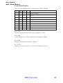
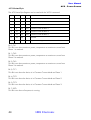
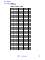
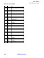
User Manual
ACS - Power Source
HBS Electronic GmbH
User Manual
ACS - Power Source
HBS Electronic GmbH
Mannheimer Strasse 89-91
68782 Bruehl
Tel. +49 (0) 6202 / 97 87 46-0
Fax +49 (0) 6202 / 97 87 46-6
email [email protected]
www.hbs-electronic.de
Copyright © HBS Electronic GmbH. All rights reserved. Changes without notice any time.
2
HBS Electronic
AM-1007-06.62-E
HBS Electronic
User Manual
ACS - Power Source
INTRODUCTION ...........................................................................6
FEATURES: .........................................................................................................6
SAFETY INSTRUCTIONS .................................................................7
EQUIPMENT DESCRIPTION............................................................9
FRONTPANEL.....................................................................................................9
Display ...................................................................................................................9
Load-Key................................................................................................................9
Functions-Keys .......................................................................................................9
Menu-Key...............................................................................................................9
Esc-Key ..................................................................................................................9
Enter-Key ...............................................................................................................9
Display-Key............................................................................................................9
More-Key................................................................................................................9
Measure-Keys .........................................................................................................9
Rotary Encoder .......................................................................................................9
Output-Connectors..................................................................................................9
Main Switch ...........................................................................................................9
REARPANEL ........................................................................................................9
Output Connector....................................................................................................9
GENERAL ....................................................................................10
DISPLAY ORGANIZATION.................................................................................10
Measured value line ..............................................................................................10
Statusline ..............................................................................................................10
Menuline ..............................................................................................................10
INPUT MODE ...................................................................................................10
Continual ..............................................................................................................10
Single ...................................................................................................................10
3-PHASE OPERATION..................................................................11
MENU..............................................................................................................11
MEASURE SELECT.............................................................................................11
MEASURE-CHANGE .........................................................................................11
FIRST STEPS.................................................................................12
VOLTAGE SETTING ..........................................................................................12
FREQUENCY SETTING .....................................................................................12
ENABLE LOAD / OUTPUT .................................................................................12
MANUAL OPERATION .................................................................13
MEASURE SELECT.............................................................................................13
MEASURE CHANGE ..........................................................................................13
INPUT MODE ...................................................................................................13
Continual ..............................................................................................................13
Single ...................................................................................................................13
CHANGE OF MODE ...........................................................................................13
LIMITS ..............................................................................................................13
ENABLE LIMIT...................................................................................................13
PRESETS ...........................................................................................................13
PRESET CALL.....................................................................................................14
CHANGE PRESET...............................................................................................14
UNIT STATES ...............................................................................15
SAVE STATE ......................................................................................................15
LOAD STATE......................................................................................................15
STATE POWER ON.............................................................................................15
CURRENT REGULATION ..............................................................16
CONSTANT CURRENT......................................................................................16
PEAK CURRENT ...........................................................................16
INRUSH CURRENT.............................................................................................16
PERIODIC PEAK CURRENT ..............................................................................16
CURRENT CUT OFF ...........................................................................................17
HBS Electronic
3
User Manual
ACS - Power Source
POWER DISABELING.........................................................................................17
PHASE .........................................................................................18
SWITCH ON PHASE............................................................................................18
EXTERNAL OSCILLATOR.................................................................................18
ENABLE EXTERNAL OSZILLATOR .................................................................18
BAUDRATE SELECT ..........................................................................................19
DISPLAY-BRIGHTNESS ..................................................................20
BRIGHTNESS CHANGE .....................................................................................20
SEQUENCES................................................................................20
SEQUENCE - LOAD - SAVE - RUN....................................................................20
SEQUENCE LOADING ......................................................................................21
SEQUENCE SAVING ........................................................................................21
SEQUENCE RUNNING ......................................................................................21
REMOTE CONTROL .....................................................................22
GENERAL.........................................................................................................22
RS232 INTERFACE ...........................................................................................22
IEEE488 INTERFACE.........................................................................................22
SETTINGS: ..........................................................................................................22
PROGRAMMING..........................................................................23
COMMAND SYNTAX.........................................................................................23
COMMAND INPUT .............................................................................................23
REMOTE-STATE.................................................................................................23
Local ...............................................................................................................23
Remote ............................................................................................................23
Remote with Lockout .......................................................................................23
PROGRAMMING EXAMPLES............................................................................24
SEQUENCE PROGRAMMING EXAMPLE .........................................................25
COMMON - COMMANDS ..................................................................................26
MEASURE - COMMANDS..................................................................................29
OUTPUT - COMMANDS .....................................................................................30
SEQUENCE - COMMANDS ................................................................................32
SOURCE - COMMANDS .....................................................................................34
SYSTEM - COMMANDS.....................................................................................37
COMMAND-TABLE............................................................................................38
SEQUENCE-COMMANDS ..................................................................................40
STATUS REGISTER ............................................................................................42
Status-Byte............................................................................................................42
Event-Status-Register ............................................................................................43
ACS-Status-Byte ...................................................................................................44
APPENDIX ....................................................................................45
IEEE488 ADRESS-TABLE....................................................................................45
IEEE488 ASSIGNMENT.....................................................................................46
RS232 ASSIGNMENT .......................................................................................47
POWER-OUT ASSIGNMENT.............................................................................47
MENU STRUCTURE ......................................................................48
MENU STRUCTURE - Option 3 Phases ...........................................49
STATE 0 - Default Settings .............................................................50
Specifications ...............................................................................51
Specifications ...............................................................................52
4
HBS Electronic
User Manual
ACS - Power Source
HBS Electronic
5
User Manual
ACS - Power Source
INTRODUCTION
Thank you for your decision for a product of HBS electronic GmbH.
The ACS Power Source is a programmable AC Source of high efficiency.
The µP controlled sine wave oscillator generates accurate and stable voltages and frequencies. The design of the power booster guarantees a safe feeding of the load.
This manual includes a description of the programmable ACS Power
Source with the specifications and operating instructions.
HBS-Electronic GmbH
FEATURES:
High Speed Mikroprozessor
Vacuum-Fluorescence Display
Manual operation on frontpanel
Remote control (Option) via RS232, USB, LAN or GPIB
AC and DC Mode
Constant current and constant voltage mode
V, I, IP, P, VA, PF, CF Measurement
Programable Limits für U, I, P
20 storable unit states
20 storable Sequenz-Tables (Option)
3-Phase-Mode (Option)
Protection against: over power, over voltage, over current and over temperature
Temperature controlled fan
6
HBS Electronic
User Manual
ACS - Power Source
SAFETY INSTRUCTIONS
Only qualified personnel are allowed to debug and to operate this equipment or to work close to this. Only when this product is transported and installed in a proper way and operated and maintained accordig to the recommendations, can it implement the functions properly and reliably.
The qualified personnel are specified as those personnel who carry out
commissioning, grounding and apply volume identification to the circuits,
equipments and systems according to the available safety practices and
standards.
Before switching on the equipment make sure, that the selected voltage is the same as environment power voltage!
Only connect the power cable with a 3 pole grounded plug to main
power!
To avoid damaging the equipment please be sure to change a suitable type of fuse!
Do not remove any covers or parts while equipment is working! There is a high risk of injuries touching life components!
WARNING!
The ACS Power Source can supply up to 1000 V at the ouput!
There is a high risk of life when touching the output connectors or
the connected probe during operation!
HBS Electronic
7
8
OutputConnector
~
+
~
-
HBS Electronic
Display-Key
ACS - Power Source
Function-Keys
Load
Enter
Esc
Menu
More
Display
Measure 4
Measure 3
More-Key
Coarse
Measure-Keys
Measure 2
Display
Measure 1
HBS Electronic GmbH
Output
Measure-Keys
Fine
Rotary Knobs
Main Switch
User Manual
ACS - Power Source
User Manual
ACS - Power Source
EQUIPMENT DESCRIPTION
FRONTPANEL
The drawing (pg 8) is showing the fronpanel with its elements.
These elements are: display, keys, rotary knobs, output connectors and main
switch.
Display
To display the input- and measured values there is a 4*20 chrs Vacuum Fluorescence Display used which is divided in:
menu line, status line and measure value table
Load-Key
Connects / disconnects output power to the load
Function-Keys
4 keys to select action
Menu-Key
Main menu change
Esc-Key
Return to main from submenu
Enter-Key
Input confirmation
Display-Key
Insertion of the satus line, when faded out
More-Key
Call auxiliary menus
Measure-Keys
Indicate value selection
Rotary Knobs
Changing of input values by turning
Output-Connectors
Connection of power output to the load
Main Switch
Switch ON / OFF the AC source
REARPANEL
Output Connector
Connection of power output to the load
Pins 1 and 6 (Power-Output).
Pins 2 und 5 (Sense) Voltage Measurment.
Pins 3 und 4 (S-Connector) must be shorten for Output-Relais ON.
Connector Pinout shown on end of Document.
HBS Electronic
9
User Manual
ACS - Power Source
GENERAL
DISPLAY ORGANIZATION
The display surface is partitioned into the ranges menu line, status line and
measured value table
Measuretable 1.-4.
1.
3.
DC=00.00V AC=220.0V
F=50.00Hz AC=05.20A
Power > P-Max
UAC UDC Irms Freq
Statusline
2.
4.
Menuline
Measured value line
Indication of measured and input values.
On Option „3 Phase“ the Table shows only Mesurments of the same kind.
for example:
Measure 1. - Measurment AC-Voltage Phase 1
Measure 2. - Measurment AC-Voltage Phase 2
Measure 3. - Measurment AC-Voltage Phase 3
Statusline
Indication of input values, error indication and instructions.
By indication of „I!“ at the right edge the source announces CC - mode
Menuline
Indicates menu choice.
INPUT MODE
The ACS Power Source supports two input variants.
Continual
Contnuous input with direct effect to the output of the source.
Single
Single input with confirmation by „ENTER KEY“ before effect to the output
10
HBS Electronic
User Manual
ACS - Power Source
3-PHASE OPERATION
MENU
The contents of UAC Menu are diplayed below on the screen:
Measure 1
Measure 3
Display
Esc
AC=220.0V AC=220.0V
AC=220.0V
AC=220.0V
UAC1 UAC2 UAC3 All
Menu
Measure 2
Measure 4
More
Enter
Load
Press the function key below >All<. The input value is shown in the status line.
Now you can adjust the required voltage for all phases by turning the rotary
knobs.
With the function key below the Word >UAC1< you can adjust the required
voltage for Phase 1 .
Key-actions:
Functionkey >UAC1< Voltage Phase 1
Functionkey >UAC2< Voltage Phase 2
Functionkey >UAC3< Voltage Phase 3
The Sub-Menu’s who where selectet by the >More< key effect only to the selectet phase.
For the description of this functions look in the correspending chapters.
Use the same procedure to Input DC-voltage, current, frequency and Phase.
See also Menu-Structure.
MEASURE SELECT
The ACS - Power Source shows 3 measurements in the Display .
On Option „3 Phases“ this table shows any time measurements of the same
kind.
for example:
Measure 1. - measured value AC-voltage Phase 1
Measure 2. - measured value AC-voltage Phase 2
Measure 3. - measured value AC-voltage Phase 3
This Measurements are selectet with the >Measure< keys.
MEASURE-CHANGE
Press >Measure 1<, >Measure 2<, >Measure 3< or >Measure 4< beside the Display. Each pressing of the key effects the change of the displayed
measurement.
One measurement after each other for F, V, C, VA, P, PF, CrF, CP is displayed.
HBS Electronic
11
User Manual
ACS - Power Source
FIRST STEPS
VOLTAGE SETTING
After turn on the contents below are diplayed on the screen:
Measure 1
Measure 3
Display
Esc
DC=00.00V AC=220.0V
F=50.00Hz AC=00.00A
AC=220.0V
UAC UDC
Irms Freq
Menu
Measure 2
Measure 4
More
Enter
Load
Press the function key below >UAC<. The input value is shown in the status line.
Adjust required voltage by turning the rotary knobs. If the value is not visible (after 5 sec.) it can be faded in by pressing the >DISPLAY< key or turning the
rotary knob.
After this you can change voltage freely again.
FREQUENCY SETTING
After turn on the contents below are diplayed on the screen:
Measure 1
Measure 3
Display
Esc
DC=00.00V AC=220.0V
F=50.00Hz AC=00.00A
F=050.0Hz
UAC UDC
Irms Freq
Menu
Measure 2
Measure 4
More
Enter
Load
Press the function key below >Freq<. The input value is shown in the status line.
Adjust required frequency by turning the rotary knobs. If the value is not visible
(after 5 sec.) it can be faded in by pressing the >DISPLAY< key or turning the
rotary knob.
After this you can change frequency freely again.
ENABLE LOAD / OUTPUT
By pressing the >Load< key the output power will be connected to the load.
The >Load< key shines green.
Press >Load< key again to disable.
12
HBS Electronic
User Manual
ACS - Power Source
MANUAL OPERATION
MEASURE SELECT
The ACS Power Source display 4 measures on the screen. These can be selected by pressing the >Measure< keys.
MEASURE CHANGE
Press the >Measure 2< key on the top right beside the Display. Each pressing
of the key effects the change of displayed measured value right on the top of
the display.
One value after each other for F, V, C, VA, P, PF, CrF, CP is displayed.
INPUT MODE
The ACS Power Source supports two input variants.
Continual
Contnuous input with direct effect to the output of the source.
Single
Single input with confirmation by „ENTER KEY“ before effect to the output.
CHANGE OF MODE
Return to main menu by pressing >Menu< key as to do under “preset call”.
Press the key >More< , then the >function< key below displayed >UAC<.
The content of the screen changes (see preset call). The input value is displayed
in the satus line.
Press >function< key below the word >cont<. The mode changes from
continual to the single mode, the string >sing< is displayed now and vice versa.
LIMITS
To protect the probes from e.g. high voltage, the input value can be limited, i.e.
the voltage can only be adjusted to a defined value.
ENABLE LIMIT
Change to main menue by pressing >Menue< key.
DC=00.00V AC=220.0V
F=50.00Hz AC=05.20A
AC=220.0V
Pre1 Mem Cont LiOff
Press the key >More< , then the >function< key below displayed >UAC<.
The content of the screen changes as descibed above, the input value is displayed in the satus line.
Adjust now required voltage by turning the rotary knobs.
Press >function< key below >LiOff<. The current AC voltage value will be
accepted as input limit, display changes to >LiOn<. Vice versa.
HBS Electronic
13
User Manual
ACS - Power Source
PRESETS
The ACS Power Source can save often used input characteres as “preset”.
PRESET CALL
Change to this main menue by pressing >Menu< key.
Measure 1
Measure 3
Display
Esc
DC=00.00V AC=220.0V
F=50.00Hz AC=05.20A
UAC
UDC
Irms Freq
Menu
Measure 2
Measure 4
More
Enter
Load
Press the key >More< , then the >function< key below displayed >UAC<.
The content of the screen changes as descibed as following, the input value is
displayed in the status line.
Measure 1
Measure 3
Display
Esc
DC=00.00V AC=220.0V
F=50.00Hz AC=05.20A
AC=220.0V
Pre1 Mem Cont LiOff
Menu
Measure 2
Measure 4
More
Enter
Load
Press the >function< key below >Pre1<. The value of „preset 1“ is recalled
the screen chractere changes to >Pre2<. Pressing the key again, „preset 2“ is
recalled etc.
CHANGE PRESET
Change to main menu by pressing >Menu< as described under “preset call”.
Press the key >More< , then the >function< key below displayed >UAC<.
The content of the screen changes (see preset call). The input value is displayed
in the satus line.
Press >function< key below >Pre1< until required „preset No.” is displayed. Adjust now required voltage by turning the rotary knobs.
Then press the >function< key below >Mem< , the new value for this preset is saved.
If you are saving now an „unit state“, the saved presets are available even after
switch OFF the unit and can be recalled at switch ON the ACS Power Source
again.
14
HBS Electronic
User Manual
ACS - Power Source
UNIT STATES
The ACS-Power Source can save 20 complete unit states(state 1 to 20) for later
use. The state No. 0 contains the manufacturer parameters and cannot be
changed. A list of stored parameters is attached as appendix.
To load and save states change to this menu by pressing the >Menu< key.
Measure 1
Measure 3
Display
Esc
DC=00.00V AC=220.0V
F=50.00Hz AC=05.20A
SAV-Nr.01
Pwr Seq Stat Opt.
Menu
Measure 2
Measure 4
More
Enter
Load
Reach the state menue by pressing the >function< key below >Stat<
Measure 1
Measure 3
Display
Esc
DC=00.00V AC=220.0V
F=50.00Hz AC=05.20A
SAV-Nr.01
Rcl Save P-On
Menu
Measure 2
Measure 4
More
Enter
Load
SAVE STATE
To save a set of settings in state No. (n) press the >function< key below
>Save<. The input value is displayed in the status line.
Select now the required state number by turning the rotary knobs.
Press >Enter< to save the state.
LOAD STATE
WARNING!
Recalling of a saved „unit state“ may effect high voltages at the
output!
To load the settings from state number (n) press >function< key below
>Rcl<. The input value is displayed in the satus line.
Select now the required state number by turning the rotary knobs.
By pressing the >Enter< key, the state is loading.
STATE POWER ON
You can operate the states 0 to 20 as switch on setting of the ACS Power Source.
To load a setting from state number (n) at the next switch on press the
>function< key below >P-On<. The input value is displayed in the satus line.
Select now the required state number by turning the rotary knobs. By pressing
the >Enter< key the number of the „Power On State“ is saved.
HBS Electronic
15
User Manual
ACS - Power Source
CURRENT REGULATION
CONSTANT CURRENT
Change to this main menue by pressing >Menu< key.
Measure 1
Measure 3
Display
Esc
DC=00.00V AC=220.0V
F=50.00Hz AC=00.00A
AC=220.0V
UAC UDC
Irms Freq
Menu
Measure 2
Measure 4
More
Enter
Load
Press the >function< key below >Irms< The input value is displayed in the
status line.
Select now the required voltage by turning the rotary knobs. The source indicates an active current regulation by displaying „I!“ at the right edge of the status
line.
PEAK CURRENT
With the ACS Powe Source you can take a measurement of the peak current,
the periodic and the inrush current as well.
INRUSH CURRENT
Select the required parameters for voltage, current frequency etc.
Set one measurement indication to peak current >IP<.
See measure select.
Go by pressing >More< and >Irms< keys to the extended current menu.
Reach the second level of the extended current menu by pressing the >Menu<
key.
Measure 1
Measure 3
Display
Esc
DC=00.00V IP=000.0A
F=50.00Hz AC=05.20A
SAV-Nr.01
Max Time Pclr
Menu
Measure 2
Measure 4
More
Enter
Load
To clear the peak current memory by pressing the >function< key below
>PClr<.
Enable the load with >Load< key. The inrush current IP=X.XXXA is now displayed.
PERIODIC PEAK CURRENT
Do the same preparation as described under „Inrush current“.
Clear the peak current memory by pressing >function< key below >PClr<
at enabled load.
The peak current IP=X.XXXA is displayed now
16
HBS Electronic
User Manual
ACS - Power Source
CURRENT CUT OFF
The ACS Power Source can disable the load automatically exceeding the preset
current limit, the exceeding time can be programmed.
Until the cutoff time is reached higher Current-Values can appear, cause this
function is no current regulation.
Go by pressing >More< and >Irms< keys to the extended current menu.
Reach the second level of the extended current menu by pressing the >Menu<
key.
Measure 1
Measure 3
Display
Esc
DC=00.00V AC=220.0V
F=50.00Hz AC=05.20A
SAV-Nr.01
Max Time PClr
Menu
Measure 2
Measure 4
More
Enter
Load
Press the >function< key below >Max< to define the current limit. Select
the required parameter for the current and confirm with >Enter< key.
Press the >function< key below >Time< to define the time. Select the required parameter for the time and confirm with >Enter< key.
POWER DISABELING
The ACS Power Source can disable the load automatically exceeding the preset
power limit.
Change to this main menue by pressing >Menu< key.
Measure 1
Measure 3
Display
Esc
AC=00.00V IP=000.0A
F=50.00Hz AC=05.20A
Pwr
Stat Opt.
Menu
Measure 2
Measure 4
More
Enter
Load
Press the >function< key below >Pwr< to define the power limit. Select the
required parameter for the power and confirm with >Enter< key.
HBS Electronic
17
User Manual
ACS - Power Source
PHASE
The ACS Power Source can switch on required voltage at a defined phase angle.
SWITCH ON PHASE
Select the required parameter for voltage, current frequency etc.
Go to the main menu phase by pressing the >Menü< key.
Measure 1
Measure 3
Display
Esc
AC=00.00V IP=000.0A
F=50.00Hz AC=05.20A
Pha1
P.On
Menu
Measure 2
Measure 4
More
Enter
Load
Press the >function< key below >P.On< The letters change to >P.Off<.
Press the >function< key below >Pha1<
Select the required parameter for the phase angle.
Enable load by ressing >Load< key. The load is enabeled, the AC voltage is
at 000.0V.
Press the >function< key below >P.Off< The letters change to >P.On<
and the AC voltage is connected with selected phase angle.
EXTERNAL OSCILLATOR
The ACS Power Source can be fed with an external signal. The Power Source
works as a real power amplifier in this mode.
Take care on the maximum permissible frequency on this Input!
Standard maximum 500 Hz
Option F1 maximum 1 KHz
Option F2 maximum 2 KHz
ENABLE EXTERNAL OSZILLATOR
Go to the main menu phase by pressing the >Menü< key.
Measure 1
Measure 3
Display
Esc
AC=00.00V IP=000.0A
F=50.00Hz AC=05.20A
Pwr
Seq
Stat Opt.
Menu
Measure 2
Measure 4
More
Enter
Load
Press the >function< key below >Opt.< to enter the option menu.
18
HBS Electronic
User Manual
ACS - Power Source
Measure 1
Measure 3
Display
Esc
AC=00.00V IP=000.0A
F=50.00Hz AC=05.20A
ExOf
Baud Brigh
Menu
Measure 2
Measure 4
More
Enter
Load
Press the >function< key below >Ex.Of< The letters change to >Ex.On<
and the signal is fed by the external input.
Pressing the key again activates the internal signal of the ACS Power Source.
BAUDRATE
With the ACS Power Power Source you have the choice to select the transfer rate of the RS 232 interface between 9600 and19200 Baud.
BAUDRATE SELECT
Change to this main menue by pressing >Menu< key.
Measure 1
Measure 3
Display
Esc
AC=00.00V IP=000.0A
F=50.00Hz AC=05.20A
Pwr
Seq
Stat Opt.
Menu
Measure 2
Measure 4
More
Enter
Load
Press the >function< key below >Opt.< to enter the option menu.
Measure 1
Measure 3
Display
Esc
AC=00.00V IP=000.0A
F=50.00Hz AC=05.20A
ExOf
Baud Brigh
Menu
Measure 2
Measure 4
More
Enter
Load
Press the >function< key below >Baud<.
Select the required Baudrate for the RS232 Interface by turning the rotary
knobs.
This setting takes effect after the next restart.
HBS Electronic
19
User Manual
ACS - Power Source
DISPLAY-BRIGHTNESS
The brightness of the vacuum fluorescence display of the ACS Power Source
can be adjusted in 4 levels.
BRIGHTNESS CHANGE
Change to this main menue by pressing >Menu< key.
Measure 1
Measure 3
Display
Esc
AC=00.00V IP=000.0A
F=50.00Hz AC=05.20A
Pwr
Seq
Stat Opt.
Menu
Measure 2
Measure 4
More
Enter
Load
Press the >function< key below >Opt.< to enter the option menu.
Measure 1
Measure 3
Display
Esc
AC=00.00V IP=000.0A
F=50.00Hz AC=05.20A
ExOf
Baud Brigh
Menu
Measure 2
Measure 4
More
Enter
Load
Press the >function< key below >Brigh<.
Select the required brightness level by turning the rotary knobs.
SEQUENCES
The ACS Power Source provides operation of automatic command sets (sequences).
The operator can save 20 sequences of 50 commands for later recall. This possibility allows e.g. simultions of voltage surges and drops.
The minimum time for a command is 10 msec at a step length of also 10 msec.
The complete data transfer of sequences can be made by the help of the software tool “ACS CONTROL” or by simple remote commands.
SEQUENCE - LOAD - SAVE - RUN
Change to this main menue by pressing >Menu< key.
Measure 1
Measure 3
Display
Esc
AC=00.00V IP=000.0A
F=50.00Hz AC=05.20A
Pwr
Seq
Stat Opt.
Menu
Measure 2
Measure 4
More
Enter
Load
Press the >function< key below >Seq.< to enter the sequence menu.
20
HBS Electronic
User Manual
ACS - Power Source
Measure 1
Measure 3
Display
Esc
AC=00.00V IP=000.0A
F=50.00Hz AC=05.20A
Go
Stop Rcl
Menu
Save
Measure 2
Measure 4
More
Enter
Load
SEQUENCE LOADING
To load a sequence Number (n) from memory(NV-RAM) in the execution-memory(RAM) press the function key below the word >Rcl<. The input value is
displayed in the status line.
Select now the required memory number by turning the rotary knobs.
By pressing the >Enter< key the sequence is loaded into the execution-memory(RAM).
SEQUENCE SAVING
To save a previous with the PC-programm(ACS-Control) or remote-commands
transfered sequence Number (n) from execution-memory(RAM) in the memory(NV-RAM) press the function key below the word >Save<. The input value is
displayed in the status line.
Select now the required memory number by turning the rotary knobs.
By pressing the >Enter< key the sequence is saved in the memory(NV-RAM).
SEQUENCE RUNNING
To run a previous in execution-memory(RAM) loaded sequence press the function key below the word >Go<. The input value is displayed in the status line.
Select now the required number of sequence-repetitions by turning the rotary
knobs.
Run the sequence by pressing >Enter< key.
The sequence running can be interrupted or stopped by pushing the function
key below >Stop<.
HBS Electronic
21
User Manual
ACS - Power Source
REMOTE CONTROL
GENERAL
The ACS Power Source can be controlled via an interface RS 232 or via IEEE
488 as an option. All settings and measuerements can be done with these interfaces, the resolution is 12 Bit.
RS232 INTERFACE
The data transfer rate of the RS 232 interface is 19200 or 9600 Baud, 8 Databits, no parity, 1 Stopbit
The connection to the control PC is made by a „Null ú Modem“ assignment, the
signals RXD, TXD, RTS und CTS were used.
Tu enable the RS 232 interface all the DIP switches of the optional interfaces
have be locked in RS 232 mode.
IEEE488 INTERFACE
The IEEE 488 interface was realized with the GPIB Controller CB 7210.2 (Computer Boards). It provides an IEEE 488.2 conformal interface.
SETTINGS:
The settings of the interface operation parameters were made by the 8-way DIP
switch on the rear of the Power Source. The DIP switch is only read out at
Power-On. Due to this a restart of the ACS Power Source is necessary having
changed the settings of the DIP switch.
Switch Nr.
1. IEEE488 Adresse Value 1
2. IEEE488 Adresse Value 2
3. IEEE488 Adresse Value 4
4. IEEE488 Adresse Value 8
5. IEEE488 Adresse Value 16
6. RS232 / IEEE488
7. not used
8. 19200 Baud / 9600 Baud
Switch 6.
=OFF RS232 operation
=ON IEEE488 operation
At IEEE 488 operation the BAUDRATE must be set on DIP switch and the frontpanel at 19200 Baud!
Switch 8.
=OFF 19200 Baud
=ON 9600 Baud
*IEEE488
Switch 1 to switch 5 specifie the IEEE unit addressThe address area is between 1
and 30, the setting of the address is mede binary by the assigned value.
To get address 5 lock switch 1 and switch 3 at ON.
Switch 1.
+ Switch 3.
=1
=4
=5
Refer the attached address table (appendix)
22
HBS Electronic
User Manual
ACS - Power Source
PROGRAMMING
Commands and feedbacks are transmitted as ASCI codes. Before a new command can be sent, the feedback must be read out completely.
COMMAND SYNTAX
A command consists of keyword, delimiter, value and end character. Commands can also consist of several keywords, these have to be separated by colon <:>.
The keyword represents the name of the command for identifying.
As delimiter between command and value a comma <,> is agreed.
The end character terminates the command. RS232 mode allows <CR> or
<LF> as end character; IEEE488 mode recognizes <LF> or the BUS message
<EOI> as end character.
If unit is sending signals to the BUS (Talker) these will be terminated with <LF>
and <EOI> simultanuously.
COMMAND INPUT
Keyword input in capitals, lower cases or in mixed way is allowed.
-e.g. command.:
sour:voltac,220
SOUR:VOLTAC,220
Sour:VoltAc,220
At the input of values numbers can be sent as “integer” or “real” separated by
<.> as a comma.
-e.g. INTEGER:
SOUR:VOLTAC,1
SOUR:VOLTAC,10
-e.g. REAL :
SOUR:VOLTAC,220.0
SOUR:VOLTAC,200.
SOUR:VOLTAC,0.4
SOUR:VOLTAC,.3
SOUR:VOLTAC,230.100
REMOTE-STATE
The ACS-Power Source supports 3 modes of remote control
Local
Unit can be operated manually or remote controlled
Remote
Unit can be remote controlled. Operation by hand is possible after pressing
>Menu< key, which is workig as <Local> key in this case.
Remote with Lockout
Unit can only be remote controlled in this mode. An operation by hand is only
possible after having sent the command „Local“ or after restart the ACS-Power
Source.
HBS Electronic
23
User Manual
ACS - Power Source
PROGRAMMING EXAMPLES
*idn?
*rcl,0
SOUR:VOLTAC,230
OUTP,1
gtl
Unit returns the ID-string.
This first command shifts the unit to Remote State at
IEEE 488 mode. At RS232 mode the command
<SYST:REM> shifts the unit to Remote-State.
reads out default data from register 0.
adjusts the AC voltage to 230V AC.
enables the output relay.
IEEE488 command: back to Local-State.
At RS232 mode the command <SYST:LOC> shifts
the unit to Local-State.
Setting an AC voltage 115VAC / 60Hz at a max. current of 0.5A.
SOUR:VOLTAC,115
SOUR:CURR,0.5
SOUR:FREQ,60
OUTP,1
voltage 115V-AC
current 0.5A
frequency 60Hz
output relay ON
Setting a DC voltage 24VDC at a max. current of 1A.
SOUR:VOLTDC,24
SOUR:CURR,1
OUTP,1
voltage 24V-DC
current 1A
output relay ON
Setting an AC voltage 230VAC / 50Hz, the voltage should be connected at a
phase angle of 90 degs.
SOUR:VOLTAC,230
SOUR:FREQ,50
OUTP:PHASON,0
SOUR:PHAS,90
OUTP,1
OUTP:PHASON,1
voltage 230V-AC
frequency 50Hz
phase(voltage) OFF
phase angle 90 degree
output relay ON
phase(voltage) turns on
at 90 degree
3-Phase mode:
Setting an AC voltage 115V AC/60Hz and 160V AC/60Hz at phase 1.
SOUR:FREQ,60
SOUR:VOLTAC,115
SOUR1:VOLTAC,160
OUTP,1
24
frequency 60Hz
voltage 115V-AC (all phases)
voltage 160V-AC (phase 1)
output relay ON
HBS Electronic
User Manual
ACS - Power Source
SEQUENCE PROGRAMMING EXAMPLE
Generate a sequence with 10ms/100VAC, 10ms/130VAC, 20ms/100VAC by repetition of 2 times.
The sequence-commands are entered as decimal values.
SEQ:TIME,00.00.00.010
SEQ:VAL1,100
SEQ:VAL2,0
SEQ:VAL3,500
SEQ:NEW,4
command-duration 10 ms
command-value 1 (voltage 100V on UAC-command)
command-value 2 (unused on UAC-command)
command-value 3 (frequency 500 HZ-UAC-command)
sequence-command UAC, transfer to sequence-table
SEQ:NEW only on new-table
SEQ:TIME,00.00.00.010
SEQ:VAL1,130
SEQ:VAL2,0
SEQ:VAL3,500
SEQ:SET,4
command-duration 10 ms
command-value 1 (voltage 130V on UAC-command)
command-value 2 (unused on UAC-command)
command-value 3 (frequency 500 HZ-UAC-command)
sequence-command UAC, tranfer to sequence-table
SEQ:SET for more table-entrys
SEQ:TIME,00.00.00.020
SEQ:VAL1,100
SEQ:VAL2,0
SEQ:VAL3,500
SEQ:SET,4
command-duration 20 ms
command-value 1 (voltage 100V on UAC-command)
command-value 2 (unused on UAC-command)
command-value 3 (frequency 500 HZ-UAC-command)
sequence-command UAC, transer to sequence-table
SEQ:SET for more table-entrys
SEQ:TIME,00.00.00.010
SEQ:VAL1,100
SEQ:VAL2,0
SEQ:VAL3,500
SEQ:SET,255
command-duration 10 ms
command-value 1 (voltage 100V on UAC-command)
command-value 2 (unused on UAC-command)
command-value 3 (frequency 500 HZ-UAC-command)
sequence-command END, transfer to sequence-table
SEQ:SET for more table-entrys
SEQ:CNT,2
command - number of repetition for the sequence
SEQ:STORE,1
store the sequence in memory No.1
SEQ:GO,2
Starts the sequence with 2 repetitions.
10ms
cmd 1
10ms
cmd 2
20ms
cmd 3
10ms
cmd 1
Sequence
repetition 1
HBS Electronic
10ms
cmd 2
20ms
cmd 3
Sequence
repetition 2
25
User Manual
ACS - Power Source
COMMON - COMMANDS
*ACS?
*ACSB?
*CLS
*ESE
*ESE?
*ESR?
*IDN?
*OPC
*OPC?
*OPT?
*RCL
*RST
*SAV
*SRE
*SRE?
*STB?
returns the actual ACS-Status-Byte.
returns the ACS-Status-Byte.
delete the Status-Byte and Event-Status-Register
sets the Event-Status-Enable-Register.
returns the Event-Status-Enable-Register.
returns the Event-Status-Register.
returns the ID-String.
sets the OperationComplete Bit in the ESR-Register.
write an ASCII ”1” in the Out-Buffer.
returns the ID of the installed options.
recalls for unit state X.
recalls for unit default settings.
saves unit state X.
sets the Service-Request-Enable-Register.
returns the Service-Request-Enable-Register.
returns the Status-Byte-Register.
*ACS?
Returns the actual ACS-Status-Register.
Response: 0 - 255
Bitdefinition - see in Chapter Status-Register.
*ACSB?
Returns the ACS-Status-Register.
This Register stores the data until readout and delete after that.
Response: 0 - 255
Bitdefinition - see in Chapter Status-Register.
*CLS
Delete the Status-Byte and Event-Status-Register
Enable Registers are not delete.
*ESE,X
Sets Bits in Event-Status-Enable-Register. This Register is an Enable-Mask
for the Event-Status-Register.
X= 0 - 255
Bitdefinition - see in Chapter Status-Register.
*ESE?
Returns the Event-Status-Enable-Register.
Response: 0 - 255
Bitdefinition - see in Chapter Status-Register.
*ESR?
Returns the Event-Status-Register.
Response: 0 - 255
Bitdefinition - see in Chapter Status-Register.
26
HBS Electronic
User Manual
ACS - Power Source
*IDN?
returns the Unit ID-String.
Response:
Manufacturer: HBS Electronic,
Unit-Typ:
ACS-0250-PS,
Serien No.
0,
Revision:
V1.21
*OPC
sets the Operation-Complete Bit in the ESR-Register.
Bitdefinition - see in Chapter Status-Register.
*OPC?
write an ASCII ”1” in the Out-Buffer.
Response: 1
*OPT?
Returns the ID of the installed options.
Response: HV,F1
if options HV and F1 are installed.
possible options:
NONE no Option
HV:
expanded voltage-range 1
XHV: expanded voltage-range 2
F1:
expanded frequency-range 1
F2:
expanded frequency-range 2
SEQ: sequenz Option
CR2: current-measurement-range 2
OT1: output-option 1
3P:
3 phase option
*RST
recalling for Unit default settings.
See appendix STATE 0 - Default Settings.
*RCL,X
WARNING! Recalling of a saved „unit state“ may effect high voltages
at the output!
Recall unit state X.
X= 0 - 20
*SAV,X
Save unit state X.
X= 1 - 20
HBS Electronic
27
User Manual
ACS - Power Source
*SRE,X
Sets Bits in the Event-Status-Enable-Register. This Register is an EnableMask for the Event-Status-Register.
X= 0 - 255
Bitdefinition - see in Chapter Status-Register.
*SRE?
Returns the Event-Status-Enable-Register.
Response: 0 - 255
Bitdefinition - see in Chapter Status-Register.
*STB?
Returns the Event-Status-Register.
Response: 0 - 255
Bitdefinition - see in Chapter Status-Register.
28
HBS Electronic
User Manual
ACS - Power Source
MEASURE - COMMANDS
MEAS[n]
n = 1, 2 or 3 for Phases 1, 2 oder 3
Standard (e.g. MEAS:VOLT? for 1-Phase-source)
n = 0 is not available
:CURR?
:CURRP?
:CFACT?
:PFACT?
:VA?
:VOLT?
:POW?
Returns at the output measured current rms.
Returns at the output measured peak current.
Returns at the output measured crest factor.
Returns at the output measured power factor.
Returns at the output measured power(VA).
Returns at the output measured voltage rms.
Returns at the output measured power(W).
:CURR?
Returns at the output measured current rms.
Respose: C (A).
:CURRP?
Returns at the output measured peak current.
Response: C (A).
:CFACT?
Returns at the output measured crest factor.
Response: Factor N.
:PFACT?
Returns at the output measured power factor.
Response: Factor N.
:POW?
Returns at the output measured power.
Response: P (W).
:VOLT?
Returns at the output measured voltage rms.
Response: V (V).
:VA?
Returns at the output measured power.
Response: P (VA).
HBS Electronic
29
User Manual
ACS - Power Source
OUTPUT - COMMANDS
OUTP
:AUX
:AUX?
:OT1
:OT1?
:PHASON
:PHASON?
:PON
:PON?
:STAT
:STAT?
1* Option
sets the external oscillator to ON or OFF.
returns the state of the external oscillator
1* sets Output-Option 1
1* returns the State of the Output-Option 1
sets the phase (voltage).
returns the state of the phase (voltage).
sets the Power-On-State.
returns the preset value of the Power-ON-State.
sets the output relay to open or closed.
returns the state of the output relay.
:AUX,X
sets the external Oscillator.
X=1 extern Oscillator ON
X=0 extern Oscillator OFF
Take care on the maximum permissible frequency on this
Input!
Standard
Option F1
Option F2
maximum 500 Hz
maximum 1 KHz
maximum 2 KHz
:OT1,X
activate Output-Option 1.
X=1 Output-Option 1 ON
X=0 Output-Option 1 OFF
:PHASON,X
sets the Phase(voltage).
X=1 Phase(voltage) ON.
X=0 Phase(voltage) OFF.
:STAT,X
sets the Output-Relay.
X=1 Relay ON
X=0 Relay OFF
example: OUTP,1
OUTP:STAT,1
:AUX?
returns the state of the external oscillator.
Response: 0 | 1
1 extern Oscillator ON
0 extern Oscillator OFF
30
HBS Electronic
User Manual
ACS - Power Source
:OT1?
returns the State of the Output-Option 1.
Response: 0 | 1
1 Output-Option 1 ON
0 Output-Option 1 OFF
:PHASON?
returns the State the Phase(voltage).
Response: 0 | 1
X=1 Phase(voltage) ON.
X=0 Phase(voltage) OFF.
:PON,X
sets the Power-On-State (memory No.).
X=0 - 20
:PON?
Return the preset value of the Power-ON-State.
Response: Power-On-State No.
:STAT?
returns the State of the output-relay.
Response: 0 | 1
1 - Output-Relay enabled.
0 - Output-Relay disabled.
HBS Electronic
31
User Manual
ACS - Power Source
SEQUENCE - COMMANDS
SEQ
:CNT
:GO
:LOAD
:NEW
:SET
:STOP
:STORE
:TIME
:VAL1
:VAL2
:VAL3
sets the number of repetition for the sequence
starts the execution of a sequence
loads a sequence from NV-RAM into RAM
transfers the sequence data in the sequence-table
transfers the Sequenz data in the sequence-table
stops the execution of a sequence
store a sequence from RAM into NV-RAM
sets the time of the sequence-command
sets the value 1 for the sequence-command
sets the value 2 for the sequence-command
sets the value 3 for the sequence-command
:CNT,X
sets the number of repetition for the sequence.
X = number of repetition 0 - 60000
X = 0 forever
:GO,X
Starts the sequence with X repetition.
X = number of repetition 0 - 60000
X = 0 forever
without paramater = stored number of repetition
:LOAD,X
load a sequence from NV-RAM into RAM
X = sequence-number 1 - 20
:NEW,X
transfer the sequence data in the sequence-table.
use only for 1. table entry from a sequence !
the data of VAL1, VAL2, VAL3, TIME and CNT are transferd to the sequence-table.
X = sequence-command 1 - 255
command UAC =dec. 4
command-table see „sequence commands“
:SET,X
transfer the sequence data in the sequence-table.
the data of VAL1, VAL2, VAL3, TIME and CNT are transferd to the sequence-table.
X = sequence-command 1 - 255
command UAC =dec. 4
command-table see „sequence commands“
:STOP
32
HBS Electronic
User Manual
ACS - Power Source
stops the execution of a sequence
:STORE,X
store a sequence from RAM into NV-RAM
X = sequence-Number 1 - 20
:TIME,X
sets the time(command-duration) of the sequence-command
X in HH.MM.SS.MSMSMS minimal 10 ms in steps of 10 ms
SEQ:TIME,00.00.00.010
command-duration 10 ms
:VAL1,X
sets the value 1 for the sequence-command.
X in the unit of the sequence-command-data.
z.B. command UAC(dec. 4)
SEQ:VAL1,100
AC-Voltage 100 Volts
:VAL2,X
sets the value 2 for the sequence-command.
X in the unit of the sequence-command-data.
z.B. command UAC(dec. 4)
SEQ:VAL2,100
unused by UAC-command
:VAL3,X
sets the value 3 for the sequence-command.
X in the unit of the sequence-command-data.
z.B. command UAC(dec. 4)
SEQ:VAL3,50
Frequency 50 Hertz
HBS Electronic
33
User Manual
ACS - Power Source
SOURCE - COMMANDS
SOUR[n]
n = 1, 2 or 3 for Phase 1, 2 or 3
Standard (e.g. SOUR:VOLTAC,100) for 1-Phase-Source and
to set all 3 Phases at one time.
n = 0 is not available
:CURR
:CURRCLR
:CURRMAX
:CURRTIME
:CURRRNG
:FREQ
:PHAS
:POWMAX
:VOLTAC
:VOLTDC
:CURR?
:CURRMAX?
:CURRTIME?
:CURRRNG?
:FREQ?
:PHAS?
1* sets the current for constant current mode (CC).
clears the Peak-current memory(IP-Measure)
sets the current limit setpoint.
sets the time delay for current cut off.
*2 activate the current-measure-range 2
1* sets the frequency of the AC voltage
1* sets the phase of the voltage
sets the value for power cut off.
1* sets the value of the AC voltage
1* sets the value of the DC voltage
1* returns the preset value for constant current mode (CC).
returns the preset value for current cut off.
returns the preset value for the time delay for current cut off.
*2 returns the State of the current-measure-range 2
1* returns the preset value of the frequency of the AC vol
tage.
1* returns the preset value of the power on phase of the AC
voltage.
returns the preset value for power cut off.
1* returns the preset value for AC voltage
1* returns the preset value for DC voltage
:POWMAX?
:VOLTAC?
:VOLTDC?
*1 3-Phase-command (e.g. SOUR1:VOLTAC,100)
*2 Option
:CURR,X
sets the current for current constant mode (CC).
X in Ampere.
:CURRCLR
clears the Peak-Current memory(IP-Measure)
:CURRMAX,X
sets the point for current cut off.
X in Ampere.
:CURRTIME,X
sets the time delay for current cut off.
X in Seconds.
:CURRRNG,X
activate the current-measure-range 2.
X=1 current-Measure-range 2 ON
X=0 current-Measure-range 2 OFF
34
HBS Electronic
User Manual
ACS - Power Source
:FREQ,X
sets the frequency of the AC voltage
X in Hertz.
:PHAS,X
sets the phase of the voltage
X in Grad.
:POWMAX,X
sets the point for power cut off.
X in VA.
:VOLTAC,X
sets the value of the AC voltage
X in Volt.
:VOLTDC,X
sets the value of the DC voltage
X in Volt.
:CURR?
returns the preset value for constant current mode (CC).
Response: I in Ampere.
:CURRMAX?
returns the preset value for current cut off.
Response: I in Ampere.
:CURRTIME?
returns the preset value for the time delay for current cut off.
Response: T in seconds.
:CURRRNG?
returns the State of the current-measure-range 2.
Response: 0 | 1
1 current-measure-range 2 ON
0 current-measure-range 2 OFF
:FREQ?
returns the preset value of the frequency of the AC voltage
Response: F in Hertz.
:PHAS?
returns the preset value of the power on phase of the AC voltage
Response: Phase angle in degree.
HBS Electronic
35
User Manual
ACS - Power Source
:POWMAX?
returns the preset value for power cut off.
Response: P in VA.
:VOLTAC?
returns the preset value for AC voltage
Response: U in Volt.
:VOLTDC?
returns the preset value for DC voltage
Response: U in Volt.
36
HBS Electronic
User Manual
ACS - Power Source
SYSTEM - COMMANDS
SYST
:LOC
:REM
:RWL
shifts unit to Local-State
shifts unit to Remote-State
shifts unit to Local-Lockout-State
:LOC
shifts unit to Local-State
(only in RS232 Mode).
:REM
shifts unit to Remote-State
(only in RS232 Mode).
:RWL
shifts unit to Local-Lockout-State
(only in RS232 Mode).
HBS Electronic
37
User Manual
ACS - Power Source
COMMAND-TABLE
*ACS?
*ACSB?
*CLS
*ESE
*ESE?
*ESR?
*IDN?
*OPC
*OPC?
*OPT?
*RCL
*RST
*SAV
*SRE
*SRE?
*STB?
MEAS[n]
:CURR?
:CURRP?
:CFACT?
:PFACT?
:VA?
:VOLT?
:POW?
OUTP
:AUX
:AUX?
:OT1
:OT1?
:PHASON
:PHASON?
:PON
:PON?
:STAT
:STAT?
returns the actual ACS-Status-Byte.
returns the ACS-Status-Byte.
delete the Status-Byte and Event-Status-Register
sets the Event-Status-Enable-Register.
returns the Event-Status-Enable-Register.
returns the Event-Status-Register.
returns the ID-String.
sets the OperationComplete Bit in the ESR-Register.
write an ASCII ”1” in the Out-Buffer.
returns the ID of the installed options.
recalls for unit state X.
recalls for unit default settings.
saves unit state X.
sets the Service-Request-Enable-Register.
returns the Service-Request-Enable-Register.
returns the Status-Byte-Register.
Returns at the output measured current rms.
Returns at the output measured peak current.
Returns at the output measured crest factor.
Returns at the output measured power factor.
Returns at the output measured power(VA).
Returns at the output measured voltage rms.
Returns at the output measured power(W).
sets the external oscillator to ON or OFF.
returns the state of the external oscillator
1* sets Output-Option 1
1* returns the State of the Output-Option 1
sets the phase (voltage).
returns the state of the phase (voltage).
sets the Power-On-State.
returns the preset value of the Power-ON-State.
sets the output relay to open or closed.
returns the state of the output relay.
1* Option
SEQ
:CNT
:GO
:LOAD
:NEW
:SET
:STOP
:STORE
:TIME
:VAL1
38
sets the number of repetition for the sequence
starts the execution of a sequence
loads a sequence from NV-RAM into RAM
transfers the sequence data in the sequence-table
transfers the Sequenz data in the sequence-table
stops the execution of a sequence
store a sequence from RAM into NV-RAM
sets the time of the sequence-command
sets the value 1 for the sequence-command
HBS Electronic
User Manual
ACS - Power Source
:VAL2
:VAL3
SOUR[n]
:CURR
:CURRCLR
:CURRMAX
:CURRTIME
:CURRRNG
:FREQ
:PHAS
:POWMAX
:VOLTAC
:VOLTDC
:CURR?
:CURRMAX?
:CURRTIME?
:CURRRNG?
:FREQ?
:PHAS?
sets the value 2 for the sequence-command
sets the value 3 for the sequence-command
1* sets the current for constant current mode (CC).
clears the Peak-current memory(IP-Measure)
sets the current limit setpoint.
sets the time delay for current cut off.
*2 activate the current-measure-range 2
1* sets the frequency of the AC voltage
1* sets the phase of the voltage
sets the value for power cut off.
1* sets the value of the AC voltage
1* sets the value of the DC voltage
1* returns the preset value for constant current mode (CC).
returns the preset value for current cut off.
returns the preset value for the time delay for current cut off.
*2 returns the State of the current-measure-range 2
1* returns the preset value of the frequency of the AC vol
tage.
1* returns the preset value of the power on phase of the AC
voltage.
returns the preset value for power cut off.
1* returns the preset value for AC voltage
1* returns the preset value for DC voltage
:POWMAX?
:VOLTAC?
:VOLTDC?
*1 3-Phase-command (e.g. SOUR1:VOLTAC,100)
*2 Option
SYST
:LOC
:REM
:RWL
shifts unit to Local-State
shifts unit to Remote-State
shifts unit to Local-Lockout-State
HBS Electronic
39
User Manual
ACS - Power Source
SEQUENCE-COMMANDS
Command
UAC
UAC1
UAC2
UAC3
UDC
UDC1
UDC2
UDC3
PHAS1
PHAS2
PHAS3
FREQ
FREQ1
FREQ2
FREQ3
RUAC
RUAC1
RUAC2
RUAC3
RUDC
RUDC1
RUDC2
RUDC3
RPHAS1
RPHAS2
RPHAS3
40
decimal
Value
4
10
11
12
3
6
17
18
30
31
32
1
22
23
24
5
13
14
15
6
19
20
21
33
34
35
Action
sets the value of the AC-voltage for all phases
sets the value of the AC-voltage-Phase 1
sets the value of the AC-voltage-Phase 2
sets the value of the AC-voltage-Phase 3
sets the value of the DC-voltage for all phases
sets the value of the DC-voltage-Phase 1
sets the value of the DC-voltage-Phase 2
sets the value of the DC-voltage-Phase 3
Phase angle Phase 1
Phase angle Phase 2
Phase angle Phase 3
sets the value of the frequency for all phases
sets the value of the frequency Phase 1
sets the value of the frequency Phase 2
sets the value of the frequency Phase 3
Ramp AC-voltage
Ramp AC-voltage-Phase 1
Ramp AC-voltage-Phase 2
Ramp AC-voltage-Phase 3
Ramp DC-voltage
Ramp DC-voltage-Phase 1
Ramp DC-voltage-Phase 2
Ramp DC-voltage-Phase 3
Ramp Phase angle Phase 1
Ramp Phase angle Phase 2
Ramp Phase angle Phase 3
HBS Electronic
User Manual
ACS - Power Source
UAC
UAC1
UAC2
UAC3
VAL1 AC-voltage in Volt
VAL2 unused
VAL3 frequency in Hertz
UDC
UDC1
UDC2
UDC3
VAL1 DC-voltage in Volt
VAL2 unused
VAL3 unused
PHAS1
PHAS2
PHAS3
VAL1 phase angle in degree
VAL2 unused
VAL3 unused
FREQ
FREQ1
FREQ2
FREQ3
VAL1 unused
VAL2 unused
VAL3 frequency in Hertz
RUAC
RUAC1
RUAC2
RUAC3
linear voltage-ramp in steps of 10 ms
VAL1 Start-value of the Ramp (AC-voltage in Volt)
VAL2 Stop-value of the Ramp (AC-voltage in Volt)
VAL3 Frequency in Hertz
RUDC
RUDC1
RUDC2
RUDC3
linear voltage-ramp in steps of 10 ms
VAL1 Start-value of the Ramp (DC-voltage in Volt)
VAL2 Stop-value of the Ramp (DC-voltage in Volt)
VAL3 unused
RPHAS1
RPHAS2
RPHAS3
linear Phase-angle-ramp in steps of 10 ms
VAL1 Start-value of the Ramp (phase in degree)
VAL2 Stop-value of the Ramp (phase in degree)
VAL3 unused
HBS Electronic
41
User Manual
ACS - Power Source
STATUS REGISTER
Status-Byte
The Status-Byte Register can be read with the *STB? command.
Bit
Dec
Hex
0
1
01
Not used
1
2
02
Not used
2
4
04
EAV Error available
3
8
08
QSB
4
16
10
MAV Message available
5
32
20
ESB
Event Status Bit
6
64
40
RQS
Service Request
7
128
80
OSB
Not used
Not used
Bit 2, EAV
This Bit is set when an error occurs.
Bit 4, MAV
A message is available in the GPIB Output-Buffer. This Bit is cleared after the
GPIB Output-Buffer is read.
Bit 5, ESB
This is a summary Bit for the ESR. It is set when any of the ESR-Bits are set, and
cleared when the ESR is read.
Bit 6, RQS
This Bit represents a Service Request who is enabled with the *SRE command.
42
HBS Electronic
User Manual
ACS - Power Source
Event-Status-Register
The Event-Status Register can be read with the *ESR? command.
Bit
Dec
Hex
0
1
01
1
2
02
2
4
04
QYE
3
8
08
DDE
4
16
10
EXE
5
32
20
CME Command Error
6
64
40
URQ User Request
7
128
80
PON
OPC
Operation Complete
Not used
Query Error
Power On
Bit 0, OPC
This Bit is set after the last command is completed. (*OPC).
Bit 2, QYE
A Query Error occurs. (Query aborted, no message available).
Bit 6, URQ
This Bit is set when the Local-Key is pushed.
Bit 7, PON
This Bit is set once at power-up. The ESR-Summary-Bit is not set.
HBS Electronic
43
User Manual
ACS - Power Source
ACS-Status-Byte
The ACS-Status Byte Register can be read with the *ACS? command.
Bit
Dec
Hex
0
1
01
OL1
Overload Bit Phase 1
1
2
02
OL2
Overload Bit Phase 2
2
4
04
OL3
Overload Bit Phase 3
3
8
08
CC1
Constant-Current Bit Phase 1
4
16
10
CC2
Constant-Current Bit Phase 2
5
32
20
CC3
Constant-Current Bit Phase 3
6
64
40
7
128
80
Not used
SEQ
Sequenz is running
Bit 0, OL1
This Bit is set when maximum power, temperature or maximum current from
Phase 1 is reached.
Bit 1, OL2
This Bit is set when maximum power, temperature or maximum current from
Phase 2 is reached.
Bit 2, OL3
This Bit is set when maximum power, temperature or maximum current from
Phase 3 is reached.
Bit 3, CC1
This Bit is set when the device is in Constant-Current-Mode on Phase 1.
Bit 4, CC2
This Bit is set when the device is in Constant-Current-Mode on Phase 2.
Bit 5, CC3
This Bit is set when the device is in Constant-Current-Mode on Phase 3.
Bit 7, SEQ
This Bit is set when a Sequence is running.
44
HBS Electronic
User Manual
ACS - Power Source
APPENDIX
IEEE488 ADRESS-TABLE
Device
ADR.
Switch
1
Switch
2
Switch
3
Switch
4
Switch
5
Listener
ADR.
1
ON
OFF
OFF
OFF
OFF
!
A
2
OFF
ON
OFF
OFF
OFF
„
B
3
ON
ON
OFF
OFF
OFF
#
C
4
OFF
OFF
ON
OFF
OFF
$
D
5
ON
OFF
ON
OFF
OFF
%
E
6
OFF
ON
ON
OFF
OFF
&
F
7
ON
ON
ON
OFF
OFF
‘
G
8
OFF
OFF
OFF
ON
OFF
(
H
9
ON
OFF
OFF
ON
OFF
)
I
10
OFF
ON
OFF
ON
OFF
*
J
11
ON
ON
OFF
ON
OFF
+
K
12
OFF
OFF
ON
ON
OFF
,
L
13
ON
OFF
ON
ON
OFF
-
M
14
OFF
ON
ON
ON
OFF
.
N
15
ON
ON
ON
ON
OFF
/
O
16
OFF
OFF
OFF
OFF
ON
0
P
17
ON
OFF
OFF
OFF
ON
1
Q
18
OFF
ON
OFF
OFF
ON
2
R
19
ON
ON
OFF
OFF
ON
3
S
20
OFF
OFF
ON
OFF
ON
4
T
21
ON
OFF
ON
OFF
ON
5
U
22
OFF
ON
ON
OFF
ON
6
V
23
ON
ON
ON
OFF
ON
7
W
24
OFF
OFF
OFF
ON
ON
8
X
25
ON
OFF
OFF
ON
ON
9
Y
26
OFF
ON
OFF
ON
ON
:
Z
27
ON
ON
OFF
ON
ON
;
[
28
OFF
OFF
ON
ON
ON
<
29
ON
OFF
ON
ON
ON
=
]
30
OFF
ON
ON
ON
ON
>
^
HBS Electronic
45
User Manual
ACS - Power Source
IEEE488 ASSIGNMENT
Pin
Name
Signal
1
DIO1
Data Input/Output
2
DIO2
Data Input/Output
3
DIO3
Data Input/Output
4
DIO4
Data Input/Output
5
EOI
End or Identfiy
6
DAV
Data Valid
7
NRFD
Not Ready for Data
8
NDAC
No Data Accepted
9
IFC
Interface Clear
10
SRQ
Service Request
11
ATN
Attention
12
GND
Shield Ground
13
DIO5
Data Input/Output
14
DIO6
Data Input/Output
15
DIO7
Data Input/Output
16
DIO8
Data Input/Output
17
REN
Remote Enable
18
GND
Ground
19
GND
Ground
20
GND
Ground
21
GND
Ground
22
GND
Ground
23
GND
Ground
24
GND
Logic Ground
46
HBS Electronic
User Manual
ACS - Power Source
RS232 ASSIGNMENT
Pin
Name
Signal
1
DCD
Data Channel Received
2
RXD
Receive Data
3
TXD
Transmit Data
4
DTR
Data Terminal Ready
5
GND
Ground
6
DSR
Data Set Ready
7
RTS
Request to Send
8
CTS
Ready for Sending
9
RI
Ring Indicator
+ Out
+ Sense
S-Kreis
S-Kreis
- Sense
- Out
POWER-OUT ASSIGNMENT
1
Connector: PTR - STLZ950 /WH6
System-plug: PTR - AKZ950 /6
Pin
Name
Signal
1
+ Out
+ AC/DC output
2
+ Sense
+ Sense-input
3
S-Kreis
protection-circuit
4
S-Kreis
protection-circuit
5
- Out
- Sense-input
6
-Out
- AC/DC output
Pins 1 and 6 (Power-Output).
Pins 2 und 5 (Sense) Voltage Measurment.
Pins 3 und 4 (S-Kreis) must be shorten for Output-Relais ON.
HBS Electronic
47
User Manual
ACS - Power Source
MENU STRUCTURE
MAIN
MENU-1
UAC
UDC
Irms
Freq *1
Pr.1
Mem
cont
LiOff *2
Pr.1
Mem
cont
LiOff *2
Pr.1
Mem
cont
LiOff *2
Max
Time
PClr
*3
Pr.1
Mem
cont
LiOff *2
UAC
UDC
Irms
Freq
MAIN
MENU-2
Pha1
P.On *1
Pha1
MAIN
MENU-3
Pwr
Pr.1
Mem
cont
LiOff *2
Seq
Stat
Opt. *1
Pr.1
Mem
cont
LiOff *2
Go
Stop
Rcl
Save *2
Rcl
Save
P-On
*2
Baud
Brigh *2
Pwr
Seq
Stat
Opt.
ExOf
*1 Change of MAIN MENUS by pressing >Menu< key..
*2 Shift to SUB MENUE by pressing >More< key and the e.g. >UAC<.
Return to MAIN MENU by pressing >Esc< key.
*3 Shift to additional SUB MENUS by pressing >Menu< key.
Return to MAIN MENU by pressing >Esc< key.
48
HBS Electronic
User Manual
ACS - Power Source
MENU STRUCTURE - Option 3 Phases
MAIN
MENU-1
UAC1
UAC2
UAC3
All *1
Pr.1
Mem
cont
UDC2
UDC3
All *1
Pr.1
Mem
cont
IAC2
IAC3
All *1
Pr.1
Mem
cont
LiOff *2
Max
Time
PClr
*3
Frq2
Frq3
All *1
Pr.1
Mem
cont
Pha2
Pha3
P.On *1
Pr.1
Mem
cont
Seq
Stat
Opt. *1
Pr.1
Mem
cont
LiOff *2
Go
Stop
Rcl
Save *2
Rcl
Save
P-On
*2
Baud
Brigh *2
UAC
MAIN
MENU-2
UDC1
LiOff *2
UDC
MAIN
MENU-3
IAC1
LiOff *2
IAC
MAIN
MENU-4
Frq1
Freq
MAIN
MENU-5
Pha1
LiOff *2
Pha
MAIN
MENU-6
Pwr
LiOff *2
Pwr
Seq
Stat
Opt.
ExOf
*1 Change of MAIN MENUS by pressing >Menu< key..
*2 Shift to SUB MENUE by pressing >More< key and the e.g. >UAC<.
Return to MAIN MENU by pressing >Esc< key.
*3 Shift to additional SUB MENUS by pressing >Menu< key.
Return to MAIN MENU by pressing >Esc< key.
HBS Electronic
49
User Manual
ACS - Power Source
STATE 0 - Default Settings
Voltage AC = 0 Volt.
Preset 1 = 24,0 Volt.
Preset 2 = 48,0 Volt.
Peset 3 = 110,0 Volt.
Preset 4 = 230,0 Volt.
Voltage DC = 0 Volt.
Preset 1 = 10,0 Volt.
Preset 2 = 20,0 Volt.
Preset 3 = 30,0 Volt.
Preset 4 = 40,0 Volt.
Current rms = I-Max.
Preset 1 = 0,100 Ampere.
Preset 2 = 0,200 Ampere.
Preset 3 = 0,300 Ampere.
Preset 4 = 0,400 Ampere.
Frequency = 50 Hertz.
Preset 1 = 16,7 Hertz.
Preset 2 = 50,0 Hertz.
Preset 3 = 60,0 Hertz.
Preset 4 = 400,0 Hertz.
Phase 1 = 0 Grad.
Phase 2 = 120 Grad.
Phase 3 = 240 Grad.
Preset 1 = 60,0 Grad.
Preset 2 = 90,0 Grad.
Preset 3 = 120,0 Grad.
Preset 4 = 270,0 Grad.
Voltage Limit AC = OFF.
Voltage Limit DC = OFF.
Current Limit = OFF.
Frequency Limit = OFF.
Phase Limit = OFF.
Power cut off = P-Max.
Current cut off = I-Max.
Power shut down delay = 20 seconds.
Current shut down delay = 2,00 seconds.
External Oscillator = OFF.
Phase(Voltage) = ON.
Load(Output relay) = OFF.
Measure 1 = Frequency.
Measure 2 = Voltage.
Measure 3 = Power(VA).
Measure 4 = Current.
Option „3 Phases“
Measure 1 = Voltage Phase 1.
Measure 2 = Voltage Phase 2.
Measure 3 = Voltage Phase 3.
Measure 4 = not used
50
HBS Electronic
User Manual
ACS - Power Source
Specifications
Typ
ACS-0400-PS
ACS-0800-PS
ACS-1600-PS
Power Output (VA)
400 / 500*
800 / 1000*
1600 / 2000*
* extended for 1 minute
* extended for 1 minute
* extended for 1 minute
Voltage-Range
Standard
0-300VAC
0-425VDC
0-300VAC
0-425VDC
0-300VAC
0-425VDC
Voltage-Range
(Option HV)
0-500VAC
0-700VDC
0-500VAC
0-700VDC
0-500VAC
0-700VDC
Voltage-Range
(Option XHV)
0-700VAC
0-1000VDC
0-700VAC
0-1000VDC
0-700VAC
0-1000VDC
Maximum Current r.m.s.
(Option HV)
(Option XHV)
3A
1,8A
1,5A
6A
3,6A
3A
12A
7,2A
6A
Maximum Current DC
(Option HV)
(Option XHV)
3A
1,8A
1,5A
6A
3,6A
3A
12A
7,2A
6A
Max. period. peak Current
(Option HV)
(Option XHV)
8A
4,8A
4A
20A
12A
10A
40A
24A
20A
Creast Factor
2,6
3,3
3,3
Line Regulation
0,1%
0,1%
0,1%
Load Regulation
on Nominalpower
0,1%
0,1%
0,1%
Distortion
on Nominalpower
0,2%
0,2%
0,2%
Programming Accuracy
AC-Voltage
0,1%
(10-400Hz)
0,1%
(10-400Hz)
0,1%
(10-400Hz)
Programming Accuracy
DC-Voltage
0,1%
0,1%
0,1%
Programming Accuracy
Constantcurrent r.m.s.
0,2%
(40-400Hz)
0,2%
(40-400Hz)
0,2%
(40-400Hz)
Programming Accuracy
Frequency
0,1Hz
0,1Hz
0,1Hz
Programming Accuracy
Switch On Phase
0,1 degree
0,1 degree
0,1 degree
Frequency Standard
Frequency (Option F1)
Frequency (Option F2)
500Hz
1 kHz
2 kHz
500Hz
1 kHz
2 kHz
500Hz
1 kHz
2 kHz
External Oscillator Input
Frequency Standard
Frequency (Option F1)
Frequency (Option F2)
20Vss
DC-500 Hz
DC-1 kHz
DC-2 kHz
20Vss
DC-500 Hz
DC-1 kHz
DC-2 kHz
20Vss
DC-500 Hz
DC-1 kHz
DC-2 kHz
Measurement Voltage r.m.s.
0,2%
(40-400Hz)
0,2%
(40-400Hz)
0,2%
(40-400Hz)
Measurement Current r.m.s.
0,2%
(40-400Hz)
0,2%
(40-400Hz)
0,2%
(40-400Hz)
Measurement Current peak
0,8%
0,8%
0,8%
Measurement Real Power
0,2%
(40-400Hz)
0,2%
(40-400Hz)
0,2%
(40-400Hz)
external
Oscillator input (Option T)
with optical isolation
Option
Option
Option
Interface
with optical isolation
IEEE488,USB,LAN
Option
Option
Option
RS232 Standard
RS232 Standard
RS232 Standard
chassis 19“
19“ 3HE, weight 17Kg
deepness 590mm
19“ 3HE, weight 19Kg
deepness 590mm
19“ 6HE, weight 32Kg
deepness 590mm
HBS Electronic
51
User Manual
ACS - Power Source
Specifications
Typ
ACS-2200-PS
ACS-3000-PS
ACS-4600-PS
Power Output (VA)
2200 / 2750*
3000 / 3750*
4600 / 5750*
* extended for 1 minute
* extended for 1 minute
* extended for 1 minute
Voltage-Range
Standard
0-300VAC
0-425VDC
0-300VAC
0-425VDC
0-300VAC
0-425VDC
Voltage-Range
(Option HV)
0-500VAC
0-700VDC
0-500VAC
0-700VDC
0-500VAC
0-700VDC
Voltage-Range
(Option XHV)
0-700VAC
0-1000VDC
0-700VAC
0-1000VDC
0-700VAC
0-1000VDC
Maximum Current r.m.s.
(Option HV)
(Option XHV)
16A
9,6A
8A
20A
12A
10A
30A
18A
15A
Maximum Current DC
(Option HV)
(Option XHV)
16A
9,6A
8A
20A
12A
10A
30A
18A
15A
Max. period. peak Current
(Option HV)
(Option XHV)
60A
36A
30A
80A
48A
40A
100A
60A
50A
Creast Factor
3,75
4
4
Line Regulation
0,1%
0,1%
0,1%
Load Regulation
on Nominalpower
0,1%
0,1%
0,1%
Distortion
on Nominalpower
0,2%
0,2%
0,2%
Programming Accuracy
AC-Voltage
0,1%
(10-400Hz)
0,1%
(10-400Hz)
0,1%
(10-400Hz)
Programming Accuracy
DC-Voltage
0,1%
0,1%
0,1%
Programming Accuracy
Constantcurrent r.m.s.
0,2%
(40-400Hz)
0,2%
(40-400Hz)
0,2%
(40-400Hz)
Programming Accuracy
Frequency
0,1Hz
0,1Hz
0,1Hz
Programming Accuracy
Switch On Phase
0,1 degree
0,1 degree
0,1 degree
Frequency Standard
Frequency (Option F1)
Frequency (Option F2)
500Hz
1 kHz
2 kHz
500Hz
1 kHz
2 kHz
500Hz
1 kHz
2 kHz
External Oscillator Input
Frequency Standard
Frequency (Option F1)
Frequency (Option F2)
20Vss
DC-500 Hz
DC-1 kHz
DC-2 kHz
20Vss
DC-500 Hz
DC-1 kHz
DC-2 kHz
20Vss
DC-500 Hz
DC-1 kHz
DC-2 kHz
Measurement Voltage r.m.s.
0,2%
(40-400Hz)
0,2%
(40-400Hz)
Measurement Current r.m.s.
0,2%
(40-400Hz)
0,2%
(40-400Hz)
0,2%
(40-400Hz)
Measurement Current peak
0,8%
0,8%
0,8%
Measurement Real Power
0,2%
(40-400Hz)
0,2%
(40-400Hz)
0,2%
(40-400Hz)
external
Oscillator Input (Option T)
with optical isolation
Option
Option
Option
Interface
with optical isolation
IEEE488, USB, LAN
Option
Option
Option
RS232 Standard
RS232 Standard
RS232 Standard
chassis 19“
19“ 6HE, weight 34Kg
deepness 590mm
19“ 6HE, weight 38Kg
deepness 590mm
19“ 12HE, weight 64Kg
Rack
52
HBS Electronic