1
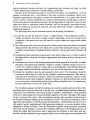
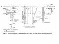
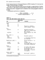
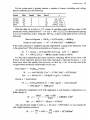
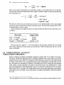
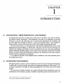
CHAPTER
i
INTRODUCTION
1-1 FOUNDATIONS: THEIR IMPORTANCE AND PURPOSE
All engineered construction resting on the earth must be carried by some kind of interfacing element called a foundation.1 The foundation is the part of an engineered system that
transmits to, and into, the underlying soil or rock the loads supported by the foundation and
its self-weight. The resulting soil stresses—except at the ground surface—are in addition to
those presently existing in the earth mass from its self-weight and geological history.
The term superstructure is commonly used to describe the engineered part of the system
bringing load to the foundation, or substructure. The term superstructure has particular significance for buildings and bridges; however, foundations also may carry only machinery,
support industrial equipment (pipes, towers, tanks), act as sign bases, and the like. For these
reasons it is better to describe a foundation as that part of the engineered system that interfaces
the load-carrying components to the ground.
It is evident on the basis of this definition that a foundation is the most important part of
the engineering system.
1-2 FOUNDATION ENGINEERING
The title foundation engineer is given to that person who by reason of training and experience
is sufficiently versed in scientific principles and engineering judgment (often termed "art")
to design a foundation. We might say engineering judgment is the creative part of this design
process.
The necessary scientific principles are acquired through formal educational courses in
geotechnical (soil mechanics, geology, foundation engineering) and structural (analysis, de-
1
TMs is also sometimes called the substructure.
sign in reinforced concrete and steel, etc.) engineering and continued self-study via short
courses, professional conferences, journal reading, and the like.
Because of the heterogeneous nature of soil and rock masses, two foundations—even on
adjacent construction sites—will seldom be the same except by coincidence. Since every
foundation represents at least partly a venture into the unknown, it is of great value to have
access to others' solutions obtained from conference presentations, journal papers, and textbook condensations of appropriate literature. The amalgamation of experience, study of what
others have done in somewhat similar situations, and the site-specific geotechnical information to produce an economical, practical, and safe substructure design is application of
engineering judgment.
The following steps are the minimum required for designing a foundation:
1. Locate the site and the position of load. A rough estimate of the foundation load(s) is
usually provided by the client or made in-house. Depending on the site or load system
complexity, a literature survey may be started to see how others have approached similar
problems.
2. Physically inspect the site for any geological or other evidence that may indicate a potential
design problem that will have to be taken into account when making the design or giving
a design recommendation. Supplement this inspection with any previously obtained soil
data.
3. Establish the field exploration program and, on the basis of discovery (or what is found in
the initial phase), set up the necessary supplemental field testing and any laboratory test
program.
4. Determine the necessary soil design parameters based on integration of test data, scientific
principles, and engineering judgment. Simple or complex computer analyses may be involved. For complex problems, compare the recommended data with published literature
or engage another geotechnical consultant to give an outside perspective to the results.
5. Design the foundation using the soil parameters from step 4. The foundation should be
economical and be able to be built by the available construction personnel. Take into account practical construction tolerances and local construction practices. Interact closely
with all concerned (client, engineers, architect, contractor) so that the substructure system
is not excessively overdesigned and risk is kept within acceptable levels. A computer may
be used extensively (or not at all) in this step.
The foundation engineer should be experienced in and have participation in all five of the
preceding steps. In practice this often is not the case. An independent geotechnical firm specializing in soil exploration, soil testing, design of landfills, embankments, water pollution
control, etc. often assigns one of its geotechnical engineers to do steps 1 through 4. The output
of step 4 is given to the client—often a foundation engineer who specializes in the design of
the structural elements making up the substructure system. The principal deficiency in this
approach is the tendency to treat the design soil parameters—obtained from soil tests of variable quality, heavily supplemented with engineering judgment—as precise numbers whose
magnitude is totally inviolable. Thus, the foundation engineer and geotechnical consultant
must work closely together, or at least have frequent conferences as the design progresses. It
should be evident that both parties need to appreciate the problems of each other and, particularly, that the foundation design engineer must be aware of the approximate methods used
to obtain the soil parameters being used. This understanding can be obtained by each having
training in the other's specialty.
To this end, the primary focus of this text will be on analysis and design of the interfacing
elements for buildings, machines, and retaining structures and on those soil mechanics principles used to obtain the necessary soil parameters required to accomplish the design. Specific
foundation elements to be considered include shallow elements such as footings and mats and
deep elements such as piles and drilled piers. Retaining structures will also be considered in
later chapters.
Geotechnical considerations will primarily be on strength and deformation and those soilwater phenomena that affect strength and deformation. With the current trend to using sites
with marginal soil parameters for major projects, methods to improve the strength and deformation characteristics through soil improvement methods will be briefly considered in
Chap. 6.
1-3 FOUNDATIONS: CLASSIFICATIONS
AND SELECT DEFINITIONS
Foundations may be classified based on where the load is carried by the ground, producing:
Shallow foundations—termed bases, footings, spread footings, or mats. The depth is generally D/B < 1 but may be somewhat more. Refer to Fig. 1-la.
Deep foundations—piles, drilled piers, or drilled caissons. Lp/B > 4+ with a pile illustrated in Fig. l-\b.
Figure 1-1 illustrates general cases of the three basic foundation types considered in this
text and provides some definitions commonly used in this type of work. Because all the definitions and symbols shown will be used throughout the text, the reader should give this figure
careful study.
The superstructure brings loads to the soil interface using column-type members. The loadcarrying columns are usually of steel or concrete with allowable design compressive stresses
on the order of 14O+ MPa (steel) to 1O+ MPa (concrete) and therefore are of relatively small
cross-sectional area. The supporting capacity of the soil, from either strength or deformation
considerations, is seldom over 1000 kPa but more often on the order of 200 to 250 kPa. This
means the foundation is interfacing two materials with a strength ratio on the order of several
hundred. As a consequence the loads must be "spread" to the soil in a manner such that its
limiting strength is not exceeded and resulting deformations are tolerable. Shallow foundations accomplish this by spreading the loads laterally, hence the term spread footing. Where
a spread footing (or simply footing) supports a single column, a mat is a special footing used
to support several randomly spaced columns or to support several rows of parallel columns
and may underlie a portion of or the entire building. The mat may also be supported, in turn,
by piles or drilled piers. Foundations supporting machinery and such are sometimes termed
bases. Machinery and the like can produce a substantial load intensity over a small area, so
the base is used as a load-spreading device similar to the footing.
Deep foundations are analogous to spread footings but distribute the load vertically rather
than horizontally. A qualitative load distribution over depth for a pile is shown in Fig. 1-1 b.
The terms drilled pier and drilled caisson are for the pile type member that is constructed by
drilling a 0.76 + -m diameter hole in the soil, adding reinforcing as necessary, and backfilling
backfill slope angle
Soil:
Cohesion
Base:
Soil:
Wall or
stem
Groundwater table
GWT
Backfill: soil,
ore,
coal,
grain,
etc.
Backfill parameters:
and c
Ground line or
dredge line
- Backface
Vertical stress
profile for B = L
at center
diam.
Qualitative
shaft load
profile
(c) Retaining structure
(b) Pile foundation. PP = tip, point,
or pile base load (units of kN)
(a) Spread foundation. Base contact pressure
p
q0 = — (units of kPa, usually)
BL
Figure 1-1
Definition of select terms used in foundation engineering. Refer to "tabulated" list of primary symbols after preface for unrecognized terms.
the cavity with concrete. Design and construction of piles and caissons will be considered in
more detail in Chaps. 16-19.
A major consideration for both spread footings (and mats) and piles is the distribution
of stresses in the stress influence zone beneath the foundation [footing or pile tip (or point)].
The theoretical distribution of vertical stress beneath a square footing on the ground surface is
shown in Fig. IAa. It is evident that below a critical depth of about 5B the soil has a negligible
increase in stress (about 0.02qo) from the footing load. This influence depth depends on B,
however. For example, if B = 0.3 m, the critical stress zone is 5 X 0.3 = 1.5 m, and if B =
3 m, the zone is 15 m for a zonal influence depth ratio of 1 : 10. Because these B values are
in a possible range beneath a large building, any poor soils below a depth of 2 m would have
a considerable influence on the design of the wider footings.
Any structure used to retain soil or other material (see Fig. 1-lc) in a geometric shape
other than that naturally occurring under the influence of gravity is a retaining structure. Retaining structures may be constructed of a large number of materials including geotextiles,
wood and metal sheeting, plain or reinforced concrete, reinforced earth, precast concrete elements, closely spaced pilings, interlocking wood or metal elements (crib walls), and so on.
Sometimes the retaining structure is permanent and in other cases it is removed when it is no
longer needed.
The foundations selected for study in this text are so numerous that their specialized study
is appropriate. Every building in existence rests on a foundation whether formally designed or
not. Every basement wall in any building is a retaining structure, whether formally designed
or not. Major buildings in areas underlain with thick cohesive soil deposits nearly always use
piles or drilled caissons to carry the loads vertically to more competent strata, primarily to
control settlement. Note that nearly every major city is underlain by clay or has zones where
clay is present and requires piles or caissons. Numerous bridges have retaining structures
at the abutments and spread foundations carrying the intermediate spans. Usually the abutment end reactions are carried into the ground by piles. Harbor and offshore structures (used
primarily for oil production) use piles extensively and for both vertical and lateral loads.
1-3.1
Other Foundations
Many other types of "foundations" that the geotechnical/foundation engineer may encounter
are not readily classified. These may include reinforcing the foundation of an existing building if it has undergone excessive settlement or so it can carry additional load if additional
height is added. They may involve removing an existing foundation (whole or in part) and
replacing it with a basement or other structure, i.e., putting the new foundation at a lower
depth. They may involve routing a tunnel (subway or utility) beneath an existing structure
or for some type of vibration control. In some of these cases no new foundation is designed.
Rather, the engineer must determine the magnitude of any potential adverse effect on the existing structure. If the adverse effect is intolerable, the engineer may need to devise a remedial
design.
These several types of "foundations" are so diverse—and are so often one of a kind—that
their study is not suitable for a general foundation engineering textbook. These types of design
require a geotechnical engineer with a solid base in geotechnical fundamentals (generally
with an advanced degree), some experience, a willingness to venture into the unknown, and
a willingness to draw on the experience of others through membership in the appropriate
technical societies.
1-4 FOUNDATIONS: GENERAL REQUIREMENTS
Foundation elements must be proportioned both to interface with the soil at a safe stress level
and to limit settlements to an acceptable amount. In the past 5O+ years few buildings (but
numerous embankment types) have failed as a result of overstressing the underlying soil.
However, excessive settlement problems are fairly common and somewhat concealed since
only the most spectacular ones get published.
Few modern buildings collapse from excessive settlements; however, it is not uncommon
for a partial collapse or a localized failure in a structural member to occur. More common
occurrences are unsightly wall and floor cracks, uneven floors (sags and slopes), sticking
doors and windows, and the like.
The variability of soil in combination with unanticipated loads or subsequent soil movements (e.g., earthquakes) can result in settlement problems over which the designer may have
little control. In other words, current state-of-the-art design methods may greatly reduce the
likelihood (risk factor) of settlement problems but do not generally provide a risk-free project.
In fairness, though, some problems are the direct result of poor design—either simple carelessness or lack of engineering ability. Yes, just as there are both competent and incompetent
doctors, lawyers, and other professionals, so there are competent and incompetent engineers!
A major factor that greatly complicates foundation design is that the soil parameters used
for the design are obtained before the project is started. Later when the foundation is in place,
it is on (or in) soil with properties that may be considerably modified from the original, either from the construction process or from installing the foundation. That is, the soil may be
excavated and/or replaced and compacted; excavations tend to remove load and allow the underlying soil to expand; driving piles usually makes soil more dense, etc. Any of these events
either directly alters the soil (replacement) or modifies the initially estimated soil strength
parameters.
As a result of the uncertainties in loads, in soil properties, and in attempts to account for
variability and any other factors, it is common practice to be conservative in designing this
part of the system. We may quickly note, however, that this being the most important part
but the most difficult to access if problems later develop, a conservative design or even an
overdesign has a better return on investment here than in other parts of the project.
Another factor that encourages conservative design is the fact that many geotechnical engineers tend to imply that their talents (and design recommendations) are better than those of
the competition. This generates a false sense on the part of the client that using that geotechnical engineer will produce a minimum cost foundation. When this happens and problems
later occur (unanticipated soil strata, water, excessive settlements, or whatever), the client is
very likely to litigate (i.e., sue). This possibility means that geotechnical engineers should be
candid about the status of the state of the art in this specialty and make the client fully aware
that precise soil parameters are difficult if not impossible to quantify and that at least some
design conservatism is prudent.
Design conservatism means that any two design firms are unlikely to come up with exactly
the same soil parameters and final foundation design. It would not be unusual for one firm
to recommend the base contact pressure qo of Fig. 1-la to be, say, 200 kPa whereas another
might recommend 225 or even 250 kPa—both with the use of spread footings. There might be
a problem in ethics, however, if one firm recommended 200 kPa and the other recommended
only 100 kPa, which would require a mat foundation or the use of piles. One of the recommendations is either overly optimistic (the 200 kPa) or realistic; the other is either realistic or
overly conservative. Being excessively conservative is an ethics problem, unless the client is
made aware of the several alternatives and accepts the more conservative recommendation
as being in his or her best interests.
In summary, a proper design requires the following:
1. Determining the building purpose, probable service-life loading, type of framing, soil profile, construction methods, and construction costs
2. Determining the client/owner's needs
3. Making the design, but ensuring that it does not excessively degrade the environment, and
provides a margin of safety that produces a tolerable risk level to all parties: the public,
the owner, and the engineer
1-5
FOUNDATIONS: ADDITIONAL CONSIDERATIONS
The previous section outlined in general terms requirements to be met in designing a foundation in terms of settlement and soil strength. We will now outline a number of additional
considerations that may have to be taken into account at specific sites.
1. Depth must be adequate to avoid lateral squeezing of material from beneath the foundation
for footings and mats. Similarly, excavation for the foundation must take into account that
this can happen to existing building footings on adjacent sites and requires that suitable
precautions be taken. The number of settlement cracks that are found by owners of existing
buildings when excavations for adjacent structures begin is truly amazing.
2. Depth of foundation must be below the zone of seasonal volume changes caused by freezing, thawing, and plant growth. Most local building codes will contain minimum depth
requirements.
3. The foundation scheme may have to consider expansive soil conditions. Here the building
tends to capture upward-migrating soil water vapor, which condenses and saturates the
soil in the interior zone, even as normal perimeter evaporation takes place. The soil in a
distressingly large number of geographic areas tends to swell in the presence of substantial
moisture and carry the foundation up with it.
4. In addition to compressive strength considerations, the foundation system must be safe
against overturning, sliding, and any uplift (flotation).
5. System must be protected against corrosion or deterioration due to harmful materials
present in the soil. Safety is a particular concern in reclaiming sanitary landfills but has
application for marine and other situations where chemical agents that are present can
corrode metal pilings, destroy wood sheeting/piling, cause adverse reactions with Portland cement in concrete footings or piles, and so forth.
6. Foundation system should be adequate to sustain some later changes in site or construction
geometry and be easily modified should changes in the superstructure and loading become
necessary.
7. The foundation should be buildable with available construction personnel. For one-of-akind projects there may be no previous experience. In this case, it is necessary that all
concerned parties carefully work together to achieve the desired result.
TABLE 1-1
Foundation types and typical usage
Foundation type
Use
Applicable soil conditions
Shallow foundations (generally DIB < 1)
Spread footings,
wall footings
Individual columns, walls
Any conditions where bearing
capacity is adequate for applied
load. May use on a single stratum; firm layer over soft layer or
soft layer over firm layer. Check
settlements from any source.
Combined footings
Two to four columns on
footing and/or space is
limited
Same as for spread footings
above,
Mat foundations
Several rcws of parallel
columns; heavy column
loads; use to reduce differential settlements
Soil bearing capacity is generally
less than for spread footings, and
over half the plan area would be
covered by spread footings. Check
settlements from any source.
Deep foundations (generally LPIB > 4 + )
Floating pile
In groups of 2 + supporting
a cap that interfaces with
column(s)
Surface and near-surface soils
have low bearing capacity and
competent soil is at great depth.
Sufficient skin resistance can be
developed by soil-to-pile perimeter to carry anticipated loads.
Bearing pile
Same as for floating pile
Surface and near-surface soils
not relied on for skin resistance;
competent soil for point load is at
a practical depth (8-20 m).
Drilled piers or
caissons
Same as for piles; use
fewer; For large column
loads
Same as for piles. May be floating or point-bearing (or combination). Depends on depth to competent bearing stratum.
Retaining structures
Retaining walls,
bridge abutments
Permanent material
retention
Sheeting structures
(sheet pile, wood
sheeting, etc.)
Temporary or permanent
for excavations, marine
cofferdams for river work
Any type of soil but a specified
zone (Chaps. 11, 12) in backfill is
usually of controlled fill.
fill
Retain any soil or water. Backfor waterfront and cofferdam
systems is usually granular for
greater drainage.
8. The foundation and site development must meet local environmental standards, including determining if the building is or has the potential for being contaminated with hazardous materials from ground contact (for example, radon or methane gas). Adequate air
circulation and ventilation within the building are the responsibility of the mechanical
engineering group of the design team.
Although not all of the preceding are applicable to a given project, it is readily apparent
that those that are tend to introduce much additional uncertainty into the system. This makes
the application of engineering judgment an even more important ingredient in the design
process.
1-6
FOUNDATIONS: SELECTION OF TYPE
Table 1-1 tabulates the use and application of the several general foundation types shown
in Fig. 1-1. Design of these several types will be taken up in detail in later chapters, but it
is useful at this point to obtain a general overview of when and where a particular type of
foundation is used.
Where the groundwater table (GWT) is present (see Fig. l-la), it is common to lower it
below the construction zone either permanently or for the duration of the construction work.
The GWT shown on Fig. l-la is below the footing and would probably be below the construction zone. If the GWT later rises above the footing level, the footing will be subject to
uplift or flotation, which would have to be taken into account.
If the groundwater table must be lowered either temporarily or permanently, it is usually
necessary to get approval from environmental protection agencies. Also there is a potential
problem of causing ground subsidence in the area surrounding the construction site if there
is significant lowering of the GWT. For this reason it is a common practice to construct water
barriers around the site perimeter and only pump out the interior.
1-7 THE INTERNATIONAL SYSTEM OF UNITS (SI)
AND THE FOOT-POUND-SECOND (Fps) SYSTEM2
We may define a system of units for computational purposes in terms of the fundamental
quantities of length, mass, and time as follows:
a. Meter, kilogram, second = mks; SI
b. Foot, pound, second = Fps; widely used in the United States through 1993-1995 but
almost nowhere else since about 1975.
Table 1-2 lists computational units (see also table inside back cover) and the abbreviations
that will be consistently used throughout the text. Refer to this table if you are not already
familiar with the abbreviation when later used. Units in this table generally follow those used
2
This section has been retained for "historical" purposes and for those few users who may need some aid in making
units conversions.
by the American Society for Testing and Materials (ASTM) Committee D-18 (soils and soil
testing), of which the author is a member.
The value of the gravitational constant g shown in the table is at approximately 45° latitude
and sea level. It varies about 0.5 percent based on latitude and elevation, but its use as a
constant will produce a negligible error for foundation work in most geographic locations on
the Earth.
In the general case the force is computed as
Mass X acceleration
Constant of proportionality r/
m •a
r/
TABLE 1-2
Units* and abbreviations used in this text
Unit
Abbreviations
used
Length
foot
inch
meter
ft
in.
m
Force
gram force
gf
pound force
Mass—symbol = m
gram
pound
pound force/g
lbf
g
Ib
slug
Weight/volume—symbol = y
pound/ft3
Newton/m3
pcf
N/m 3
Pressure
Newton/m2
Pa
pound/in2
pound/ft2
psi
psf
Density—symbol = p
mass/volume
kg/m3
slug/ft3
*Fps units primarily for historical purposes.
Comments
May use cm = centimeter =
m/100 or millimeter = m/1000
May prefix with k for kilo =
1000 g = kg = preferred SI unit,
Mg = 106 g, etc.
May use kilopound = kip = 1000
pounds
May prefix a kg, Mg, etc.
g = gravitational constant of 32.2
ft/s2 or 9.807 m/s 2
May have subscript as w = water, etc.
Or kips/ft3 = kef
May use kN/m 3 , MN/m 3 , etc.; for
soil use kN/m 3 as preferred unit
Pa = Pascal = N/m 2 ; may use
kPa, Mpa; kPa for soil pressure
May use kip/m.2 = ksi
May use kip/ft2 = ksf preferred
for soil pressure
May use g/cm3 = gram/cu cm
For the system units of primary interest, a number of sources (including most college
physics textbooks) give the following:
System
Mass
Length
Time
Force F
17
Sl(mks)
US(Fps)
US(Fps)
Metric
kg
slug
lb m
kg
m
ft
ft
m
s
s
s
s
N
lbf
1 lbf
kgf
1 kg • m/N • s2
1 slug • ft/lb • s2
32.2 lb m • ft/lb • s2
9.807 kg • m/kg f • s2
With this table, let us look at a 1 ft3 volume of sand that weighs and has a mass of 100
pounds (lbf and\bm obtained from F = m-a/iq = 100 X 32.2/32.2) as determined by placing
it on a set of laboratory scales. Using this 100 lbm, we have (using table in book cover) the
following:
Mass in kilograms = 100 lbm X 0.4536 kg/lbm = 45.36 kg
Volume in cubic meters = 1 ft3 X (0.3048 m/ft)3 = 0.02832 m3
If this sand is placed in a weightless bag and suspended by a spring in the laboratory, what
is the spring force? The vertical acceleration is, of course, g, and
SI: F = m(g)/r] = 45.36 kg(9.807 m/s2)/l kg • m/N • s2 - 444.8 N
Fps: F = 100(32.2)/32.2 = 100 lbf (usually written as 100 Ib)
It is this latter computation that causes confusion—obtaining 100 Ib of force from a 100
Ib mass. Closer inspection, however, shows this conclusion is valid only because g = 17. In
those cases where this equality does not exist, we have lbm ^ lbf. Let us also look at the
weight/volume and density relationships for this case:
Unit weight y = weightforce/volume
SI: 7 = 444.8 N/0.028 32 m3 = 15 706.2 N/m3 = 15.71 kN/m3
Fps: 7 = 100 lbf/1 ft3 - 100 lbf/ft3 (or pcf) = 0.100 kef
Density p = mass/volume
SI p = 45.36 kg/0.028 32 m3 = 1601.7 kg/m3 = 1.602 tonnes/m3
= 1.602 Mg/m3 = 1.602 g/cm3
An alternative computation in SI with application in soil dynamics computations is to
define density as
kN/m3
SI: p= —
=
1.602 X 9.807
—^807
_ ,A_ _ __
= 1M1
kN
2/ 4
s / m
Fps: p = 100/1 ft3 = 100 pcf = 0.100 kef
Also since the unit weight of water yw = 62.4 pcf = 9.807 kN/m3, we can compute the
unit weights between systems as
These unit weight relationships are particularly useful in converting between SI and Fps.
Also note the connection between the unit weight of soil/unit weight of water, giving directly
the soil density p as
P
=
y
^
15.71
= 9^O7
=
100
614
* *M
=
,
2
L6O28/Cm
- 1601.7 kg/m 3
= 1.602 kN s 2 /m 4
The first two forms for mass density just given are not dimensionally correct and require
conversion factors, which are not shown since they cancel. The last form, in units of kN-s 2 /m 4 ,
is dimensionally correct as given.
Some commonly used approximations are obtained from the table on the inside back cover
as follows:
Base Value
Suggest using
1 ksf - 47.88 kPa
2 ksf = 1 ton/ft2 = 95.76 kPa
1 kg/cm2 = 0.976 ton/ft2
50 kPa
100 kPa
1 ton/ft2 or 1 tsf
The last value of 1 kg/cm 2 — 1 tsf is the origin of the one-time common use of tons and
tsf by many engineers for pile loads and soil pressure. With SI being used, the ton3 and tsf
units are obsolete.
1-8 COMPUTATIONAL ACCURACY
VERSUS DESIGN PRECISION
Pocket or desktop calculators and digital computers compute with 7 to 14 digits of accuracy.
This gives a fictitiously high precision to computed quantities whose input values may have a
design precision only within 10 to 30 percent of the numerical value used. The reader should
be aware of this actual versus computed precision when checking the example data and output. The author has attempted to maintain a checkable precision by writing the intermediate
value (when a pocket calculator was used) to the precision the user should input to check
the succeeding steps. If this intermediate value is not used, the computed answer can easily
differ in the 1.0 to 0.1 position. The reader should also be aware that typesetting, transcribing,
and typing errors inevitably occur, particularly in misplaced parentheses and misreading 3
for 8, etc.
3
This is the 2000 Ib ton. The "metric" ton of 1000 kg is still used to some extent but is usually identified as "tonne."
The text user should be able to reproduce most of the digits in the example problems to
0.1 or less unless a typesetting (or other) error has inadvertently occurred. There may be
larger discrepancies if the reader uses interpolated data and the author used "exact" data
from a computer printout without interpolating. Generally this situation will be noted so that
the reader is alerted to potential computational discrepancies. The example problems have
been included primarily for procedure rather than numerical accuracy, and the user should
be aware of this underlying philosophy when studying them.
1-9 COMPUTER PROGRAMS IN FOUNDATION
ANALYSIS AND DESIGN
A large number of foundation engineering problems can be efficiently analyzed and/or designed using a digital computer. Particular advantages of using a computer accrue from these
features:
1. One is able to try a range of problem variables to obtain a feel for the effect of specifying,
or using, a particular set of soil parameters.
2. One can avoid having to use tabulated data or plotted curves, which usually require interpolation and excessive simplification of the foundation model.
3. One can minimize computational errors from these sources:
a. Erroneous key entry when using a calculator. The bad entry is (or should be) output to
paper using a computer so the input can be checked.
b. Omission of computational steps. A working computer program usually includes all the
design steps. A set of hand computations may not include every step for any number
of reasons (forget, not be aware of, carelessness, etc.).
c. Calculator chip malfunction not readily detected except by using two calculators. Computer chips are often internally checked on power-up, or output is so bad that chip errors
are visually detected.
4. With output to a printer one has a paper record of the problem for office files without the
necessity of transcribing data from intermediate steps. This avoids copy errors such as 83
for 38 and the like.
The major disadvantage of using a computer program is that it is difficult to write a first
generation, error-free program of real use in a design office. Program usability tends to increase with each revision (or history) level.
With the current wide availability of computer programs—many, such as those on the
included diskette, having a "history"—the advantages gained from program use far exceed
any perceived disadvantages. The author suggests that both geotechnical and foundation engineers should use computer programs whenever possible—and certainly be aware of what
computer program(s) each is likely to use for the given project.
This statement is made with full awareness of the possibility of program errors (or "bugs").
Fortunately, most geotechnical software is task-specific so that the possibility of program
errors or their not being detected is not so likely as for some of the large finite-element
or structural analysis programs that purport to solve a wide range of tasks. In any case, the
author cannot recall a single reported foundation design failure that can be attributed to a
bad 4 computer program.
It should be evident that computer programs vary widely in perceived quality, perceived
quality being defined here as problem limitations and "ease of use." Both users and programmers should be aware that it is difficult to predefine the full range of problem parameters
likely to be encountered in practice, so nearly any geotechnical program of significant value
is likely to have some built-in limitations. Ease of use is highly subjective and depends more
on user familiarity with a program than how easy it really is to use—many users like pulldown menus and graphics whereas others are quite content without these features. As a final
comment on computer programs, be aware that although business applications and games
usually have a market in the hundreds of thousands, geotechnical programs have a potential
market of only a few thousand. This small market means geotechnical software is likely to
be more expensive than other software and, to minimize development costs, it is not likely to
have many so-called user-friendly features.
One should routinely check the output from any computer program used for design or
analysis. The user is responsible for his or her design since it is impossible to write a computer
program with any usefulness that cannot be misused in some manner. Primarily for this reason
most computer programs are sold or licensed with a disclaimer making the user responsible.
Fortunately, most computer programs can be written to be somewhat self-checking, either
by writing back the input data or by providing output that can be readily identified as correct
(or incorrect) if the user understands or knows how to use the program. It should go without
saying that, if you do not know much about the specific problem being designed or analyzed,
you should first do some preliminary study before using a computer program on it.
This textbook encourages computer use in foundation engineering. Select programs are
furnished on the enclosed computer diskette in compiled format to save time for the text user.
All of the programs used or suggested for use are identified from the author's program library
and are available in source code with user's manuals individually or in a package on IBM
PC/AT type diskettes (5^-in. or 3.5-in.) at a reasonable5 cost from the author.
4
Generally if the program is "bad," the user finds this out by performing some kind of independent check and does
not use that program further in the design.
5
Please note that "reasonable" does not mean "free." There is a substantial cost just in reproducing a diskette,
providing a user's manual, and shipping.