Download Network Availability Program User Manual
Transcript
NAP Version 1.0 Network Availability Program User Manual NAP V1.0 Copyright © 2004 Isograph Limited All rights reserved. This document and the associated software contains proprietary information which is protected by copyright and may not be copied in whole or in part except with the prior written permission of Isograph. The copyright and the foregoing restrictions on the copyright extends to all media in which this information may be preserved. Isograph makes no representations or warranties of any kind whatsoever with respect to this document or its associated software. Isograph disclaims all liabilities for loss or damage arising out of the possession sale or use of this document or its associated software. Nap V1.0 Contents 1. INTRODUCTION............................................................................................ 1 2. THE NETWORK DIAGRAM ........................................................................ 3 3. PROGRAM OPERATION ............................................................................. 7 4. TUTORIAL .................................................................................................... 11 CONSTRUCTING A PART LIBRARY ...................................................................... 11 ADDING NETWORK ELEMENTS TO THE BLOCK LIBRARY .................................... 15 CONSTRUCTING A NETWORK DIAGRAM ............................................................. 18 PERFORMING AN ANALYSIS .............................................................................. 19 5. BUILDING A NAP PROJECT..................................................................... 21 ADDING PART GROUPS TO THE PART LIBRARY .................................................. 21 ADDING PART DEFINITIONS TO THE PART LIBRARY ........................................... 23 ADDING PART LISTS TO THE PART LIBRARY ...................................................... 26 ADDING BLOCK GROUPS TO THE BLOCK LIBRARY ............................................. 27 ADDING BLOCKS TO THE BLOCK LIBRARY ......................................................... 29 ADDING NETWORKS TO THE PROJECT ................................................................ 30 BUILDING A BLOCK LIBRARY DIAGRAM ............................................................ 31 BUILDING A NETWORK DIAGRAM ...................................................................... 32 CONNECTING TO SOCKETS ................................................................................. 33 6. MODIFYING BLOCK PARAMETERS ..................................................... 35 BLOCK PARAMETERS – GENERAL TAB .............................................................. 36 BLOCK PARAMETERS – PARTS TAB ................................................................... 39 BLOCK PARAMETERS – SOCKETS TAB ............................................................... 40 BLOCK PARAMETERS – COMMON CAUSE FAILURES TAB ................................... 41 BLOCK PARAMETERS – APPEARANCE TAB ......................................................... 42 7. MODIFYING CONNECTION PARAMETERS ........................................ 43 8. MODIFYING LABEL PARAMETERS ...................................................... 45 9. MODIFYING NODE PARAMETERS ........................................................ 47 10. MODIFYING BITMAP PARAMETERS.................................................. 49 NAP V1.0 11. PROJECT AND LIBRARY FILES............................................................ 51 PROJECT FILES .................................................................................................. 51 APPENDING NETWORK DATA ............................................................................ 53 LIBRARY FILES .................................................................................................. 54 OPENING A WORKBENCH V9.1 PROJECT ............................................................ 55 12. FINDING BLOCKS AND NODES ............................................................ 57 13. ORDERING BLOCKS ................................................................................ 59 ORDERING SHELVES AND SLOTS ........................................................................ 59 ORDERING BLOCKS AND SUB-BLOCKS............................................................... 60 14. PROJECT OPTIONS .................................................................................. 61 SETTING PROJECT OPTIONS ............................................................................... 61 PROJECT OPTIONS – GENERAL TAB ................................................................... 62 PROJECT OPTIONS – DEFAULTS TAB .................................................................. 63 PROJECT OPTIONS – UNITS TAB ........................................................................ 65 PROJECT OPTIONS – VIEW TAB ......................................................................... 66 PROJECT OPTIONS – ANALYSIS TAB .................................................................. 67 PROJECT OPTIONS – PRECISION TAB .................................................................. 69 PROJECT OPTIONS – COLOUR TAB ..................................................................... 70 PROJECT OPTIONS – LIBRARIES TAB .................................................................. 71 15. MODIFYING THE NETWORK DIAGRAM ........................................... 73 NETWORK DIAGRAM SCALING OPTIONS ............................................................ 73 MOVING NETWORK DIAGRAM OBJECTS ............................................................ 74 COPYING NETWORK DIAGRAM OBJECTS ............................................................ 75 16. THE GRID CONTROL............................................................................... 77 USING THE GRID CONTROL................................................................................ 77 GRID CONTROL - FILTER ................................................................................... 80 GRID CONTROL – GRID OPTIONS ....................................................................... 82 GRID CONTROL – FIND AND REPLACE ............................................................... 83 17. NETWORK ANALYSIS ............................................................................. 85 PERFORMING AN ANALYSIS ............................................................................... 85 ANALYSIS METHODS ......................................................................................... 86 DATA VERIFICATION ......................................................................................... 92 THE PAUSE ANALYSIS DIALOG .......................................................................... 93 THE RESULTS DIALOG ....................................................................................... 95 RESULTS GRAPHS ............................................................................................ 103 Nap V1.0 18. REPORTS .................................................................................................. 105 19. IMPORTING AND EXPORTING DATA............................................... 107 20. DATABASE STRUCTURE ...................................................................... 109 BLOCKS TABLE ............................................................................................... 110 PART GROUPS TABLE ...................................................................................... 111 PARTS TABLE .................................................................................................. 112 PROJECT OPTIONS TABLE ................................................................................ 113 CRITICALITY TABLE ........................................................................................ 114 CUT SETS TABLE ............................................................................................. 115 PATHS TABLE .................................................................................................. 116 RESULTS TABLE .............................................................................................. 117 21. INSTALLING NAP ................................................................................... 119 INSTALLATION INTRODUCTION ........................................................................ 119 INSTALLING ON A STANDALONE MACHINE ....................................................... 121 INSTALLING ON A NETWORK SERVER ............................................................... 123 INSTALLING ON A NETWORK CLIENT ............................................................... 125 22. LICENSING NAP...................................................................................... 129 FLEXNET LICENSE SERVER INTRODUCTION .................................................. 129 INSTALLING STANDALONE FLEXNET LICENSES............................................. 130 INSTALLING THE FLEXNET LICENSE SERVER ................................................ 131 ADDING LICENSES TO AN EXISTING FLEXNET LICENSE SERVER .................... 134 INSTALLING A SEPARATE FLEXNET LICENSE SERVER ................................... 135 THE FLEXNET ‘SELECT LICENSES’ DIALOG .................................................. 136 MONITORING FLEXNET LICENSES USING LMTOOLS .................................. 138 NAP V1.0 Introduction 1. Introduction The Network Availability Program (NAP) enables users to predict the availability of communication networks. The NAP network availability model utilises an extended Reliability Block Diagram (RBD) methodology that addresses the specific characteristics of network elements and their connections. The effectiveness of network restoration after single or multiple failures may therefore be modelled accurately in NAP. In addition to predicting network availability, NAP also provides criticality rankings that identify weak spots in the network. NAP provides many time-saving features to allow users to quickly construct the network diagram. These include a parts library facility that allows users to import their parts data in convenient groupings, a network element library facility that allows users to construct common network element diagrams and a fully interactive network diagram construction facility. One of the important features of NAP is that it allows the modelling of data flow in different directions along the same network path. This means that users need not be specific about the direction of data flow in selected parts of the network. NAP will then automatically determine the allowable paths between a source and target, and hence determine the minimal cut sets that determine the availability of the network. NAP allows you to quickly construct network diagrams using drag and drop facilities. Users may simply drag a network element or part from the library tree onto the network diagram. Once a network element is realised in the network diagram you may modify the default parts (control, power, interface cards etc.) associated with the element by selecting options from alternative part lists. Then the network element may be interactively connected to other elements, through a chosen interface, simply by clicking the mouse. Complex or simple networks may be modelled using NAP. Network elements may be logically modelled right down to part level using the powerful NAP pagination facility. Individual network element diagrams have been extended beyond traditional RBDs to allow users to model multiple interfaces and their interactions with common equipment. In addition, NAP models the effect of switching delays on network availability using Markov Analysis. Users may also restrict the analysis to network paths traversing a limited number of network elements (limiting the ‘hop’ NAP V1.0 1 Introduction number). This useful feature eliminates unrealistic ‘snake-like’ paths in complex networks. Failure data is normally specified at the part level. Failure rates or MTTFs (Mean Time to Failure) may be specified for cards, shelves etc. and ‘cuts per km per yr’ specified for cables (other units are available). Repair times may be specified at the network element or part level. NAP analyses the network diagram using sophisticated minimal cut set generation algorithms allowing the effects of common failures to be modelled correctly. A wide range of network parameters (availability, reliability, MTBF etc.) are calculated and presented to the user. Criticality rankings allow the user to identify weak spots and indicate the most effective way to improve network availability. The NAP Report Generator allows you to select from a range of standard reports or quickly design your own customised reports. You can design your own headers and footers, choose your own fonts, insert your own pictures, sort and filter data and much more. Paginated network diagram reports are automatically produced and can be transferred to other packages such as Microsoft Word in the form of Windows metafiles. You may also choose from a wide range of sophisticated scientific graphs and charts or create your own graphs and charts. You can display multiple graphs on the same page and easily modify scales, legends, titles etc. NAP provides a flexible import/export facility that allows the user to transfer data to and from Microsoft Access databases, Microsoft Excel spreadsheets and text delimited and fixed length files. 2 Nap V1.0 The Network Diagram 2. The Network Diagram NAP recognises the failure logic of the network from the network diagram entered by the user. The diagram represents how individual network element failures interact with other network element failures to prevent data flow between source and target nodes in the network. A network diagram entered into NAP (you may create more than one network diagram in the same project) specifies the possible communication paths between different network elements. The paths between network elements, which are defined with connections, may be directional or nondirectional. A directional connection indicates that data may flow in one direction only. The network diagram will contain block symbols normally representing the network elements and the cables connecting the elements together. Network Diagram Constructed in NAP Network elements with multiple interfaces must be connected to other network elements via a specific interface (chosen by the user when making the connection). Each network diagram must have a single source node and single target node defined at the highest level. The source and target node indicate to NAP that the availability calculation should represent the probability that data flow is maintained between the two nodes. Users may also define sub-networks within the network diagram (e.g. for modelling self-healing ring technology). These sub-networks may also have source and target nodes defined. NAP V1.0 3 The Network Diagram Typical network hierarchy The availability of an individual network element is determined by the availability of the shelves and cards that constitute the network element. Some network elements may contain redundancy arrangements designed to increase availability. In addition, network elements with multiple interfaces will often use common equipment. In order for NAP to correctly determine the availability of these arrangements it is necessary to draw an element diagram to represent the failure logic. In fact the element diagram is really no different from the network diagram. It is an extended reliability block diagram (RBD) that can handle multiple interfaces and multidirectional data flow. 4 Nap V1.0 The Network Diagram Typical Element Hierarchy Network and element diagrams consist of blocks and nodes connected together in parallel and series arrangements. The blocks in a network diagram usually represent network elements and cables. The nodes in a network diagram are used to position connecting lines and specify the data flow source and target for the availability calculation. The nodes in an element diagram are used to position connecting lines and specify vote arrangements. Element diagrams are usually constructed as part of the network element library in NAP. However, they may be constructed or modified by ‘paging down’ from a selected network element in the network view. During availability calculations NAP will be able to determine whether the system is failed or not by examining the network diagram entered by the user. The program does this by determining whether there are any open paths from the source node to the target node. For paths traversing network elements with multiple interfaces, NAP takes into account the interface connections made by the user. NAP V1.0 5 Program Operation 3. Program Operation NAP employs standard Windows menus and dialogs to control the operation of the program. This ensures that new NAP users may rapidly familiarise themselves with program operation with minimal reference to the user manual. A standard Windows on-line help facility is also provided including context-sensitive help for dialogs (accessed by pressing the Help button when the dialog is displayed). Pull-down menus and their options may be selected using the left mouse button. Accelerator keys are provided for selected menu options. For example, tapping the Delete key will delete selected symbols in the block diagram. On starting the program the NAP window will be displayed covering the full screen. This window may be resized or iconified at any time by selecting window reconfiguration options from the top right corner of the window border. NAP V1.0 7 Program Operation The principal pull-down menu options are positioned along the top of the main NAP window. Immediately below these menu options reside a group of controls which form a toolbar allowing the user to access some of the more extensively used menu options directly. Diagram mode tabs are positioned just below the toolbar. These tabs allow the user to display ‘Networks’, ‘Block Library’, ‘Tables’ or ‘Results’ data in the windows below the tabs. When the ‘Networks’ tab is selected the program will display project network diagrams in the right hand window. The user may navigate between different networks and different lower level page views of the same network by making selections from the combo-box above the right hand window. When the ‘Block Library’ tab is selected the program will display library block diagrams in the right hand window. The user may navigate between different blocks in the library by making selections from the combo-box above the right hand window. Selecting the ‘Page Down’ or ‘Page Up’ toolbar options will allow the user to navigate between different diagram pages for the same library block. Library blocks may be created to represent generic network element block diagram structures that may be copied into a network diagram. Library blocks may also be created to represent common cause failures that may affect more than one network element at the same time. When the ‘Tables’ tab is selected the program will display parts, components, elements or bitmap data in a table format. A tab at the bottom of the right hand window allows users to navigate between these table types. Find, replace and filter functions are available from the pulldown menus and toolbars. When the ‘Results’ tab is selected NAP displays criticality graphs. Criticality data is only displayed when the results are up to date. At the bottom of the screen is positioned a message strip. Note that this message strip may be used to provide help on the functionality of pulldown menu options. As a pull-down menu option is highlighted (but before it is selected) the message strip indicates its functionality. Summary help is provided on toolbar options by moving the mouse cursor over the 8 Nap V1.0 Program Operation appropriate option. The summary help information will appear immediately below the option. At the bottom right of the NAP screen a small secondary message strip shows the number of parts and blocks in the current project (including blocks associated with library network elements). The left hand NAP window always displays a tree control. The tree control enables the user to navigate the parts library, block library, networks and bitmap tables. The parts library consists of part category groups and part list groups. Each part must be attached below a part category group. Each part list definition must be attached below a part list group. Users may create part category groups to represent any type of categorisation and sub-categorisation of parts. This allows speedy navigation of the parts library to locate a certain part type. Part list groups may be created below other part list groups or below a part category group. The block library may consist of network element groups and common cause failure groups. Each network element in the block library must be attached below a network element group. Common cause failure blocks must be attached below a common cause failure group. Users may create network element groups to represent any type of categorisation and sub-categorisation of library network elements. Users may also create CCF groups to represent any type of categorisation and sub-categorisation of CCF blocks. The networks section of the tree allows users to navigate between different networks. The bitmap library allows users to create a table of bitmaps that may be used in network diagrams. To make a selection in the tree control the user must click the left button of the mouse over any object in the tree. The newly selected object will now be highlighted. NAP provides a facility to allow the user to open and close objects in the tree control. Closed objects do not display their children. This is an important facility when manipulating large projects as it allows the overall block diagram display to be reduced significantly in size. Objects may be opened or closed by clicking the left mouse button over the ‘+’ or ‘-’ box to the left of the appropriate object. Note that double clicking the left mouse button over some objects will result in that object's parameters being displayed in a parameter edit dialog. This is provided as a speed-up facility for editing parameters. NAP allows the selection of multiple objects in the tree control at the same time so long as the selected objects appear under the same parent. In order to select multiple objects in the tree control the user must hold down the control key whilst selecting additional objects by clicking the left mouse NAP V1.0 9 Program Operation button. If the user needs to select a large number of adjacent objects at the same time then this may be achieved using the shift key. If an object is selected with the shift key held down then all objects between the selected object and the previously selected component will be highlighted. Single objects may be deselected by holding the control key down and clicking the left mouse button. NAP provides pop-up menus containing some of the most frequently used options. To reveal a pop-up menu simply click the right mouse button with the cursor positioned in the left or right windows. 10 Nap V1.0 Tutorial 4. Tutorial This tutorial provides users with a basic step-by-step guide on how to construct and analyse a simple network using NAP. Before starting the tutorial open the demonstration NAP project demo.nap. Constructing a Part Library The NAP Part Library contains parts and part lists that may be attached to component blocks (blocks representing cards, cables and other components that may influence the availability of the network) in the network diagram. A single part type (defined uniquely by its vendor and part number) will normally be associated with a failure rate or mean time to failure (MTTF) that defines the failure characteristics of the part (the failure rate and MTTF are equivalent parameters and the user may decide which format is more suitable – failure rate = 1/MTTF). Any network component that is to be included in the network availability model must be defined as a part in the part library. Cables must therefore be defined as parts. They will be associated with a special failure parameter that specifies the failure rate per unit length of cable. In certain rare circumstances you might need to directly associate a part with an unavailability value rather than a failure rate or MTTF. A part library may contain many thousands of parts (even if they are not all being currently used in your network model) and therefore some method of grouping these parts is required to allow the user to easily locate the correct part when it needs to be associated with a block in the network diagram. NAP provides a part grouping facility that allows a user to construct groups and sub-groups through an unlimited number of hierarchical levels. Each part must be defined under a single group. You cannot define a part (with the same vendor and part number) twice in the same part library. As you add new parts to the part library you will be able to retrieve the part data simply by double-clicking on the part in the tree control in the left-hand NAP window. NAP V1.0 11 Tutorial Part and part list definitions organised into groups. The green book symbols represent part category groups, the green rectangular symbols represent part definitions, the yellow book symbols represent part list groups and the yellow block definitions represent part list items. Try double-clicking the left mouse button over some of the existing part definitions (green rectangular symbols) in the demonstration project library. A dialog will appear showing the parameters specified for each part. We will now create a new part group below an existing part group and then add a new part to the library. Select the ‘Interface cards’ part group with a single click of the left mouse button. Press the right mouse button over the ‘Interface cards’ part group in the tree control. The group will become selected and a pop-up menu will appear. Select the ‘Add Group’ option. The ‘Part Group’ dialog will appear allowing you to enter a new 12 Nap V1.0 Tutorial group description (say ‘High speed interface cards’). The ‘Category Group’ button should be selected. Select OK to create the new part group. Part Group Dialog We will now add a new part. Select the new part group with the right mouse button and select the ‘Add Part’ option from the pop-up menu. The Part dialog will appear allowing you to enter data for the part. You must provide a part number. You do not have to enter anything into the vendor field. However, a part is uniquely defined by the part number and part vendor, so if you are likely to have two parts with the same part number but originating from different vendors, you should complete the vendor field. Part Dialog In addition to defining individual parts the part library allows users to define part lists. You are not forced to define any part lists in the part NAP V1.0 13 Tutorial library. However, they can be very useful if you are later going to vary the part being used for a given function. For example, a slot on a given shelf within a network element could contain a power card with certain characteristics that could be provided by different power cards from different manufacturers. It would be useful to be able to select the part from an alternative part list of the appropriate type of power cards. Users may set up part lists of alternative parts in the part library and then associate the list with an individual component block in a network element. To define a part list you must first create a part list group. This may be done by creating a part group as above and changing the type to ‘List Group’ in the Part Group dialog. Part list groups may be created underneath part category groups or underneath other part list groups. The part list may then be defined by dragging a part definition (green rectangular block) onto a part list group (yellow book) in the tree control. Another way of adding to a part list is to select the part list group with the right mouse button and then select ‘Add Part to List’ from the pop-up menu. Two part lists defined in the part library (yellow symbols). The green symbols represent the part definitions. Identical parts (with the same vendor and part number) may be repeated in part lists but their original definitions (green symbols) can occur only once in the part library. 14 Nap V1.0 Tutorial Try adding one or two new part list groups and defining a list of parts below them using the demonstration project. You can copy existing lists and modify them if you wish using the Copy, Paste and Delete options on the right button pop-up menu. Adding Network Elements to the Block Library Once you have entered some parts into the part library you can start building a network diagram. However, many users will find it beneficial to build a library of common network element types before constructing the network diagram. This will allow common network element structures to be copied from the library into the network diagram reducing the time spent constructing a network model. The block library is also used to hold single blocks or block structures that represent high level essential services shared between multiple network elements. These blocks are known as ‘Common Cause Failure Blocks’ as failure of these blocks will result in the simultaneous unavailability of all the associated network elements. First we will deal with the use of the block library to construct a commonly occurring network element that may be used over and over again in network models. We will recommend a structure for the network element block diagram. However, this structure is only a recommendation for communication networks and the user may wish to organise network element block diagrams using a different scheme. Block diagrams are constructed in the right hand NAP window. We will first look at a library network element that has already been constructed in the demonstration project (and illustrated below). In the demonstration project select the ‘Block Library’ tab above the right hand window. Select the E1 network element in the tree control (this appears underneath the ‘Block Library’ and ‘COMPLEX’ nodes). You will then see the top level diagram representing library network element E1. It is often convenient to arrange network elements with respect to the shelves holding electronic cards. In this example we have constructed two shelf blocks. Double click the left mouse button with the cursor positioned over one of the shelf blocks. A dialog will appear showing the attributes of the block. The block type has been set to ‘Shelf’. This allows NAP to organise the blocks representing the slots on shelves at lower levels in the block diagram. NAP V1.0 15 Tutorial Select ‘Shelf 1’ and then select the ‘View, Page Down’ pull-down menu option or equivalent toolbar button. The block diagram for shelf 1 will now be displayed. Note that the connections in both diagrams so far are nondirectional (there are no arrows). This effectively indicates that data can flow in either direction through the connections. Double-click the left mouse button with the cursor positioned over the ‘Network interface 2’ block. Select the ‘Sockets’ tab in the dialog that appears. You will see that this block has been defined as a socket block. This tells NAP that a user can connect to this block from the external network. Cancel the dialog and double-click on the ‘Inter-shelf interface’ block. Select the ‘Sockets’ tab in the dialog that appears. You will see that this block has also been defined as a socket block but the socket has been restricted to next level connections. This indicates to NAP that the connection for this block may only be made between the shelf blocks at the level above. Select the ‘Network interface 2’ block and then select the ‘View, Page Down’ pull-down menu option or equivalent toolbar button. NAP will now display the component blocks at the lowest hierarchical level. Double-click 16 Nap V1.0 Tutorial on any of the component blocks. The ‘Library Component’ dialog will appear. Select the various tabs to view the data associated with the component. Library Component Dialog Library Network Elements are held in the Block Library underneath Block Groups. Block Groups may be created in a similar fashion to Part Groups. Simply select the Block Library node in the tree control or an existing Block Group with the right mouse button and select the ‘Add Group’ option from the pop-up menu. The Block Group dialog will appear allowing you to enter a description for the network element group. You may then create new network elements in the library by selecting a network element group with the right mouse button and then selecting the ‘Add Network Element’ option in the pop-up menu. A blank canvas will appear in the block diagram drawing area in the NAP right hand window. You may then construct a network element block diagram by selecting the Add pull-down menu options (or equivalent toolbar button) and placing blocks, nodes and connections in the diagram by clicking the left mouse button. When you want to ‘drill down’ to a lower level, select an existing block and then use the ‘View, Page Down’ pull-down menu option or equivalent toolbar button. You may then continue to add new blocks at the lower level. When you reach the lower level you may also create component blocks by NAP V1.0 17 Tutorial dragging the appropriate part or part list from the tree control into the diagram. Constructing a Network Diagram A network block diagram is constructed by first creating a top level network in the tree control and then adding blocks, nodes and connections to the network diagram in the right hand window. When you start a new project NAP automatically creates a single network (called N1) and places a source and target node within the drawing area representing the network block diagram. If you wish to create additional networks this may be done by selecting Networks in the tree control using the right button and then selecting ‘Add Network’ from the pop-up menu. You may add blocks, nodes and connections using the options on the Add pull-down menu. Alternatively, you may drag and drop parts and part lists from the part library. If you have constructed network elements in the network element library then you may also drag these into the network block diagram. NAP will produce a copy of the network element block structure that may be modified, if necessary, independently from the library structure. If you attempt to add a connection to or from a network element that has socket blocks defined below it (blocks with sockets defined below them are referred to as complex blocks by NAP) then NAP will reveal a ‘Socket Selection’ dialog allowing you to specify the interface block you wish to connect to. Each network diagram must have a single source and target node defined at the top level. During an analysis NAP will trace all possible paths from the source node to the target node (up to a user-specified network element hop count) taking into account any restrictions indicated by directed connections. Select the Networks tab above the right hand window for the demonstration project. Select network N1 in the tree control to display the top level network diagram. You will see that a network diagram has already been constructed using network elements from the network element library and cable parts directly from the part library. As you move the cursor over connection to network element the description of the lower level socket block will appear. Try dragging and dropping one or two more network elements from the network element library into the diagram. Drag 18 Nap V1.0 Tutorial in some cables from the part library and then connect them to the existing diagram. You do not need to construct a network diagram using the network element library at all if you wish. If you prefer you could simply add and connect new blocks directly to the network diagram. Component blocks could then be directly associated with a part in the part library. Performing An Analysis To perform an analysis select the ‘Analysis, Start’ pull-down menu option or equivalent toolbar button. If there are any logical errors in the network diagram you have constructed NAP will inform you of these errors and abort the analysis. If there are no errors NAP will proceed to determine the paths through the network. Then NAP will determine the minimal cut sets for each network and for simple blocks defined within each network. The minimal cut sets represent minimal combinations of failures that would result in loss of network availability (the network is assumed to be available if at least one path is maintained between the source and target nodes). The probability of the cut sets is determined and the ‘network unavailability’ and other network performance parameters are determined by the program. The ‘network unavailability’ is the probability that the network will be unavailable at any time. After performing an analysis NAP will display a results dialog displaying the various predicted performance parameters. The results dialog will also display criticality rankings. Criticality rankings indicate the sensitivity of network availability and failure frequency to the reliability of individual blocks in the network diagram. This allows users to determine the weak links in the network. NAP V1.0 19 Tutorial Results Dialog Displaying Summary Parameters for the Network 20 Nap V1.0 Building a NAP Project 5. Building a NAP Project Adding Part Groups to the Part Library To create a new part group select the ‘Part Library’ object or another existing part group in the tree control and then choose the ‘Add Group’ pop-up menu option (reveal the pop-up menu by pressing the right mouse button over the selected object). Alternatively, use the ‘Add, Group’ pulldown menu option or equivalent toolbar button. A dialog will appear allowing you to specify the following parameters. Part Group ID A unique ID for the part group of up to 32 characters. Description A description for the part group of up to 120 characters. Category Group Select this setting if you wish to create library part definitions beneath the group. Library part definitions uniquely define the characteristics and failure data associated with a part. List Group Select this setting if you wish to define a parts list below the part group. A parts list is a list of existing parts in the parts library. A parts list may be created by dragging existing parts onto the part list group in the tree control. Parts lists are created to allow a list of alternative parts to be assigned to a component in the block diagram. NAP V1.0 21 Building a NAP Project The Part Group Dialog 22 Nap V1.0 Building a NAP Project Adding Part Definitions to the Part Library The part library must contain at least one part category group before a new part may be added to the library. To create a new part select an existing part category group in the tree control and then choose the ‘Add Part’ pop-up menu option (reveal the pop-up menu by pressing the right mouse button over the selected object). Alternatively, use the ‘Add, Part’ pull-down menu option or equivalent toolbar button. A dialog will appear allowing you to specify the following parameters. Part Number The part number (up to 32 characters). The part number and vendor fields uniquely identify the part. Vendor The vendor (up to 32 characters). The part number and vendor fields uniquely identify the part. Description A description for the part group of up to 120 characters. Type The part type. The user may choose from <unspecified>, card, cable or shelf. Failure Data Format The failure data entry format. Valid options are failure rate, MTTF (mean time to failure) and ‘w and Q’. If the ‘w and Q’ option is selected the failure frequency (w) and unavailability (Q) are entered directly by the user. Failure Rate The failure rate for <unspecified>, card or shelf parts. This parameter is not displayed for cable parts. The parameter is not displayed for <unspecified>, card or shelf parts if the MTTF or ‘w and Q’ failure data format is selected. NAP V1.0 23 Building a NAP Project MTTF The MTTF (mean time to failure) for <unspecified>, card or shelf parts. This parameter is not displayed for cable parts. The parameter is not displayed for <unspecified>, card or shelf parts if the ‘failure rate’ or ‘w and Q’ failure data format is selected. w The failure frequency for <unspecified>, card or shelf parts. This parameter is not displayed for cable parts. The parameter is not displayed for <unspecified>, card or shelf parts if the ‘failure rate’ or ‘MTTF’ failure data format is selected. Q The unavailability for <unspecified>, card or shelf parts. This parameter is not displayed for cable parts. The parameter is not displayed for <unspecified>, card or shelf parts if the ‘failure rate’ or ‘MTTF’ failure data format is selected. Cut Rate The probable number of cable cuts per unit length per unit time. This parameter is only displayed if a cable part type is selected. Default MTTR The default mean time to repair the part. This value is used to initialise the block MTTR when a part is dragged to the drawing area to create a new block. It is also used to specify the MTTR for ‘Single Element Common Cause Parts’ associated with a network element (defined in the common cause failures tab of a network element dialog). Bitmap The bitmap associated with the part. If a block is created by dragging a part into the right window then the specified bitmap will be associated with the newly created block. 24 Nap V1.0 Building a NAP Project Part Dialog for a Card NAP V1.0 25 Building a NAP Project Adding Part Lists to the Part Library The part library must contain at least one part list group before a new record may be added to a part list. To create a new record in a list select an existing part list group in the tree control and then choose the ‘Add Part to List’ pop-up menu option (reveal the pop-up menu by pressing the right mouse button over the selected object). Alternatively, use the ‘Add, Part to List’ pull-down menu option or equivalent toolbar button. A dialog will appear allowing you to select the part you wish to add to the list. Part Selection Dialog An alternative method of adding a record to a part list is to drag and drop the part onto the part list group using the tree control. 26 Nap V1.0 Building a NAP Project Adding Block Groups to the Block Library The block library must contain at least one block group before a new block may be added to the library. There are two types of block groups – network element groups and common cause failure (CCF) groups. Network element groups contain block diagrams representing common network element arrangements. These library network element block diagrams may be copied into a NAP project to represent elements in the network diagram. CCF groups contain block diagrams that represent common failures that will cause multiple network elements to fail at the same time. To create a new block group select the ‘Block Library’ object or another existing block group in the tree control and then choose the ‘Add Group’ pop-up menu option (reveal the pop-up menu by pressing the right mouse button over the selected object). Alternatively, use the ‘Add, Group’ pull-down menu option or equivalent toolbar button. A dialog will appear allowing you to specify the following parameters. Block Group ID A unique ID for the element group of up to 32 characters. Description A description for the element group of up to 120 characters. Network Element Group Indicates that the group is to contain block diagrams representing common network element arrangements. Common Cause Failure Group Indicates that the group is to contain block diagrams representing common cause failures that affect multiple network elements at the same time. NAP V1.0 27 Building a NAP Project Block Group Dialog 28 Nap V1.0 Building a NAP Project Adding Blocks to the Block Library The block library must contain at least one block group before a new block may be added to the library. To create a new block select an existing block group in the tree control and then choose the ‘Add Network Element’ (for network element groups) or ‘Add Common Cause Failure’ (for common cause failure groups) pop-up menu options (reveal the pop-up menu by pressing the right mouse button over the selected object). Alternatively, use the ‘Add, Network Element’ pull-down menu option or equivalent toolbar button. A new ‘top-level’ network element or common cause failure block will be added to the library. The user may then add blocks to the blank drawing area representing the block in the right window. NAP V1.0 29 Building a NAP Project Adding Networks to the Project To create a network select the ‘Networks’ object in the tree control and then choose the ‘Add Network’ pop-up menu option (reveal the pop-up menu by pressing the right mouse button over the selected object). Alternatively, use the ‘Add, Network’ pull-down menu option or equivalent toolbar button. A network object will be added to the tree control and the right hand window will display a blank canvas to receive the network drawing. Double-clicking on the network tree object will reveal a dialog that allows the user to modify the following network parameters. General Tab Reference ID A network reference ID of up to 32 characters. Description A description of the network of up to 120 characters. Notes Notes of up to 255 characters. Network Dialog 30 Nap V1.0 Building a NAP Project Building a Block Library Diagram A user may construct a block library diagram by placing blocks and nodes in the diagram area and then linking these blocks and nodes using connections. The blocks may represent sub-elements and components (normally associated with common equipment and interface cards and shelves). One way to quickly build a block library diagram is to drag and drop a part list group or an individual part from the part library into the diagram area. NAP will then automatically draw a block in the diagram area and assign the part list or individual part to the block. Blocks may be placed in the element diagram using the following methods. A part may be created using drag and drop from the part library. Users may also select the ‘Add, Block’ pull-down menu option or equivalent toolbar button and place the block in the diagram using the left mouse button. A structure may also be created below an existing block by selecting the block and then selecting the ‘View, Page Down’ pull-down menu option or equivalent toolbar button. Alternatively, users may copy and paste existing blocks. Note that the paste option will copy a block (and its associated structure if it contains sub-blocks) maintaining the reference ID for the block. Paste special should be used to create blocks with a new reference ID. Blocks with the same reference ID are used to represent common cause failures. Nodes are placed in the diagram by selecting the ‘Add Node’ pull-down menu option or equivalent toolbar button and then placing the node in the diagram using the left button of the mouse. NAP V1.0 31 Building a NAP Project Building a Network Diagram A user may construct a network diagram by placing blocks and nodes in the diagram area and then linking these blocks and nodes using connections. The blocks will represent network elements and components (associated with a part). Component blocks added to the highest level of the network diagram will normally represent cables. Network elements would normally be extracted from the block library. If this is the case their constituent components (shelves, default cards etc.) will be automatically constructed on the pages below the network element. They could, however, be constructed totally in the network diagram if required. Blocks may be placed in the network diagram using the following methods. A part or network element may be created using drag and drop from the part library or block library respectively. Users may also select the ‘Add, Block’ pull-down menu option or equivalent toolbar button and place the block in the diagram using the left mouse button. A structure may also be created below an existing block by selecting the block and then selecting the ‘View, Page Down’ pull-down menu option or equivalent toolbar button. Alternatively, users may copy and paste existing blocks. Nodes are placed in the diagram by selecting the ‘Add Node’ pull-down menu option or equivalent toolbar button and then placing the node in the diagram using the left button of the mouse. 32 Nap V1.0 Building a NAP Project Connecting to Sockets When making connections to network elements that contain ‘socket’ blocks or nodes (blocks or nodes with the socket flag switched on), NAP will display the Socket Selection Dialog. This dialog displays a tree structure containing lower level blocks. At component block level the associated parts are displayed. Socket blocks (normally associated with interface cards) are displayed in red in the tree control. The user may select the appropriate socket block to connect to by double-clicking the left mouse button with the cursor positioned over the socket block in the tree. Alternatively, select the connection socket and press the return key. Socket Selection Dialog NAP V1.0 33 Modifying Block Parameters 6. Modifying Block Parameters Block parameters may be modified by double clicking the left mouse button with the cursor positioned over the block in the network diagram. Alternatively, select the block and then select the ‘Edit, Selection’ pulldown menu option. A dialog will be revealed allowing the user to modify the following parameters. Selecting a Block in the Network Diagram NAP V1.0 35 Modifying Block Parameters Block Parameters – General Tab Reference ID A reference ID of up to 32 characters. Description A description of the element of up to 120 characters. Notes Notes of up to 255 characters. Simple/Complex Indicates whether the block is a simple or complex block. Blocks with no sockets defined at a lower level in the block diagram structure will be considered to be simple blocks. Other blocks are considered to be complex. Type The type of block. The type may be <unspecified>, Network Element or Shelf. This field is only displayed for super blocks. If you select the ‘Network Element’ type then the block will contribute to the ‘hop count’ during the analysis. During an analysis users may specify a ‘hop count’ limit for the paths being generated in a network. If you select the ‘Shelf’ type then lower level component blocks that have slot names will be grouped together under the shelf description when selecting alternative part types for network elements. Failure Model The failure model may only be set for component blocks. If the failure model is set to ‘Revealed Failure’ NAP will assume that the component is immediately repaired. The unavailability of the component will be given by Q= 36 λ λ+µ Nap V1.0 Modifying Block Parameters where λ is the failure rate and µ is the repair rate of the component. If the failure model of the component is set to ‘Dormant Failure’ NAP will assume that component failures are hidden until a test takes place. The unavailability of the component will be given by Qmean = where Qmean = λ = MTTR = = τ λ .τ − (1 − e − λτ ) + λ . MTTR.(1 − e − λτ ) λ .τ + λ . MTTR(1 − e − λτ ) Mean unavailability value Failure rate Mean time to repair Test interval MTTR The mean time to repair the component. This parameter may only be set for component blocks. Test Interval The test interval for the component. This parameter may only be set for component blocks with the ‘Dormant Failure’ failure model type. Quantity The quantity of the element or sub-element to be modelled. A quantity may only be set for modular blocks and components. Vote Number The number of elements or sub-elements required to be working for success. This value must be between 1 and the quantity specified. A vote number may only be set for modular blocks and components. NAP V1.0 37 Modifying Block Parameters Set MTTR for Components Selection of this option allows the user to specify a new MTTR value for all the components (blocks with no structure below them) defined below the block. This option will not be displayed for component blocks. Set Test Interval for Components Selection of this option allows the user to specify a new test interval for all the components (blocks with no structure below them) defined below the block. This option will not be displayed for component blocks. Path Logic The path logic may be set to ‘Probabilistic’ (default), ‘Open’ or ‘Closed’. If the path logic is set to ‘Probabilistic’ the component block will be assigned a probability (unavailability) based on the failure and repair data associated with the component block. If the path logic is set to ‘Open’ NAP will assume the component is always unavailable (i.e. its probability of failure is one). If the path logic is set to ‘Closed’ NAP will assume the component is always available (i.e. its probability of failure is zero). Cable Length This parameter will only be required if the assigned part is a cable. It is the length of the cable represented by the block. 38 Nap V1.0 Modifying Block Parameters Block Parameters – Parts Tab Shelf The shelf for which parts are to be selected. NAP automatically determines the different shelf identifiers from the shelf names given to the components associated with a network element. This list is only displayed for non-component blocks. Slot Parts Alternative parts for the network element may be selected from the list boxes. These lists are only displayed for non-component blocks. Part ID The part associated with the component block. This list is only displayed for a component block. Alternative Parts List The parts list group containing the alternative parts for the component block. This list is only displayed for a component block. Alternative Parts The alternative parts in the selected alternative parts list. Shelf Name If the component block is positioned underneath a ‘shelf’ block then the description or name of the shelf block will be displayed. Slot Name If the component block represents a card positioned on a shelf then the slot name corresponding to the block should be entered. NAP V1.0 39 Modifying Block Parameters Block Parameters – Sockets Tab Socket Indicates that the block may be connected to from a higher level in the block diagram hierarchy. Restrict Socket to Next Level Connections Indicates that connections may only be made to the socket block from the next level up in the block diagram hierarchy. 40 Nap V1.0 Modifying Block Parameters Block Parameters – Common Cause Failures Tab Single Element Common Cause Parts A list of parts that will cause the entire element (block) to be unavailable if the part were to fail. For example, ventilation equipment failure might render an entire element unavailable. Use the Add and Delete buttons to add or delete parts from the list. Multiple Element Common Cause Failure Blocks A list of common cause failure blocks (these blocks are defined underneath a common cause failure group in the block library) that will cause the element to fail. The same common cause failure blocks may also be assigned to other network element blocks in the network diagram. Failure of a common cause failure block will result in all network elements associated with the block becoming unavailable. Use the Add and Delete buttons to add or delete blocks from the list. NAP V1.0 41 Modifying Block Parameters Block Parameters – Appearance Tab Fill Colour The background fill colour for the block in the diagram. The background colour will only be visible if a bitmap is not selected for the block. Bitmap The bitmap to be displayed in the block rectangle in the diagram. 42 Nap V1.0 Modifying Connection Parameters 7. Modifying Connection Parameters Connection parameters may be modified by double clicking the left mouse button with the cursor positioned over the connection in the network diagram. Alternatively, select the connection and then select the ‘Edit, Selection’ pull-down menu option. A dialog will be revealed allowing the user to modify the following parameters. Description A description of up to 16 characters. The description will appear alongside the connection in the diagram if the ‘Show Connection Descriptions’ check box is selected in the Project Options Dialog. Appearance The appearance of the connection in the diagram. The user may choose Horizontal/Vertical or Diagonal. Directional Logic Determines whether data flow is directed (single direction only) or undirected (flow allowed in both directions). NAP V1.0 43 Modifying Label Parameters 8. Modifying Label Parameters Label parameters may be modified by double clicking the left mouse button with the cursor positioned over the label in the network diagram. Alternatively, select the label and then select the ‘Edit, Selection’ pulldown menu option. A dialog will be revealed allowing the user to modify the following parameters. Label Text Label text will appear inside the label frame in the network diagram. If a bitmap label is specified then the text will be replaced by the bitmap. Bitmap Label If the Bitmap Label check box is selected then the specified bitmap will be displayed within the label frame in the network diagram. Border The Border check box determines whether the label has a border. Font Selection of the Font button will prompt NAP to display a standard Windows font selection dialog allowing the user to choose the required font for the label. Horizontal Alignment The Horizontal Alignment options allow the user to choose how text will be aligned with the label in the network diagram. Options are left, centre and right alignment. Bitmap The Bitmap Combo-Box will only appear if the Bitmap Label option is selected. The Combo-Box allows the user to select the bitmap to appear in the label. NAP V1.0 45 Modifying Node Parameters 9. Modifying Node Parameters Node parameters may be modified by double clicking the left mouse button with the cursor positioned over the node in the network diagram. Alternatively, select the node and then select the ‘Edit, Selection’ pulldown menu option. A dialog will be revealed allowing the user to modify the following parameters. Node ID A unique identifier for the node of up to 32 characters. Vote Number The node Vote Number indicates the number of connected inputs required to be available to ensure availability of the sub-system defined to the left of the node in the network diagram. Type The mode type. Node type options are intermediate (default), source and target. A single source and target node must be set for each network in the top level diagram. The source and target nodes affect the analysis results for the network. NAP will determine the availability of data communication between the source and target nodes during an analysis. Switching Delay If the switching delay is non-zero NAP will use Markov Analysis to determine the decrease in availability of blocks connected to the node due to switching. Switching delays should only be specified for nodes on the right hand side of a parallel arrangement of simple blocks. The simple blocks may be super blocks (with structures below them) but should not contain any common failures. Nodes with non-zero switching delays may only be created in simple block diagrams with directional connections. In effect a node with a non-zero switching delay defines a group of blocks in a single switching group. The unavailability value of cut sets containing more than one block in a switching group will increase due to the effects of switching delays. NAP uses Markov analysis to determine this increase in unavailability. NAP V1.0 47 Modifying Node Parameters Specifying a switching delay of 60 seconds for the node to the right of blocks B and C indicates they belong to a switching group. NAP works back from a switching node until it meets another node to terminate the switching group. Another valid arrangement is illustrated below. Socket Indicates that the node may be connected to from a higher level in the block diagram hierarchy. Restrict Socket to Next Level Connections Indicates that connections may only be made to the socket node from the next level up in the block diagram hierarchy. 48 Nap V1.0 Modifying Bitmap Parameters 10. Modifying Bitmap Parameters To modify a bitmap’s parameters select the appropriate bitmap in the tree control followed by selection of the ‘Edit, Selection’ pull-down menu option. Alternatively, double-click the left mouse button with the cursor over the bitmap in the tree control. The Bitmap Dialog will appear allowing you to modify the following parameters. Bitmap ID A unique identifier for the bitmap of up to 32 characters. Description A description of the bitmap of up to 120 characters. Bitmap File Name The bitmap file name. The location of the bitmap can either be typed directly in the ‘Bitmap File Name’ field or the ‘Browse’ button may be used to navigate the file system. The bitmap is displayed in the rectangle in the lower centre of the dialog. Resize Frame If the ‘Resize Frame’ button is selected NAP will resize the block or label dimensions to fit the bitmap at the default magnification for the network diagram. Stretch to Frame If the ‘Stretch to Frame’ button is selected NAP will resize the bitmap to fit the block or label dimensions when it is assigned to a diagram object. Clip to Frame If the ‘Clip to Frame’ button is selected NAP will clip the bitmap to fit the block or label dimensions if the dimensions of the bitmap are greater than those of the block or label. If the bitmap is smaller than the block or label to which it is assigned, then the bitmap position will be centralised within the block or label frame. NAP V1.0 49 Modifying Bitmap Parameters Store in Project If the ‘Store in Project’ option is selected the bitmap definition will be stored within the NAP project rather than as an external bitmap file. 50 Nap V1.0 Project and Library Files 11. Project and Library Files Project Files A NAP project file contains all the data relating to a given project except for the external bitmap files associated with library bitmaps. This allows a user to recover all the entered input parameters, library data and calculation results associated with the project. When a NAP run is initiated the program will automatically open the project file in use when the last run was terminated. The network diagram and all the associated data will then be immediately available for further editing. A project file is given the extension .NAP by default. You may override the extension if you wish but it is not recommended. The principal elements of a NAP project may be viewed in the tree control in the left window once the project has been opened. A NAP project will contain library and network data. Library data may be created directly when editing a project (local library data) or may be imported by attaching a library file (external library data). Although NAP allows users to mix these different library data sources in the same project, it is recommended that the user choose between the two methods. If library data is likely to be shared between many projects then it is recommended that users create external library files and then attach these files to projects before building the network diagrams. NAP V1.0 51 Project and Library Files NAP project files are created or replaced when the ‘File, Save Project’ or ‘File, Save Project As’ menu options are selected. NAP will provide a warning if you do not save modified project data before starting a new project or exiting the program. An existing project may be modified by selecting the ‘File, Open Project’ option and selecting or entering the appropriate file name using the standard ‘Open File’ dialog which will be displayed by the program. The ‘File, New Project’ option clears the existing data ready for starting a new project. Recently modified project files may be opened simply by selecting the ‘File, Recent Projects’ pull-down menu option. The Recent Projects Dialog will be displayed allowing the user to select the required project directly from a list. 52 Nap V1.0 Project and Library Files Appending Network Data To append network data from another NAP project file select the ‘File, Append Network Data’ pull-down menu option. A File Open Dialog will appear allowing you to choose the NAP project file containing the data to be appended. This option will append the network block diagrams and will attach any external libraries that are attached to the source project. Common cause failure blocks will also be appended. Network element library blocks will not be appended unless they are part of an attached external library. If NAP cannot locate a part, part list or bitmap attached to an incoming block a warning will be given. This will occur if parts are created in the local libraries for the appended project rather than in external libraries. Matching network block reference IDs are renamed during the append operation. NAP V1.0 53 Project and Library Files Library Files NAP allows you to create and maintain library files that contain part, block and bitmap library data. Library files are distinct from project files in that they only contain library data and do not contain any network data. You may connect one or more library file to a single project. The project maintains a copy of the library data within the project. Library data may be updated by re-attaching a library file to a project. You do not need to create any library files to construct and analyse a network in a NAP project. Part, block and bitmap library data may be defined locally within a project and connected to the appropriate blocks. However, if you are creating multiple project files that are managed amongst different groups of analysts, it is clearly an advantage to be able to create a central library (or set of libraries) containing common network elements and the associated parts. These libraries may then be attached, as required, to individual projects. To create a new NAP library file first select the ‘File, New Library’ pulldown menu option. Add the library parts, part lists, library blocks and bitmaps as required. Then select the ‘File, Save Library’ pull-down menu option to save the data to a library file. NAP library files should be given the extension ‘.npl’. You may edit an existing library file using the ‘File, Open Library for Editing’ pull-down menu option. After editing the data use the ‘File, Save Library’ or ‘File, Save As Library’ pull-down menu options to save the modified library data. If you have created parts and blocks in the local library of a project you can save the library information to a library file using the ‘File, Save Library’ pull-down menu option. When you wish to access a library from within a project, select the ‘File, Attach Library to Project’ pull-down menu option. When you are constructing a network in a project you will be connecting blocks to part definitions within the attached libraries. Take care not to delete the local part definitions in the project or you will lose the logical link between the block and part definition. 54 Nap V1.0 Project and Library Files Opening a Workbench V9.1 Project NAP provides a facility to convert Reliability Workbench V9.1 project files into NAP format. NAP will only convert data entered into the RBD module of Reliability Workbench. NAP will store Reliability Workbench generic models in the NAP part library. Conversion of Reliability Workbench ‘Standby’ models is not supported. To convert Reliability Workbench RBD data into NAP format select the ‘File, Open Workbench V9.1 File’ pull-down menu option. A Windows ‘Open’ dialog will appear allowing you to select the Reliability Workbench file you wish to convert. If you already have a project open then you must save any data before performing the conversion. NAP V1.0 55 Finding Blocks and Nodes 12. Finding Blocks and Nodes The ‘Tools, Find’ menu options provide an alternative method of project navigation. Selection of the appropriate ‘Find’ option will result in the Find Block or Find Node dialogs being displayed. Show First The ‘Show First’ button will draw the first diagram in which the selected object is found. Show Next The ‘Show Next’ button will draw the next diagram in which the selected object is found. This button is not displayed when searching for nodes. Find Block Dialog NAP V1.0 57 Ordering Blocks 13. Ordering Blocks Ordering Shelves and Slots Users may specify the order that shelves and slots will appear in the ‘Parts’ tab within the network element dialog. This may be achieved by selecting the ‘Tools, Order Shelves and Slots’ pull-down menu option. A dialog will appear allowing the user to specify the shelf and slot order. Only shelves and slots below the selected network element (or other super block) will be shown in the dialog. This facility will normally be used when creating network elements in the library. Only shelf blocks and blocks with slot names will be shown in the dialog. Shelf and Slot Ordering Dialog NAP V1.0 59 Ordering Blocks Ordering Blocks and Sub-Blocks Users may specify the order that blocks should be arranged in the internal project database. This may be achieved by selecting the ‘Tools, Order Blocks and Sub-Blocks’ pull-down menu option. A dialog will appear allowing the user to specify the block and sub-block order. Only blocks and sub-blocks below the selected block will be shown in the dialog. Block and Sub-block Ordering Dialog 60 Nap V1.0 Project Options 14. Project Options Setting Project Options Project options may be modified by double clicking the left mouse button with the cursor positioned over the project symbol at the top left corner of the tree control. Alternatively, select the ‘Tools, Options’ pull-down menu option. A Project Options Dialog will then appear allowing the user to modify project parameters. NAP V1.0 61 Project Options Project Options – General Tab Parameters that may be set in this tab are described below : Project Description A description for the project of up to 120 characters. Auto Backup If the Auto Backup check box is set then an automatic backup will be performed at the specified interval. Project data will be written to a file with the same base name as the current project but with a '.bak' extension. This file can be opened via the normal File, Open menu option. Show Transfer Page Numbers on Printed Diagrams This check box allows the user to specify that transfer page numbers will appear on printed multi-page diagrams. Cut Set Delimiter The delimiter to be used between block names in cut set lists. Show Network Element Structure in Diagram Reports If this option is set NAP will show the block diagram structure for network elements in printed reports. 62 Nap V1.0 Project Options Project Options – Defaults Tab Parameters that may be set in this tab are described below : Failure Data Format The default failure data format to assign to new parts when they are created in the part library. Valid formats are ‘Failure Rate’, ‘MTTF’ and ‘w and Q’. The default failure data will not apply to cable parts. Component Failure Rate The default failure rate to assign to newly created parts in the part library if the ‘Failure Rate’ format is chosen. Component MTTF The default MTTF to assign to newly created parts in the part library if the ‘MTTF’ format is chosen. Component Q The default unavailability to assign to newly created parts in the part library if the ‘w and Q’ format is chosen. Component w The default failure frequency to assign to newly created parts in the part library if the ‘w and Q’ format is chosen. Cable Cut Rate The default cable cut rate to assign to newly created cable parts in the part library. Cable Length The default cable length to assign to newly created component blocks that are associated with a cable part. NAP V1.0 63 Project Options MTTR The default MTTR to assign to newly created component blocks. Test Interval The default test interval to assign to newly created component blocks associated with the dormant failure model. Create shelf blocks below network elements by default If this option is selected NAP will automatically set newly created blocks to type ‘Shelf’ when they are placed underneath a network element block. 64 Nap V1.0 Project Options Project Options – Units Tab If you change any of the selected unit values NAP will ask you whether you wish to convert existing input data on leaving the options dialog. Parameters that may be set in this tab are described below : Failure Frequency/Rate The units for all failure frequencies and failure rates. MTTF/MTBF/TI/R Time/TDT The units to be used for MTTF (mean time to failure), MTBF (mean time between failure), test intervals, reliability time and total down time. MTTR The units to be used for MTTR (mean time to repair) values. Cable Cut Rate The units to be used for cable cut rates. Cable Length The units to be used for cable lengths. Switching Delays The units to be used for the switching delays specified in the node dialog. NAP V1.0 65 Project Options Project Options – View Tab Tree Control ‘Show’ Options Users may indicate the data to be shown alongside tree control objects by selecting the appropriate check boxes in the ‘Tree Control’ grouping of this tab. Network Diagrams ‘Show’ Options Users may indicate the data to be shown in the network diagrams by selecting the appropriate check boxes in the ‘Network Diagrams’ grouping of this tab. 66 Nap V1.0 Project Options Project Options – Analysis Tab Unavailability Cut-Off If the unavailability cut-off is set on the program will determine which minimal cut sets are discarded during an analysis due to the occurrence probability of the cut set. It is advisable to apply an unavailability cut-off rather than an order cut-off as high order cut sets cannot be guaranteed to have a low occurrence probability. Order Cut-Off The order cut-off, when set on, will determine which minimal cut sets are discarded during an analysis due to the number of events occurring within the cut set. For example, a minimal cut set consisting of 5 basic events will be discarded if the order cut-off is set at 4, but not if the order cut-off is set at 5. Path Cut-Off The path cut-off, when set on, will determine which paths are discarded during an analysis due to the number of network elements being traversed by a path (number of hop counts). For example, a path traversing 10 network elements will be discarded if the ‘hop count’ is set at 9, but not if the ‘hop count’ is set at 10. Sorting Cut Sets Cut sets may be sorted by unavailability, failure frequency or by cut set order. Alternatively, sorting may be set off. You may also set the maximum number of sets to be sorted. Specifying a maximum limit reduces the amount of computing time required for sorting large numbers of sets. Time Span for Network Reliability Calculations The network reliability represents the probability that the network will operate (provide at least one data communication path between source and target nodes) continuously over the time span specified. NAP V1.0 67 Project Options Switching Delays The user may specify that switching delays are not taken into account during an analysis by selecting the ‘Ignore Switching Delays’ check box. Switching delays are specified in the Node dialog. 68 Nap V1.0 
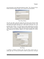
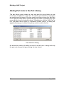
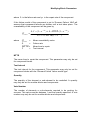
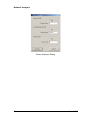
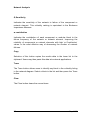
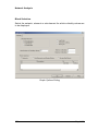
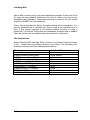
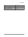
Project Options Project Options – Precision Tab The Precisions Tab allows the user to specify a precision value of 2, 3, 4, 6 or 9 and a format type of automatic or exponent. The precision value determines the number of significant figures displayed in calculated floating point numbers. Selection of the automatic format will result in floating point numbers being displayed either in standard numerical format or as a number followed by an exponent. The format chosen by the program will depend on the absolute value of the individual floating point number. If the exponent option is chosen then floating point numbers will be followed by an exponent unless the exponent value is zero. Consider the floating point number 0.001234567 The table below illustrates how the number will be displayed for a variety of format and precision combinations. Format Automatic Automatic Exponent Exponent NAP V1.0 Precision 6 3 6 3 Displayed Number 0.00123457 0.00123 1.234567e-3 1.234e-3 69 Project Options Project Options – Colour Tab Default Component Block Colour The default background colour to be assigned to component blocks (blocks with no structure below them) as they are placed in the block diagram. Default Element Block Colour The default background colour to be assigned to element blocks (blocks with structure below them) as they are placed in the block diagram. Trace Colour The colour to be assigned to blocks that are included in the current criticality, cut or path set trace analysis. Users may trace an individual cut or path set in the network diagram be selecting the Trace button after selecting the set in the Results Dialog. Users may also trace an individual block in a criticality analysis by selecting the Trace button in the Results Dialog. 70 Nap V1.0 Project Options Project Options – Libraries Tab Check Attached Library Files for Changes If this option is selected NAP will check to see if attached library files have changed every time a project is opened. If a library has changed then the user will receive a message from NAP asking if the new library data is to be attached. Folders for Library Searches Users may define up to 6 folders that contain library files. If NAP cannot find a library file (using its full path name) when appending network data, or updating local library data, NAP will search the specified folders for the library. NAP V1.0 71 Modifying the Network Diagram 15. Modifying the Network Diagram Network Diagram Scaling Options A newly created network diagram is displayed at a default size. There are several options available for altering the size of an individual page of the diagram. They are all accessed via the ‘View’ pull-down menu. The ‘Zoom In’ and ‘Zoom Out’ menu options increase and decrease the size of the visible diagram page respectively by fixed scaling factors. The scaling factor can be set directly by the user through the use of the ‘Set Scale’ menu option. The ‘Full Page’ menu option scales the diagram so that it fits the display area. Any of these scaling options can be reset to the original default scale by choosing the ‘Reset Scale’ to Default menu option. Individual blocks and labels in a network diagram may also be scaled. Select the block or label and then move the mouse cursor over one of the 8 black handles surrounding the object. The mouse pointer cursor will change to a scale cursor. Hold the left mouse button down over one of the scale handles and move the mouse cursor to resize the object. Release the mouse button to redraw the object. NAP V1.0 73 Modifying the Network Diagram Moving Network Diagram Objects The position of blocks, nodes and labels in a network diagram can be modified after the initial positioning during their creation. Any connections in the diagram will be modified to account for the changing position of end point blocks or nodes. The first method of moving the objects is to select an object or group of objects and then use the mouse to drag the object to a new position. When an object is selected, it is surrounded by a highlight border that can be used to drag the object around the drawing area. When the cursor is moved over the border it changes to the familiar 'drag' cursor. If the left button is then pressed down the highlight border will move around with the cursor. When the left button is released the object will move to the new position. The second method of moving objects is to use the options on the ‘Shift’ menu or their equivalent accelerator keys. These options move the selected object or group of objects by a fixed amount. The amount can be one of two values depending on the setting of the ‘Small Shift’ menu option. 74 Nap V1.0 Modifying the Network Diagram Copying Network Diagram Objects The 'cut' and 'copy' facilities both transfer selected diagram objects to the clipboard. The cut facility also removes the objects from the current diagram. There are two distinct 'paste' facilities. The standard facility makes an exact copy of the clipboard contents whilst 'paste special' copies the structure below system blocks and creates unique reference IDs for the copied objects. These features can be accessed from the ‘Edit’ menu, the toolbar or the equivalent accelerator. NAP V1.0 75 The Grid Control 16. The Grid Control Using the Grid Control The grid control may be revealed by selecting the ‘Tables’ tab. The grid control displays data in a tabular format. categories may be displayed in the grid control: • • • • The following data Part Library Components Block Library Bitmap Library Selection of the appropriate tab below the grid control will display the required data category. If the tab that you require is not visible use the arrows to the left of the tabs to bring the appropriate one into view. Grid Control Displaying Part Library Data NAP V1.0 77 The Grid Control The grid control provides an alternative method of editing data. To modify a data item associated with a record in the list simply select the field with the left mouse button and then type in the data or select an option from a list. Use the tab and arrow keys to move from one field to another. When you have finished entering data click the left mouse button with the cursor outside the grid control. Pressing the Escape key aborts the current edit operation. You may also edit data by double-clicking the left mouse button with the cursor positioned over the grey button to the left of the grid row. Some columns may be disabled due to the type of data they are displaying. You may customise the layout of the grid control by pressing the right mouse button over the grid control and then selecting the appropriate option. Filter A dialog will appear allowing the Grid data to be filtered. Clear Filter Clears the Filter and shows all data in the chosen category. Find and Replace A dialog will appear allowing the user to replace one piece of text with another throughout the grid control. Grid Options A dialog will appear allowing the user to hide or reposition different fields. Wrap Text This option wraps the text in each grid cell where the text length exceeds the column width. Add New Item to Table Adds a new line to the bottom of the table 78 Nap V1.0 The Grid Control Undo Removes the last change made. Delete Deletes the highlighted row. NAP V1.0 79 The Grid Control Grid Control - Filter The Filter pop-up allows users to selectively filter the data shown in the grid control. Table Defines the category currently displayed that the filter will be applied to. Column Choose from the drop down box the column the filter is to be applied to. In the next drop down box choose the type of comparison to be made, for example, ‘equals’. Value The value or text that the comparison applies to. If a second comparison is required, choose either OR or AND from the next drop-down box and fill out the second comparison type and value. Filter by tree control selection Checking on this option shows only the data associated with the highlighted item in the tree control. Clicking Apply will immediately apply the chosen filter. Clicking OK applies the chosen filter and exits the dialog box. Clicking cancel exits the dialog without applying the chosen filter. 80 Nap V1.0 The Grid Control Filter Dialog NAP V1.0 81 The Grid Control Grid Control – Grid Options The Grid Option pop-up allows users to modify the position and visibility of fields. Visible Fields Shows the currently visible fields for the selected category. The order of the list is the order the fields are displayed in the grid. To change this order highlight the field using the left mouse button and click the Up or Down button to shift the highlighted item one place. To transfer fields to the Hidden list, highlight the item using the left mouse button and click on the right hand arrow. Hidden Fields Shows the currently hidden fields for the selected category. To transfer fields to the Visible fields list, highlight the item using the left mouse button and click on the left hand arrow. Field Layout and Visibility to Default To reset the Grid layout to the default settings click the Field Layout and Visibility to Default button. Clicking the OK button will exit the Grid Option pop-up making the requested changes to the Grid. Clicking the Cancel button will exit the Grid Option pop-up without making the requested changes. 82 Nap V1.0 The Grid Control Grid Control – Find and Replace This dialog allows strings of text to be replaced with alternative strings of text throughout a column of data. Table Defines the category currently displayed that the filter will be applied to. Column Choose from the drop down box the column the text change is to be applied to. Find what The text to be found and replaced. Replace with The new text to be entered in place of the existing defined text. Match case Indicates that only text matching the case of that defined will be found. Match entire cell Indicates that the entire cell must match the text to be found. NAP V1.0 83 The Grid Control Grid Options Dialog 84 Nap V1.0 Network Analysis 17. Network Analysis Performing an Analysis Before commencing an analysis ensure that the required analysis options are specified in the Project Options Dialog. The analysis procedure may be initiated by selecting the ‘Analysis, Start’ pull-down menu option or equivalent toolbar button. The program will perform the following operations. • • • • • Check the network diagram for logical errors Generate the source to target paths for the networks defined in the project Generate the minimal cut sets for the networks defined in the project Quantify network availability and reliability parameters Determine criticality rankings If any fatal errors are encountered when checking the project data the analysis will be aborted and the errors displayed to the user. During the analysis the program will indicate which operations are being performed via the message area at the bottom of the principal window. The path determination and minimal cut set evaluation processes are often the most time consuming part of an analysis. During the path determination and minimal cut set generation you may temporarily halt the analysis by selecting the ‘Analysis, Pause’ pull-down menu option or equivalent toolbar button. A dialog will appear allowing you to increase the unavailability cut-off value and decrease the order and path cut-offs. The analysis may then be restarted. Alternatively, you may abort the analysis. When an analysis is successfully completed the analysis results are said to be up-to-date. Subsequent modifications to the project data may render the results out of date. NAP V1.0 85 Network Analysis Analysis Methods Component Revealed Failure Model This model is used to represent components whose failures are immediately revealed and assumes exponential distributions for both the failure and repair processes. The unavailability and failure frequency of a component represented by the revealed failure model are given by Q (t ) = λ λ+µ ω ( t ) = λ (1 − Q( t )) Component Dormant Failure Model Components which form part of a protection or standby arrangement may not have their failures revealed until they are required to operate or until a scheduled maintenance task or test takes place. Only at these times can repairs be performed. In effect dormant components exhibit characteristics similar to nonrepairable components during periods between tests. The actual variation of unavailability with time is periodic in nature. 86 Nap V1.0 Network Analysis Q versus t plot for the dormant failure model with t << MTTF The NAP dormant failure model determines mean unavailability and failure frequency values over the test interval. In effect the model takes a mean value of the saw toothed behaviour of the component unavailability illustrated above. The expression for determining mean unavailability is given below. Qmean where λ .τ − (1 − e − λτ ) + λ . MTTR.(1 − e − λτ ) = λ .τ + λ . MTTR(1 − e − λτ ) Qmean = λ = MTTR = = τ Mean unavailability value Failure rate Mean time to repair Test interval This expression simplifies to an approximate representation in the case where λτ << 1 and λ . MTTR << 1 : Qmean = NAP V1.0 λ .τ + λ . MTTR 2 87 Network Analysis The failure frequency is given by the expression ω mean = λ (1 − Qmean ) System Parameters This section describes the procedures used by the program to evaluate the minimal cut sets and the methods for calculating the standard system quantitative parameters. Cut set occurrence probabilities and failure frequencies are determined from the following expressions. Qcut = ∏i =1 Qi n where Qi Qcut n = the unavailability of the ith component in the cut set = the cut set occurrence probability = number of components in the cut set ω cut = ∑ j =1 ω j ∏i =1 Qi n n i≠ j where ωj = failure frequency of the jth component in the cut set ω cut = cut set occurrence frequency System unavailability values are calculated by applying the EsaryProschan expression Qnet = ∏i =1 Qi [1 − ∏ j =1 (1 − Qcutj )] m where 88 Qi m n = unavailability of common component i = number of common components occurring in all cut sets Nap V1.0 Network Analysis Qcutj n Qnet = unavailability of cut set j excluding common components = number of cut sets = network unavailability Network failure frequencies are calculated by applying the expression ω net = ∑i =1 ω cuti ∏ j =1 (1 − Qcutj ) n n j ≠i where ω cuti Qcutj ω net = failure frequency of cut set i = unavailability of cut set j = network failure frequency Note that these expressions provide upper bound approximations to the exact values for the network unavailability and failure frequency. Other network parameters are calculated from the following expressions Anet = 1 − Qnet where Qnet Anet = network unavailability = network availability TDTnet = Qnet .T where Qnet T TDTnet NAP V1.0 = network unavailability = time span for network reliability calculations = total network down time 89 Network Analysis Wnet = ω net .T where ω net Wnet = network failure frequency = no of expected network failures over time span λnet = where ω net Qnet λnet ω net 1 − Qnet = network failure frequency = network unavailability = network conditional failure intensity (CFI) Fnet = 1 − e − λnetT where T λnet Fnet = time span for network reliability calculations = network conditional failure intensity (CFI) = network unreliability over time span Rnet = 1 − Fnet where Fnet Rnet = network unreliability over time span = network reliability over time span MTTFnet = where 90 λnet MTTFnet 1 λnet = network conditional failure intensity (CFI) = mean time to first network failure Nap V1.0 Network Analysis MTTRnet = where Qnet Anet λnet MTTRnet Qnet λnet . Anet = network unavailability = network availability = network conditional failure intensity (CFI) = mean time to repair the network MTBFnet = MTTFnet + MTTRnet where MTTFnet MTTRnet MTBFnet NAP V1.0 = mean time to first network failure = mean time to repair the network = mean time between network failures 91 Network Analysis Data Verification Before an analysis is performed, NAP automatically checks the network models for errors. If a fatal error is found (preventing the analysis from proceeding) NAP will reveal the Data Verification Dialog listing the errors. Users may locate and edit the associated object by selecting the error message and then selecting the ‘Edit’ or ‘Find’ buttons in the dialog. The following verification checks are made by NAP. Source and Target Nodes Users must set one source and one target node for each network in the top level network diagram. Source and target nodes are set in the Node Dialog. Users may not set more than one source or target node for an individual network in the top level. However, users may set single source and target nodes for sub-networks below the top level network diagram. Sockets Blocks and nodes defined as socket blocks must not be defined below other socket blocks. Single Source and Target for Simple Blocks Simple blocks (blocks with no connection sockets defined below them) must have a single implied source and target block or node. That is, there must be only one route in and one route out of the diagram. Valid Switching Delays Switching delays may only be specified for nodes in simple blocks connected to component blocks or super blocks containing no common blocks. 92 Nap V1.0 Network Analysis The Pause Analysis Dialog The Pause Analysis Dialog appears if you select the ‘Analysis, Pause’ pull-down menu option or equivalent toolbar button. It allows you to abort the current analysis or modify the cut-off values to speed up the analysis. Unavailability Cut-Off If the unavailability cut-off is set on the program will determine which minimal cut sets are discarded during an analysis due to the occurrence probability of the cut set. It is advisable to apply an unavailability cut-off rather than an order cut-off as high order cut sets cannot be guaranteed to have a low occurrence probability. Order Cut-Off The order cut-off, when set on, will determine which minimal cut sets are discarded during an analysis due to the number of events occurring within the cut set. For example, a minimal cut set consisting of 5 basic events will be discarded if the order cut-off is set at 4, but not if the order cut-off is set at 5. Path Cut-Off The path cut-off, when set on, will determine which paths are discarded during an analysis due to the number of network elements being traversed by a path (number of hop counts). For example, a path traversing 10 network elements will be discarded if the ‘hop count’ is set at 9, but not if the ‘hop count’ is set at 10. NAP V1.0 93 Network Analysis Pause Analysis Dialog 94 Nap V1.0 Network Analysis The Results Dialog The Results Dialog displays summary, criticality and cut set information for networks, elements and sub-elements. Select the appropriate tab and button to display the appropriate data. Summary Results Unavailability The probability that the network or network element will be unavailable. Availability The probability that the network or network element will be available. Failure Frequency The number of failures of the network or network element per unit time. CFI The number of failures of the network or network element between time t and t + dt given that the network or network element was operating at time t. MTTF The mean time to failure of the network or network element. MTTR The mean time to repair the network or network element. NAP V1.0 95 Network Analysis MTBF The mean time between failures for the network or network element. Unreliability The probability that the network or network element has failed one or more times up to the ‘Reliability Time Span’ specified by the user in the Analysis tab of the Project Options Dialog. Reliability The probability that the network or network element has survived up to the ‘Reliability Time Span’ specified by the user in the Analysis tab of the Project Options Dialog. Total Down Time The expected total down time of the network or network element over the ‘Reliability Time Span’ specified by the user in the Analysis tab of the Project Options Dialog. Copy Selection of this button copies the results data in the lower list to the clipboard. Users may then paste this data into external applications. 96 Nap V1.0 Network Analysis Summary Results Dialog Criticality Rankings Q Contribution Indicates the contribution of each component or modular block to the unavailability of the network or network element. This criticality ranking is equivalent to the Fussell-Vesely Importance Measure. Improving the reliability of components or network elements with high ‘Q Contribution’ values is the most effective way of increasing network availability. NAP V1.0 97 Network Analysis Q Sensitivity Indicates the sensitivity of the network to failure of the component or network element. This criticality ranking is equivalent to the Birnbaum Importance Measure. w contribution Indicates the contribution of each component or modular block to the failure frequency of the network or network element. Improving the reliability of components or network elements with high ‘w Contribution’ values is the most effective way of decreasing the number of network failures. Copy Selection of this button copies the results data in the lower list to the clipboard. Users may then paste this data into external applications. Trace The Trace button allows users to identify any block in the criticality listing in the network diagram. Select a block in the list and then press the Trace button. Clear The Clear button clears the current trace. 98 Nap V1.0 Network Analysis Criticality Results Dialog Cut Sets Cut sets are minimal combinations of component or network element failures that will result in the failure of the network. A maximum of 1000 cut sets are displayed in the results summary dialog. Filter Users may filter the cut sets displayed in the dialog by typing the reference ID of one or more blocks in the filter field. Separate the names of multiple blocks with commas. NAP will display all cut sets containing all the named blocks. NAP V1.0 99 Network Analysis Copy Selection of this button copies the results data in the lower list to the clipboard. Users may then paste this data into external applications. Trace The Trace button allows users to identify the blocks within a cut set in the network diagram. Select a cut set in the list and then press the Trace button. Clear The Clear button clears the current trace. Cut Sets Results Dialog 100 Nap V1.0 Network Analysis Path Sets Path sets are the minimal paths through the network or network element that will ensure success of the network. A maximum of 1000 paths are displayed in the results summary dialog. Filter Users may filter the path sets displayed in the dialog by typing the reference ID of one or more blocks in the filter field. Separate the names of multiple blocks with commas. NAP will display all paths containing all the named blocks. Copy Selection of this button copies the results data in the lower list to the clipboard. Users may then paste this data into external applications. Trace The Trace button allows users to visually trace a path set in the network diagram. Select a path set in the list and then press the Trace button. Clear The Clear button clears the current trace. NAP V1.0 101 Network Analysis Paths Results Dialog 102 Nap V1.0 Network Analysis Results Graphs Results graphs are displayed when the user selects the ‘Results’ tab above the right-hand NAP window. Graphs are provided for criticality values. Graph options may be modified by selecting the ‘View, Graph Options’ pull-down menu option or equivalent toolbar button. The Graph Options Dialog will appear allowing the user to modify the following settings. Criticality Measure The criticality measure to be displayed. Log Scale Indicates a log scale is to be used if checked. Automatic Scaling Indicates that minimum and maximum scale values are to be automatically if checked. Show Grid A background grid will be displayed if checked. Max. Number of Criticality Values The maximum number of criticality values to be displayed. NAP will display the blocks with the highest criticality values. Minimum Criticality The minimum scale value for the graph. Maximum Criticality The maximum scale value for the graph. NAP V1.0 103 Network Analysis Block Selection Select the network, element or sub-element for which criticality values are to be displayed. Graph Options Dialog 104 Nap V1.0 Reports 18. Reports You can print, preview and design reports or graphs by selecting the appropriate options on the NAP ‘File’ menu. All the reporting and graphing functions provided with the NAP are in fact handled by a separate program known as the Report Generator. The Report Generator is a generic facility that also provides the reporting functionality for other reliability applications. The Report Generator is a very powerful and flexible tool that allows you to design your own customised text reports and graphs as well as selecting standard reports provided with the application. When you select one of the Print, Print Preview or Design Report options on the NAP File menu NAP will copy the current project data (including simulation results) into an application database and start up the Report Generator. When the Report Generator starts up it will access the data contained in the database. The Report Generator may operate in a number of different configurations. For example, it may operate in a configuration suitable for designing new reports or modifying existing reports or it may operate in a configuration suitable for previewing reports. When NAP starts up the Report Generator (after the user has selected the Print, Print Preview or Design Report options on the NAP File menu) the Report Generator main window will appear. The initial configuration of the Report Generator will depend on which option was chosen from within NAP. The Report Generator has its own menu options and toolbar buttons and provides its own help facility. NAP also provides a Report Wizard that allows you to quickly create new reports from scratch. The Report Wizard may be accessed from the File menu. The Report Generator provides a wealth of options for printing, previewing and designing reports. A full description of these facilities may be obtained by accessing the Report Generator Help Facility or the Report Generator User Manual. NAP V1.0 105 Importing and Exporting Data 19. Importing and Exporting Data A powerful import/export facility is provided with NAP allowing data to be transferred directly to and from Microsoft Access databases and spreadsheet programs such as Microsoft Excel. In addition text files may be imported and exported. To access the import/export facility select the ‘File, Import’ or ‘File, Export’ pull-down menu options. The import/export function provides its own help facility. Further information on importing and exporting can be obtained in the Report Generator, Import Export User Manual. NAP V1.0 107 Database Structure 20. Database Structure You will need to refer to the NAP database structure if you are creating customised reports using the Report Generator or are using the Import and Export Programs. Note that some tables and fields are import disabled. NAP V1.0 109 Database Structure Blocks Table Import disabled fields are shown in italics. Field Name Option names/Comments ID Description Reference ID Shelf Name Slot Name Part Network Element Library Block Path Logic MTTR Cable Length Quantity Vote Simple Q w Failure Model Test Interval Block Group Component CCF Block CCF Part Block Notes Max. 32 characters Max. 120 characters Max. 32 characters Max. 32 characters Max. 32 characters Max. 32 characters Yes/No Yes/No Yes/No Probabilistic/Open/Closed 110 Unavailability Failure frequency Revealed Failure/Dormant Failure Yes/No Yes/No Yes/No Max. 255 characters Nap V1.0 Database Structure Part Groups Table Import disabled fields are shown in italics. Field Name Option names/Comments ID Library Description Type Parent Maximum 32 characters Library Name Maximum 120 characters Category/List Parent group NAP V1.0 111 Database Structure Parts Table Import disabled fields are shown in italics. Field Name Option names/Comments ID Vendor Library Description Type Part Group Component Failure Data Format Component Failure Rate Component MTTF Component Q Component w Cable Cut Rate Notes Maximum 32 characters Maximum 32 characters Library Name Maximum 120 characters <Unspecified>/Card/Cable/Shelf 112 Failure Rate/MTTF/w and Q Max. 255 characters Nap V1.0 Database Structure Project Options Table Import disabled fields are shown in italics. Field Name Option names/Comments Description Project File Frequency Unit Time Unit Cable Cut Rate Unit MTTR Unit Cable Length Unit Switching Delay Unit Order Cut-Off On Q Cut-Off On Path Cut-Off On Order Cut-Off Q Cut-Off Hop Count Criticality/Sets ID Program Version Maximum 120 characters NAP V1.0 Yes/No Yes/No Yes/No ID for criticality and cut sets tables 113 Database Structure Criticality Table Import disabled fields are shown in italics. Field Name Option names/Comments Block ID Block Description Q Contribution Q Sensitivity w Contribution 114 Nap V1.0 Database Structure Cut Sets Table Import disabled fields are shown in italics. Field Name Option names/Comments Cut Set Q w Order Unavailability Failure Frequency Number of blocks in the cut set NAP V1.0 115 Database Structure Paths Table Import disabled fields are shown in italics. Field Name Option names/Comments Path Hop Count Number of network elements in path 116 Nap V1.0 Database Structure Results Table Import disabled fields are shown in italics. Field Name ID Description Q w CFI A R F MTTF MTTR MTBF TDT Level Block NAP V1.0 Option names/Comments Unavailability Failure Frequency Conditional Failure Intensity Availability Reliability Unreliability Mean Time to Failure Mean Time to Repair Mean Time Between Failure Total Down Time Network/Simple Block/Simple Sub- 117 Installing NAP 21. Installing NAP Installation Introduction These instructions apply to the Windows 95/98/Me, NT, Xp and 2000 operating systems. The installation instructions are categorised by installation type standalone, network server or network client. At the end of each installation type section are notes for each particular operating system/server type (where appropriate). Before starting the installation please ensure : that all other processes on the target machine have been terminated. that you are logged in as the system administrator. that you have full access to the installation (usually Program Files) directory on the target machine (and read/write access to the server for network client installations). that you read the notes appropriate to your operating system/server type at the end of each installation type section. File permissions are discussed more fully under each installation type. Note that the installation process takes a ‘conservative’ approach to updating system DLLs and ActiveX controls. These components will only be updated if the component version number contained in the CD-ROM installation is greater than that of the component on the target machine. To start the installation insert the CD in the CD-ROM drive. Normally the installation will start automatically. If this is not the case then select Run from the Windows Start menu and then Browse. Now navigate to the CDROM drive, open the disk1 folder and select the Setup.exe program. Select OK on the Run dialog to start the installation. Now refer to the standalone installation instructions if you have a licence to install NAP on a single machine. Refer to the network server installation type if you have a licence to install NAP on a network server. NAP V1.0 119 Installing NAP Refer to the network client installation type if you have already installed NAP on your network server and are now installing to a client. At the end of the standalone and network server installations you will be presented with detailed instructions on how to obtain your NAP license. Please ensure that you read and understand this information fully. If you are installing a standalone or network server version then you must refer to the Appendix ‘FLEXNET License Server’ for instructions on how to apply for, and install, your license. Note that the program will not run until you have installed the license. At the end of the installation process a readme file will be displayed; this contains the FLEXNET hostid for your machine. Please read this file and attach it to the e-mail you send to request your license. If you are installing NAP in a network server/client configuration please install the network server copy of NAP first and obtain the licence for this copy before installing the network client(s). 120 Nap V1.0 Installing NAP Installing on a Standalone Machine After starting the installation process : The Welcome dialog is displayed initially, select Next to display the Select Setup Type dialog. Select the Standalone option from the list and then select Next to display the Choose Destination Folder dialog. Select the folder (directory) in which you wish to install NAP. This is the top-level directory of the installation and is normally C:\Program Files, although any directory may be chosen. This folder must be on a local hard disk drive of the machine on which you are installing. Select Next to display the Select Program Folder dialog. Enter the program folder name. This is NAP by default, although any name may be chosen. A shortcut to the NAP program will be created in this folder. Select Next to display the Select Shortcut Options dialog. By default, additional desktop and start menu shortcuts to the NAP program are created. To prevent these being created de-select the check boxes. Select Next to display the Select Default Paper Size dialog. Select either ISO A4 or US Letter as the default paper size for your reports. Select Next to display the FLEXNET Server Hostid dialog. This dialog displays the FLEXNET hostid for your machine. You will send this hostid to Isograph in order to receive your license. Detailed instructions on obtaining your license are displayed at the end of the installation process. This hostid is unique to the machine you have installed on. Select Next to display the Start Copying Files dialog. NB: If you already have NAP installed on your machine you will be asked if you wish to overwrite your Report Generator, Import and Export databases. These contain your reports, import and export templates respectively. If you choose to overwrite your report database then your old report formats are still accessible via the new Alternate Report Database option in the Report Explorer. The old report database will be saved as MV5NpR.rkz. NAP V1.0 121 Installing NAP Select Next to start the file copy and registration process. At the end of the file copy process detailed instructions on how to obtain your license are displayed using Notepad. These instructions are saved in the file <install directory>\RAMS\License\readme.txt. When this is finished the Setup Complete dialog will be displayed. You may be prompted as to whether you wish to reboot the machine now or later. If this prompt appears it is because another process is using a shared DLL or ActiveX control that the installation program tried to update. The new version will be installed when the machine is rebooted. File Permissions Ensure that the NAP user has Read, Execute, List Folder Contents access to the <install directory>\Rams directory and below. The following subdirectories should have the additional permissions: Directory Additional Permissions RAMS\Common\Dictnry\User RAMS\Common\Export\Data RAMS\Common\Import\Data RAMS\Common\RepGen\Data RAMS\Export\?.?\Program RAMS\Import\?.?\Program RAMS\RepGen\?.?\Program RAMS\Nap\?.?\Examples RAMS\Nap\?.?\Program Write, Modify Write Write Write Write Write Write Write, Modify Write 122 Nap V1.0 Installing NAP Installing on a Network Server After starting the installation process : The Welcome dialog is displayed initially, select Next to display the Select Setup Type dialog. Select the Network Server (Microsoft Windows) or Network Server (Novell Netware) option from the list according to your server type and then select Next to display the Choose Destination Folder dialog. Select the folder (directory) in which you wish to install NAP. This is the top-level directory of the installation and is normally C:\Program Files, although any directory may be chosen. This folder must be on a local hard disk drive of the machine you are installing on. Select Next to display the Select Program Folder dialog. Enter the program folder name. This is NAP by default, although any name may be chosen. A shortcut to the NAP program will be created in this folder. Select Next to display the Select Shortcut Options dialog. By default additional desktop and start menu shortcuts to the NAP program are created. To prevent these being created de-select the check boxes. Select Next to display the Select Default Paper Size dialog. Select either ISO A4 or US Letter as the default paper size for your reports. Select Next to display the FLEXNET Server Hostid dialog. This dialog displays the FLEXNET hostid for your machine. You will send this hostid to Isograph in order to receive your license. Detailed instructions on obtaining your license are displayed at the end of the installation process. This hostid is unique to the machine you have installed on. Select Next to display the FLEXNET Server Location dialog. Enter the hostname or IP address of the machine where the FLEXNET license server will be running. In the present case of a network server installation this will normally be the machine where the installation is being performed. It is only necessary to enter this value if you intend to run the software on the network server. If a non-default port is being used for the license server select the No button and enter the port number (see the Appendix ‘FLEXNET License Server’ for more details on this). These values enable NAP to communicate with the FLEXNET license server. Select Next to display the Start Copying Files dialog. NAP V1.0 123 Installing NAP NB: If you already have NAP Version 1.0 (or an earlier version of the program) installed on your machine you will be asked if you wish to overwrite your Report Generator, Import and Export databases. These contain your reports, import and export templates respectively. If you choose to overwrite your report database then your old report formats are still accessible via the new Alternate Report Database option in the Report Explorer. The old report database will be saved as MV5NpR.rkz. Select Next to start the file copy and registration process. At the end of the file copy process detailed instructions on how to obtain your license are displayed using Notepad. These instructions are saved in the file <install directory>\RAMS\License\readme.txt. When this is finished the Setup Complete dialog will be displayed. You may be prompted as to whether you wish to reboot the machine now or later. If this prompt appears it is because another process is using a shared DLL or ActiveX control that the installation program tried to update. The new version will be installed when the machine is rebooted. File Permissions Ensure that all NAP network users have Read, List Folder Contents, Execute access to the <install directory>\Rams directory and below. The following sub-directories should have the additional permissions: Directory Additional Permissions RAMS\Export\?.?\Program RAMS\Import\?.?\Program RAMS\RepGen\?.?\Program RAMS\Nap\?.?\Program Write Write Write Write For users running NAP on the network server set the file permissions as detailed in the section on standalone installation. Ensure that the Administrator group has Full Control permission on the License directory. 124 Nap V1.0 Installing NAP Installing on a Network Client Before installing a network client please ensure that you have shared either the <Install Directory> or <Install Directory>\RAMS on the network server. Ensure also that the user name you are using for installation of the network client has Full Control permissions on this share. After starting the installation process : The Welcome dialog is displayed initially, select Next to display the Select Setup Type dialog. Select the Network Client option from the list and then select Next to display the Choose Destination Folder on Network Client dialog . Select the folder (directory) in which you wish to install the NAP client files. This is the top-level directory of the installation and is either C:\Program Files or, more probably, in a network installation, the user’s home directory or sub-directory of the home directory, although any directory may be chosen. Report, import and export templates that the user creates will be stored inside this directory structure so ensure that this directory is part of your backup plan. Select Next to display the Choose Installation Folder on Network Server dialog. Select Browse to choose the folder (directory) on the network server which contains the NAP program executable. Note that either the <Install Directory> or <Install Directory>\RAMS must be shared on the network server. The shared directory on the server may be referenced on the client using a mapped drive letter or using a UNC path name (e.g. \\servername\sharename). To refresh the Directories tree when using UNC path names enter the \\servername\sharename in Path text box of the Choose Folder dialog and then select OK. Now select Browse again and you will be able to navigate and select a directory from the refreshed Directories tree. After selecting the directory containing the NAP program executable select Next to display the Select Program Folder dialog. Enter the program folder name. This is NAP by default, although any name may be chosen. A shortcut to the NAP program will be created in this folder. Select Next to display the Select Shortcut Options dialog. NAP V1.0 125 Installing NAP By default additional desktop and start menu shortcuts to the NAP program are created. To prevent these being created de-select the check boxes. Select Next to display the Select Default Paper Size dialog. Select either ISO A4 or US Letter as the default paper size for your reports. Select Next to display the FLEXNET Server Location dialog. Enter the hostname or IP address of the machine where the FLEXNET license server will be running. If a non-default port is being used for the license server select the No button and enter the port number (see the Appendix ‘FLEXNET License Server’ for more details on this). These values enable NAP to communicate with the FLEXNET license server. Select Next to display the Start Copying Files dialog. NB: If you already have NAP Version 1.0 installed on your machine you will be asked if you wish to overwrite your Report Generator, Import and Export databases. These contain your reports, import and export templates respectively. If you choose to overwrite your report database then your old report formats are still accessible via the new Alternate Report Database option in the Report Explorer. The old report database will be saved as MV5NpR.rkz. Select Next to start the file copy and registration process. When this is finished the Setup Complete dialog will be displayed. You may be prompted as to whether you wish to reboot the machine now or later. If this prompt appears it is because another process is using a shared DLL or ActiveX control that the installation program tried to update. The new version will be installed when the machine is rebooted. File Permissions Ensure that the NAP user has Read, Execute, List Folder Contents access to the <install directory>\Rams directory and below on the network client machine. The following sub-directories should have the additional permissions: 126 Nap V1.0 Installing NAP Directory Additional Permissions RAMS\Common\Dictnry\User RAMS\Common\Export\Data RAMS\Common\Import\Data RAMS\Common\RepGen\Data RAMS\Nap\?.?\Examples Write, Modify Write Write Write Write, Modify NAP V1.0 127 Licensing NAP 22. Licensing NAP FLEXNET License Server Introduction At the end of the standalone or network server installations you will be you will be presented with detailed instructions on how to obtain your NAP license. Please ensure that you read and understand this information fully. To receive your license you must e-mail the FLEXNET hostid, your company name, your site name, and which licenses you wish to activate, to the appropriate contact address for your region. The license you receive in return by e-mail will be a text file. You should only modify information in the text file where detailed by the instructions below. Please note that the text file contains one (or more) encrypted signatures preventing modification of the actual license details. After receiving you license you should: Refer to the section ‘Installing Standalone Licenses’ below if you have selected the standalone installation Refer to the section ‘Installing the FLEXNET License Server’ if you have selected the network server installation’ and have not previously licensed an Isograph product using FLEXNET. Refer to the section ‘Adding Licenses to an Existing FLEXNET License Server’ if you have selected the network server installation and this is an additional license. Refer to the section ‘Installing a Separate FLEXNET License Server’ if you have selected the network server installation and wish to install the FLEXNET server on a separate machine to the NAP network server installation. Refer to the section ‘The Select License dialog’ for information for end users on how to select which NAP module(s) they wish to use. Refer to the section ‘Monitoring FLEXNET Licenses’ for information on the use of LMTOOLS for checking on license status. NAP V1.0 129 Licensing NAP Installing Standalone FLEXNET Licenses Copy the license file to the <Installation Directory>\RAMS\License directory, ensuring that it has a different filename to any existing license files. Alternatively, you may, using a text editor such as Notepad, append the contents of the new license file to an existing license file. The license file you receive will be in the format: SERVER this_host hostid VENDOR isograph {License Details} The SERVER and VENDOR lines may be removed from the additional license if you are appending to an existing license file. 130 Nap V1.0 Licensing NAP Installing the FLEXNET License Server Installing the FLEXNET License File Copy the license file to the <Installation Directory>\RAMS\License directory. The license file you receive will be in the format: SERVER this_host hostid VENDOR isograph {License Details} You may edit the license file to specify the actual host name (or IP address), set the port number that the license server uses and set the port number that the vendor service (daemon) uses. The hostid must not be modified. For example: SERVER 168.192.0.200 hostid 8000 VENDOR isograph 8001 In this case the license server is running on 168.192.0.200, using port 8000 and the vendor service is using port 8001. Note that if any clients are connecting via a firewall then these ports must be opened for bi-directional communication. In the default installation it is not strictly necessary to specify the host name because the clients already have this information provided at installation time. However if you wish the clients to connect to the license server by specifying the directory path of the license file(s) (see the subsection ‘Modifying the Network Client FLEXNET Server Reference’) then it is necessary to set this_host to the host name (or IP address). Starting the FLEXNET License Server On the license server machine start the FLEXNET license server by selecting the Windows taskbar Start-Programs-NAP-FLEXNET License Server-LMTOOLS menu option. This displays the FLEXNET LMTOOLS application. Select the Config Services tab. NAP V1.0 131 Licensing NAP Now enter a name for the Service Name in the corresponding combo box. Typically enter Isograph. Next set the paths for the lmgrd.exe file, the license file and the path to the debug log file. These will be: <Install Directory>\RAMS\License\lmgrd.exe for lmgrd.exe. <Install Directory>\RAMS\License for the license file(s). Do not specify the license file otherwise any additional licenses added at a later date will not be served by the license server. <Install Directory>\RAMS\License\isograph.log for the debug log file Set both the Use Services and Start Server at Power Up check boxes to selected. Save the Isograph service by selecting Save Service. Now select the Start/Stop/Reread tab. Select Start Server to start the license server and the isograph service. This same tab may be used to stop the license server and to reread the license directory. Advanced configuration of the license server is described in the End User Guide (PDF format). This is accessed by selecting the Windows taskbar Start-Programs-NAP-FLEXNET License Server-End User Guide menu option. The FLEXNET command line utility lmutil.exe is contained in the <Install Directory>\RAMS\License directory. This utility is required to run many of the command line utilities referenced in the End User Guide. Modifying the Network Client FLEXNET Server Reference When a network client is installed the user is prompted to specify the location (and optionally the port number) of the FLEXNET license server. These values enable NAP to communicate with the FLEXNET license server. This value is stored in the registry string value: HKEY_LOCAL_MACHINE\Software\RAMS\NAP\LicenseServerLocation 132 Nap V1.0 Licensing NAP The format of the value is: @hostname (or IP address) or port number@hostname (or IP address) if a non-default port number has been specified. It may be necessary to change this value if the hostname or port number is modified on the license server. It is also possible to enter the path to the license server directory in place of the hostname and port number. If this option is chosen (perhaps for reasons of consistency with existing FLEXNET implementations) then the license file SERVER line must be modified to specify the hostname (or IP address). NAP V1.0 133 Licensing NAP Adding Licenses to an Existing FLEXNET License Server Copy the license file to the <Installation Directory>\RAMS\License directory on the network server, ensuring that it has a different filename to any existing license files. Alternatively, you may, using a text editor such as Notepad, append the contents of the new license file to an existing license file. See the section ‘Installing the FLEXNET License Server’ for details on modifying the hostname and the default port numbers. To inform the FLEXNET license server of the additional license(s) select the Windows taskbar Start-Programs-NAP-FLEXNET License ServerLMTOOLS menu option. This displays the FLEXNET LMTOOLS application. Select the Start/Stop/Reread tab. Select ReRead License File to register the new license(s) with the license server. 134 Nap V1.0 Licensing NAP Installing a Separate FLEXNET License Server Copy the <Install Directory>\RAMS\License directory to a directory on the required license server machine. Ensure that the Administrator group has Full Control permissions on this directory. Now follow the instructions in the section ‘Installing the FLEXNET license server’. NAP V1.0 135 Licensing NAP The FLEXNET ‘Select Licenses’ Dialog Checking Out a License To select the licenses to be ‘checked out’ select the appropriate check box in the Select column and then select OK. Borrowing a License Borrowing allows the user to ‘borrow’ selected module license(s) from the FLEXNET license server on to their own network client machine. This means that the client can then be disconnected from the network and NAP will still be licensed using the borrowed module license(s). When borrowing a license(s) the expiration date is specified and when this date is reached the license(s) are automatically returned to the FLEXNET license server. Whilst a license is borrowed the license count on the server will be reduced by one for the corresponding module. Please note that you will not be able to borrow licenses unless this option has been activated in the license issued to you by Isograph. To borrow a license(s) select Help-Licence to display the Select Licenses dialog (in the multiple module license case this is displayed automatically at program startup). Enter the expiry date for borrowing in the Until: text box. This must be in the format dd-mmm-yyyy (e.g. 30-Oct-2004). Now select Activate License Borrowing – you will be prompted that this action will turn on license borrowing for all future license check outs and that any currently checked out licenses will be checked back in. Select Yes to continue. Now select which license(s) you wish to check out and then select OK. The selected license(s) have now been borrowed on to your local machine. To return a borrowed license(s) early select Return Borrowed License(s). Displaying License Users and License Info To display the current users of all the licensed modules select Users – All Modules. This will display each of the licensed modules in turn along with the users who have currently checked out licenses for each of these modules. To display the current users of a selected module first select the required module in the list view and then select Users – Selected Module. 136 Nap V1.0 Licensing NAP Note that both these options use the term ‘Feature’ in their display. This is because although you are licensed by module in NAP the module licenses are implemented using FLEXNET ‘features’. So when describing a license issue to a FLEXNET license server administrator it is best to use the term ‘feature’ as a substitute for ‘module license’! To display the current NAP license file information select License Info. This simply displays the contents of the license file NAP V1.0 137 Licensing NAP Monitoring FLEXNET Licenses Using LMTOOLS LMTOOLS is only installed on server installations. LMTOOLS provides facilities for a license server administrator to display what license(s) are currently checked out and diagnose any license server problems. On the license server machine start the FLEXNET license server by selecting the Windows taskbar Start-Programs-NAP-FLEXNET License Server-LMTOOLS menu option. This displays the FLEXNET LMTOOLS application. Advanced configuration of the license server is described in the End User Guide (PDF format). This is accessed by selecting the Windows taskbar Start-Programs-NAP-FLEXNET License Server-End User Guide menu option. Server Status To display current checked out license(s) select the Server Status tab, enter the Individual Daemon as Isograph and then select Perform Status Enquiry. Server Diags To display license server diagnostics select the Server Diags tab, enter the Feature Name and then select Perform Diagnostics. 138 Nap V1.0 Index Index A adding blocks · 57, 59, 60 analysis · 85 auto backup · 62 availability · 89, 95 B block group · 27 blocks table · 110 C category group · 21 CFI · 90, 95 colour options · 70 common cause failure · 9 common cause failure group · 27 conditional failure intensity · 90, 95 control key · 9 copy diagram object · 75 criticality ranking · 97 criticality table · 114 cut diagram object · 75 cut rate · 24 cut set delimiter · 62 cut sets · 99 cut sets table · 115 NAP V1.0 139 Index D database structure · 109 default MTTR · 24 defaults · 63 delete key · 7 design reports · 105 dormant failure model · 86 E Esary-Proschan method · 88 exponent · 69 export facility · 107 F failure data format · 23 failure frequency · 24, 95 failure rate · 11, 23 filter · 78, 80, 99, 101 find · 78, 83 find menu · 57 floating point numbers · 69 G grid control · 77 grid options · 78 H halt the analysis · 85 hop count · 67 I import facility · 107 140 Nap V1.0 Index installation · 119 L left mouse button · 7 library options · 71 licensing · 129 list group · 21 M minimal cut set evaluation · 85 minimal cut sets · 88 move · 74 MTBF · 91, 96 MTTF · 11, 24, 90, 95 MTTR · 91, 95 N network · 30 network availability · 89 network diagram · 3 network element · 4 network element group · 27 network reliability · 90 network unavailability · 89 network unreliability · 90 new project · 52 no of expected network failures · 90 O occurrence probabilities · 88 open project · 52 options · 61 order cut-off · 67 ordering blocks · 60 ordering shelves · 59 NAP V1.0 141 Index ordering slots · 59 ordering sub-blocks · 60 P part · 23 part group · 21 part groups table · 111 part library · 23, 26 part list · 26 part number · 23 parts table · 112 paste diagram object · 75 path cut-off · 67 path sets · 101 paths table · 116 precision · 69 preview reports · 105 print reports · 105 project options table · 113 Q Q contribution criticality ranking · 97 Q sensitivity criticality ranking · 98 R recent projects · 52 reliability · 90, 96 replace · 78, 83 reports · 105 reset scale to default · 73 results · 95, 103 results table · 117 revealed failure model · 86 right mouse button · 9 142 Nap V1.0 Index S save project · 52 save project as · 52 scale · 73 shift · 74 shift key · 10 socket · 92 sorting · 67 sorting cut sets · 67 source node · 92 sub-network · 3 switching delays · 68 system lifetime · 89 system quantitative parameters · 88 T target node · 92 time span · 67 toolbar · 8 total down time · 96 total network down time · 89 trace · 70, 98, 100, 101 transfer page numbers · 62 tutorial · 11 U unavailability · 24, 89, 95 unavailability cut-off · 67 units · 65 unreliability · 90, 96 V vendor · 23 verification · 92 view options · 66 vote number · 47 NAP V1.0 143 Index W w contribution criticality ranking · 98 wrap text · 78 Z zoom in · 73 zoom out · 73 144 Nap V1.0