1
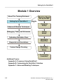
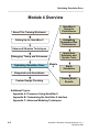
Advanced Modeling Techniques
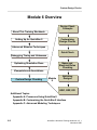
Appendix C Lessons
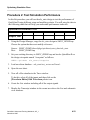
Creating QuickPart Table Models
QuickPart Table models are created by combining a functional logic table
description with a technology file of timing and constraint information. QuickPart
Table models provide the following advantages:
• Increased performance.
• Increased capacity. The compiled QuickPart Table model uses far less
memory that equivalent gate and behavioral models.
• Truth table format. This format is easy to create and support.
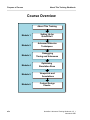
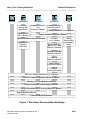
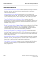
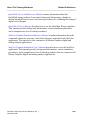
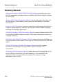
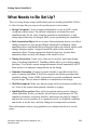
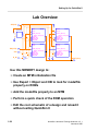
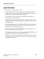
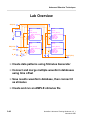
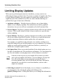
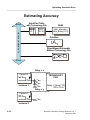
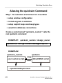
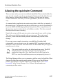
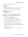
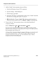
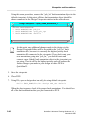
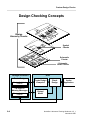
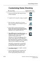
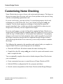
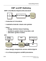
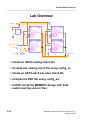
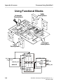
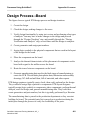
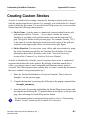
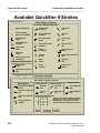
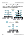
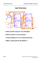
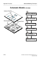
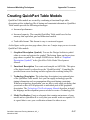
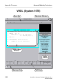
As the figure on the previous page shows, there are 3 major steps you use to create
QuickPart Table models:
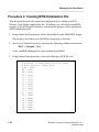
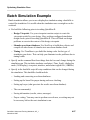
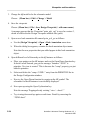
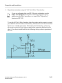
1. Graphical Description (Symbol). You use the Design Architect symbol
editor to create and register the symbol. The bottom figure on the previous
page shows a symbol for a simple NAND device. Refer to “Graphical
Description (Symbol)” in the QuickPart Table Model Development
Manual.
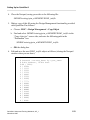
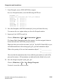
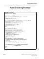
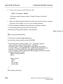
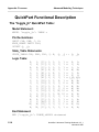
2. Functional Description. You create and compile an ASCII file. This piece
of the digital model is referred to as the “QuickPart table”. Compiling file
provides some error checking and also registers the resulting binary file.
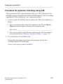
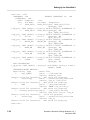
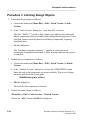
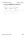
3. Technology Description. The technology description is an optional piece
of the QuickPart Table model. In it you can supply technology-specific
timing information such as propagation delays and timing constraints.
Without a technology description, you are able to only apply pin delays that
you attach as Rise or Fall properties to individual pins on the graphical
description. The Technology File Development Manual describes in detail
the language and development process needed to create a Technology File.
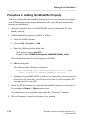
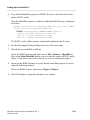
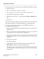
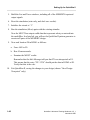
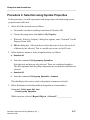
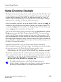
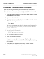
4. Model Verification. Create a schematic that contains an instance of your
model and use QuickSim II to verify that your model works as required. It
is a good idea to save your verification scheme for others to use.
QuickSim II Advanced Training Workbook, 8.5_1
November 1995
C-17