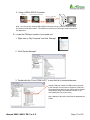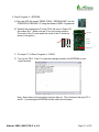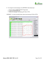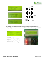
1
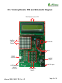
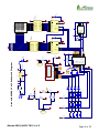
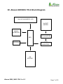
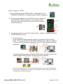
Getting Started with
ALEXAN ATMEL
AT89C2051/AT89C4051
Training Module - 2
Version 1.2
Copyright © 2007
Ace Electronic Technology Inc.
All Rights Reserved
Alexan 2051/4051 TM-2 v.1.2
Page 1 of 22
About This Guide
In this User’s Manual, it is assumed that the user is familiar with
microcontrollers on the following aspects:
1. How to program using an MCU programmer
2. MCU pin-outs and I/O port functions
3. How to use, program and control Alphanumeric LCD display (16x2), Dot
Matrix (8x8), Matrix Keypad (3x4), serial EEPROM, and serial port
communication
4. How to read and interpret a schematic diagram
5. Knowledge on some electronic terms and devices
It is also assumed that the user is familiar in microcontroller programming
either in C or assembly language. The user must have knowledge on
compiling/debugging source codes. Moreover, it is also assumed that the
user is knowledgeable on the standards and safety precautions in operating
electronic hardware including the correct handling of microcontrollers.
Alexan ATMEL AT89C2051/AT89C4051 Training Module-2 and Alexan
89CX051 TM-2 refers to the same module and will be used alternately.
Alexan 2051/4051 TM-2 v.1.2
Page 2 of 22
I. Overview
This user’s manual will guide you on how to use the ALEXAN 89CX051
Training Module-2 (TM-2). While the first training module, TM-1, covered
topics on LED lamps, 7-segments, buzzer, relay and serial communication,
this 2nd level training module has the following applications:
1. Alphanumeric LCD Display (16x2)
2. LED Dot Matrix (8x8)
3. Matrix Keypad (3x4)
4. Serial EEPROM
5. RS232 Serial Communication
The TM-2 is a helping tool in which you can explore the many features of a
microcontroller. Like TM-1, this module still uses ATMEL AT89C2051 and
AT89C4051 microcontroller (MCU).
You must first be familiar with and understand the schematic diagram of
the training module to facilitate your programming.
Alexan 2051/4051 TM-2 v.1.2
Page 3 of 22
II. Getting Started
What you need to get started
1. ALEXAN 89CX051 Training Module-2
2. 9V DC Power Adapter
3. ATMEL AT89C2051/AT89C4051 Microcontroller
4. 3-Pin Connector to Serial Connector for RS232
5. ATMEL Programmer
6. Debugger/Compiler for your source code
After writing your hex code into the microcontroller by means of an IC
programmer, insert your microcontroller into the 20-pin IC socket of your
training module.
Note: The notch of the IC socket must correspond to the notch of your
MCU. Incorrect placement might damage your MCU.
You may use the LCD display, dot matrix and matrix keypad at the same time.
However, the dot matrix and serial EEPROM may not be used at the same time as
the pins controlling the dot matrix and serial EEPROM (P1.0 and P1.1) are shared
by both components.
Alexan 2051/4051 TM-2 v.1.2
Page 4 of 22
III. Training Module PCB and Schematic Diagram
16x2 Alphanumeric LCD
8x8 Dot
Matrix
Display
EEPROM
MCU
RS232
Interface
LCD Backlight
On/Off
Connector
Alexan 2051/4051 TM-2 v.1.2
On/Off
Switch
9V DC Input
3x4 Keypad
Matrix
Page 5 of 22
PB
S6
PB
PB
S9
S3
S11
PB
S12
S2
S5
S8
10K
+5
10K
+5
3
2
1
RS232
JP1
PB
PB
PB
PB
B
Q2
+5
S1
S4
S7
S10
10K
+5
4K7
R22
4K7
R21
R19
4K7
9012
2
4K7
R18
R17
10K
1
3
2
9VDC SOCKET
J1
1
EC
3
PB
PB
PB
PB
Q3
9013
Rx
Tx
1
PWR SW
R20
4K7
+5
2
3
D1
+9
Vout
GND
LCM1
C1
220uF, 16V
22pF
22pF
Tx
Rx
1
2
3
1K
R1
15
16
EN
1
2
3
4
5
6
7
8
9
10
2K2
C5
10uF
.1uF
AT89C2051/4051
RST/VPP
VCC
P3.0
P1.7
P3.1
P1.6
XTAL2
P1.5
XTAL1
P1.4
P3.2
P1.3
P3.3
P1.2
P3.4 P1.1 (AIN)
P3.5 P1.0 (AIN)
GND
P3.7
MCU1
+5
1K
47, 1W
+9
DS1
LED
20
19
18
17
16
15
14
13
12
11
+5
+5
+9
+9
R/W
D7
D6
D5
D4
RS
LCD MODULE
A
K
LCM
Header 3H
P1
C2
10uF, 10V
D7
D6
D5
D4
Vin
+5
7805
D7
D6
D5
D4
D3
D2
D1
D0
14
13
12
11
10
9
8
7
VO
VDD
V SS
3
2
1
16
CL K
ST RO BE
3
1
VDD
DATA
2
S13
Alexan 89CX051 TM-2 Schematic Diagram
EN
R /W
RS
6
5
4
EN
R /W
RS
2
1
1K5
1K5
1K5
1K5
1K5
1K5
1K5
1K5
18
17
16
15
14
13
12
11
OUT1
OUT2
OUT3
OUT4
OUT5
OUT6
OUT7
OUT8
10
G N D CO M D
9
IN 1
IN 2
IN 3
IN 4
IN 5
IN 6
IN 7
IN 8
1
2
3
4
5
6
7
8
+5
15
+5
C3
.1uF
10K 10K
U3
+5
4094
U1
ULN2803A
8
7
6
5
+5
R1
R2
R3
R4
R5
R6
R7
R8
DS2Dot Matrix 8X8
24CXX
VCC
WP
SCL
SDA
U5
8
3
9
5
16
10
15
12
+9
.1uF
C6
A0
A1
A2
GND
1
2
3
4
16
CL K
ST RO BE
VDD
DATA
3
1
4
5
6
7
14
13
12
11
9
10
OE
C1
C2
C3
C4
C5
C6
C7
C8
2
Q1
Q2
Q3
Q4
Q5
Q6
Q7
Q8
QS
QS
GND
8
10
4
14
13
7
11
6
2
1
18
17
16
15
14
13
12
11
OUT1
OUT2
OUT3
OUT4
OUT5
OUT6
OUT7
OUT8
IN 1
IN 2
IN 3
IN 4
IN 5
IN 6
IN 7
IN 8
1
2
3
4
5
6
7
8
G N D CO M D
9
4
5
6
7
14
13
12
11
9
10
Q1
Q2
Q3
Q4
Q5
Q6
Q7
Q8
QS
QS
+5
GND
8
OE
15
Alexan 2051/4051 TM-2 v.1.2
Page 6 of 22
U4
4094
+5
U2
ULN2803A
C4
.1uF
IV. Alexan 89CX051 TM-2 Block Diagram
16x2 ALPHANUMERIC LCD
8x8 DOT
MATRIX
RS232
INTERFACE
OCTAL BUFFER
MCU
EEPROM
SHIFT
REGISTERS
3x4
KEYPAD
Alexan 2051/4051 TM-2 v.1.2
Page 7 of 22
V. Alexan TM-2 Pinouts
LCD
D0
D1
D2
D3
D4
D5
D6
D7
R/W
RS
ENABLE
SHIFT REGISTER
CLOCK
STROBE
DATA
EEPROM
CLOCK
DATA
RS232 INTERFACE
TRANSMIT
RECEIVE
KEYPAD
COLUMN 1
COLUMN 2
COLUMN 3
ROW 1
ROW 2
ROW 3
ROW 4
Alexan 2051/4051 TM-2 v.1.2
MCU PINOUTS
NOT CONNECTED
NOT CONNECTED
NOT CONNECTED
NOT CONNECTED
PORT 1.4
PORT 1.5
PORT 1.6
PORT 1.7
PORT 3.7
PORT 1.3
PORT 3.2
DESCRIPTION
DATA PIN
DATA PIN
DATA PIN
DATA PIN
DATA PIN
DATA PIN
DATA PIN
DATA PIN
READ/WRITE
COMMAND/DATA
ENABLE PIN
PORT 1.1
PORT 1.2
PORT 1.0
INPUT CLOCK
ENABLE PIN
DATA PIN
PORT 1.1
PORT 1.0
INPUT CLOCK
DATA PIN
PORT 3.1
PORT 3.0
TRANSMIT PIN
RECEIVE PIN
PORT
PORT
PORT
PORT
PORT
PORT
PORT
3.3
3.4
3.5
1.4
1.5
1.6
1.7
MATRIX COLUMN 1
MATRIX COLUMN 2
MATRIX COLUMN 3
MATRIX ROW1
MATRIX ROW2
MATRIX ROW3
MATRIX ROW 4
Page 8 of 22
VI. Operating Procedures for Demo Program
1. Demo Program 1 – DOT MATRIX
A. Burn the HEX file named “DEMO CODE – DOT MATRIX.HEX” into the
AT89C2051/AT89C4051 IC using the Alexan ATMEL Programmer.
B. Transfer the programmed IC to the TM-2. Be sure to Power Off
the module first. Make sure the IC is in the correct position.
The notch of the IC must match the notch of the IC socket as
shown in the picture.
LCD Display
8 9C X 0 51
Notch on
this side
Notch
IC Socket
Dot Matrix
IC
Matrix keypad
C. The letter “A” is displayed on the dot matrix. (Notice that the first line of the LCD
display will contain blocks, this shows that the LCD display has not been
initialized.)
Alexan 2051/4051 TM-2 v.1.2
Page 9 of 22
2. Demo Program 2 – LCD Display
A. Burn the HEX file named “DEMO CODE – LCD DISPLAY.HEX” into the
AT89C2051/AT89C4051 IC using the Alexan ATMEL Programmer.
8 9C X 0 51
B. Transfer the programmed IC to the TM-2. Be sure to Power Off
the module first. Make sure the IC is in the correct position.
The notch of the IC must match the notch of the IC socket as
shown in the picture.
Notch
IC Socket
IC
LCD Display
Notch on
this side
Dot Matrix
Matrix keypad
C. The message “WOW, IT’S A BLINKING MESSAGE” displays blinking on the LCD.
Alexan 2051/4051 TM-2 v.1.2
Page 10 of 22
3. Demo Program 3 – Matrix Keypad
A. Burn the HEX file named “DEMO CODE – KEYPAD.HEX” into the
AT89C2051/AT89C4051 IC using the Alexan ATMEL Programmer.
B. Transfer the programmed IC to the TM-2. Be sure to Power Off
the module first. Make sure the IC is in the correct position.
The notch of the IC must match the notch of the IC socket as
shown in the picture.
LCD Display
8 9C X 0 51
Notch on
this side
Notch
IC Socket
Dot Matrix
IC
Matrix keypad
C. Click a button on the matrix keypad and the corresponding digit for the button
displays on the LCD. For the sample below, the button S7 was clicked.
Alexan 2051/4051 TM-2 v.1.2
Page 11 of 22
4. Demo Program 4 – RS232
A. Burn the HEX file named “DEMO CODE – RS232.HEX” into the
AT89C2051/AT89C4051 IC using the Alexan ATMEL Programmer.
8 9C X 0 51
B. Transfer the programmed IC to the TM-2. Be sure to Power Off
the module first. Make sure the IC is in the correct position.
The notch of the IC must match the notch of the IC socket as
shown in the picture.
Notch
IC Socket
LCD Display
Notch on
this side
Dot Matrix
IC
Matrix keypad
C. Connect the serial port of your PC as shown below. (Steps C-F will also be used for
the EEPROM demo code.)
1. Direct Connection.
If your Personal Computer supports Serial Port, connect the TM-2 as shown
below. The 3-pin connector of TM-2 (labeled RS232) where each pin is labeled
2, 3 and 5 must be connected to the pins 2, 3 and 5 of your computer serial port
TM-1/TM-2
Back of PC: RS232 PORT
respectively.
1
6
2
3
9
5
You can use a 3-pin connector (Female), RS232 9-pin connector (Female), and
a MALE/FEMALE RS232 Cable to simplify the above connection.
TM-1/TM-2
RS232 CABLE
Back of PC: RS232 PORT
2
3
5
Internal connection of Rs232 CABLE
Note: You can leave pins 1, 4, 6, 7, 8 and 9 unconnected, they are not useful in our application
or you can also connect them, as long as they are connected 1-to-1(Pin 1 Male to Pin 1 Female,
Pin 4 Male to Pin 4 Female, and so on).
Alexan 2051/4051 TM-2 v.1.2
Page 12 of 22
2. Using a USB to RS232 Converter.
TM-1/TM-2
USB TO RS232 CONVERTER
Back of PC: USB PORT
Note: You can use any working USB to RS232 Converter, but you must first install the driver
and locate its COM port number. The COM port number of your serial port must be known for
this application.
D. Locate the COM port number of your serial port.
1. Right-click on “My Computer” and click “Manage”.
2. Click “Device Manager”.
3. Double-click the “Ports (COM & LPT)” to view the list of connected devices.
Sample COM port number for USB to serial converter.
In this example, the converter is located on COM port 1.
Take note that the driver of your USB to serial converter
automatically assigns the COM port number, so you
must identify the one you are using.
Note: Majority of the built-in serial port is designated as
COM1.
Alexan 2051/4051 TM-2 v.1.2
Page 13 of 22
F. To run the RS232 and EEPROM demo codes, the HyperTerminal program will be
used. HyperTerminal is included in the Windows Operating System.
1. Open HyperTerminal.
To open the HyperTerminal, click “Start > All Programs > Accessories >
Communications > HyperTerminal”
2. If prompted with the Location Information, click “Cancel”.
3. Click “Yes” to confirm.
4. Click “OK”.
5. In the Name box, type a name that describes your connection as shown in the
example below, then click “OK”.
Alexan 2051/4051 TM-2 v.1.2
Page 14 of 22
6. In the Connect To dialog box, choose the port number of your Serial Port or
USB to Serial converter using the drop down box to connect to TM-2.
7. In the COM Port Properties, set the following values listed below to set your
Port Settings and click “OK”.
Bits per second:
Data bits:
Parity:
Stop bits:
Flow Control:
9600
8
None
1
None
You have successfully loaded and configured the HyperTerminal!
Alexan 2051/4051 TM-2 v.1.2
Page 15 of 22
8. Configure the Hyper Terminal Properties. Under the File Tab,
choose Properties.
A Properties dialog box appears, choose the Settings tab, then
click the ASCII Setup button at the lower right portion of the box.
The ASCII Setup dialog box appears. Mark the following check boxes:
1. Send line ends with line feeds
2. Echo typed characters locally
3. Append line feeds to incoming line ends
4. Wrap lines that exceed terminal width
9. You may choose to save your new connection for easier access in the future.
From the File menu, choose Save. Enter your desired connection name.
G. Turn on the TM-2. A welcome message appears on your HyperTerminal. Whenever
you type a character from your keyboard, it would appear on TM-2's LCD screen.
Alexan 2051/4051 TM-2 v.1.2
Page 16 of 22
5. Demo Program 5 – EEPROM
A. Burn the HEX file named “DEMO CODE – EEPROM.HEX” into the
AT89C2051/AT89C4051 IC using the Alexan ATMEL Programmer.
8 9C X 0 51
B. Transfer the programmed IC to the TM-2. Be sure to Power Off
the module first. Make sure the IC is in the correct position.
The notch of the IC must match the notch of the IC socket as
shown in the picture.
Notch
IC Socket
LCD Display
Notch on
this side
Dot Matrix
IC
Matrix keypad
C. Do steps C-F of Demo Program 4 – RS232.
D. Turn on the TM-2. Click S1 to see the message stored in the EEPROM on your
HyperTerminal.
Note : Some dots on the dot matrix may also light up. This is because the pins (P1.0
and P1.1) controlling the EEPROM and dot matrix are the same.
Alexan 2051/4051 TM-2 v.1.2
Page 17 of 22
E. To change the saved message on the EEPROM, follow these steps:
1. Open the Alexan ATMEL 89CX051 Programmer.
2. Load the file EEPROM.HEX.
3. Modify the message code starting at 0114h to 01F3h.
WARNING: You can only modify those codes at code memory 0114h to 01F3h.
Alexan 2051/4051 TM-2 v.1.2
Page 18 of 22
6. Demo Program 6 – Dot Matrix, LCD Display, Matrix Keypad and EEPROM
A. Burn the HEX file named “DEMO CODE – TM2.HEX” into the
AT89C2051/AT89C4051 IC using the Alexan ATMEL Programmer.
B. Transfer the programmed IC to the TM-2. Be sure to Power Off
the module first. Make sure the IC is in the correct position.
The notch of the IC must match the notch of the IC socket as
shown in the picture.
LCD Display
8 9C X 0 51
Notch on
this side
Notch
IC Socket
Dot Matrix
IC
Matrix keypad
C. After turning on the TM-2, wait for two seconds. A welcome message will appear
on the LCD.
D. The main menu will appear shortly after the welcome message.
There are three (3) options, namely :
1. ReadEE
2. WriteEE
3. DM Scroll
S2 and S8 serves as the navigation keys. Press S2 to scroll up the menu.
Press S8 to scroll down the menu. Press S12 to confirm your selection
Note: The LCD that came with Alexan TM-2 does not have backlight functionality.
You may change the LCD to one that has backlight to make use of the backlight
function of the TM-2.
Alexan 2051/4051 TM-2 v.1.2
Page 19 of 22
Up
S1
S2
S3
S4
S5
S6
S7
S8
S9
S10
S11
S12
Down
Return
to Main
Menu
Confirm
Matrix Keypad Navigation Set-up
E. ReadEE – The last saved message on the EEPROM can be viewed on the LCD.
Press S2 to scroll up the message or press S8 to scroll down the message. Hold S11 to
return to the main menu.
NOTE: Due to the shared pins
controlling the dot matrix and serial
EEPROM, some dots on the dot
matrix may light up during serial
EEPROM reading and writing.
Alexan 2051/4051 TM-2 v.1.2
Page 20 of 22
F. WriteEE – Encode a message of up to 384 characters using the 3x4 matrix keypad
and store it in the serial EEPROM. The 3x4 matrix keypad functions like a mobile phone
keypad (refer to the character table). A cursor on the LCD screen appears. Hold S12 to
store the message into the serial EEPROM. Hold S11 to return to the main menu.
Character Table
S1:
S2:
S3:
S4:
S5:
S6:
S7:
S8:
S9:
S10:
S11:
S12:
.,-?!=+%1
ABC2
DEF3
GHI4
JKL5
MNO6
PQRS7
TUV8
WXYZ9
backspace
0 space
toggles character
case
Alexan 2051/4051 TM-2 v.1.2
S1
S2
S3
S4
S5
S6
S7
S8
S9
S10
S11
S12
3x4 Matrix Keypad
Page 21 of 22
G. DM Scroll – The message saved on the serial EEPROM will “scroll” on the dot matrix
display. To scroll the message again, press S12. To return to main menu, hold S11.
NOTE: The program scrolls any message saved in the serial EEPROM. Be sure to
write a message in the serial EEPROM before selecting the DM Scroll option. If no
message is stored in the EEPROM, then nothing will be displayed on the dot matrix.
The message on the lcd
scrolls (from right to left)
on the dot matrix
Alexan 2051/4051 TM-2 v.1.2
Page 22 of 22