1
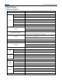
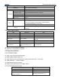
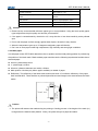
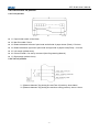
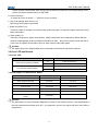
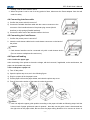
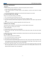
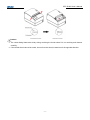
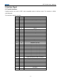
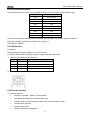
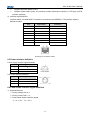
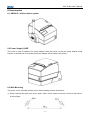
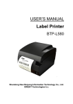
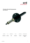
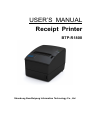
USER’S MANUAL Receipt Printer BTP-R180II Shandong New Beiyang Information Technology Co., Ltd BTP-R180II User’s Manual Declaration Information in this document is subject to change without notice. SHANDONG NEW BEIYANG INFORMATION TECHNOLOGY CO., LTD. (hereinafter referred to as “SNBC”) reserves the right to improve products as new technology, components, software, and firmware become available. If users need further data about this product or have any doubt about safety issues that might arise from using it, please feel free to contact SNBC or your local agents. No part of this document may be reproduced or transmitted in any form or by any means, electronic or mechanical, for any purpose without the express written permission of SNBC. Copyright Copyright© 2014 by SNBC Printed in China Version 1.1 Trademarks Our registered trademarks are Warnings and Cautions Warning: Items shall be strictly followed to avoid damages to body and equipment. Caution: Items with important information and prompts for operating the printer. Certifications The control system of SNBC has been approved of the following certifications: ISO9001 quality control system certification ISO14001 environmental control system certification OHSAS18001 occupational health and safety control system certification IECQ QC080000 hazardous substance process control system certification Technical Contact Information Address: No.169 Huoju Road High-tech Zone, Weihai, China Hot line: 400-618-1368 800-860-1368 Fax: +86-631-5656098 PC: 264209 Website: www.newbeiyang.com.cn -1- BTP-R180II User’s Manual General Safety Information Before installing and using the printer, please read the following items carefully. 1. Safety instructions Don’t touch the tear bar of printer. The print head is a thermal element and it is at high temperature during printing or just after operation, therefore please do not touch it and its peripherals for safety reasons. The thermal head is an ESD-sensitive device. To prevent damage, do not touch either its printing part or connecting parts. 2. Caution 1) Install the printer on a flat and stable place. 2) Reserve adequate space around the printer so that convenient operation and maintenance can be performed. 3) Keep the printer away from water source. 4) Do not use or store the printer in a place exposed to heat of fire, moisture, serious pollution and direct sunlight. 5) Do not place the printer on a place exposed to vibration or impact. 6) No dew condensation is allowed to the printer. In case of such condensation, do not turn on the power until it has completely evaporated. 7) Connect the DC adapter to an appropriate grounding outlet. Avoid sharing a single electrical with large power motors and other devices that may cause the fluctuation in voltage. 8) Disconnect the DC adapter when the printer is not used for a long time. 9) Don’t spill water or other materials on the printer. If this happens, turn off the power immediately. 10) Do not allow the printer to start printing when there is no recording paper installed, otherwise the print head and platen roller will be damaged. 11) To ensure quality print and normal lifetime, use recommended or good quality paper. 12) Shut down the printer when connecting or disconnecting interfaces connectors to avoid damage to the control board. 13) Set the print darkness to a lower grade as long as the print quality is acceptable. This will help to keep the print head durable. 14) The printer should only be disassembled or repaired by a technician, who is certified by the manufacturer. 15) Keep this manual safe and at hand for ready reference. 16) The following content about cutter only applies to printers with cutter. -2- BTP-R180II User’s Manual Contents Declaration .............................................................................................................................................. - 1 - 1 Introduction ......................................................................................................................................... - 5 - 1.1 OUTLINE .................................................................................................................................................................... - 5 - 1.2 FEATURES .................................................................................................................................................................. - 5 - 2 Specifications ...................................................................................................................................... - 6 - 2.1 MAIN SPECIFICATION ................................................................................................................................................. - 6 - 2.2 CUTTER SPECIFICATION ............................................................................................................................................. - 7 - 2.3 PAPER SPECIFICATION ................................................................................................................................................ - 7 - 2.3.1 Continuous paper ........................................................................................................................................... - 7 - 2.3.2 Mark paper ...................................................................................................................................................... - 8 - 2.4 PRINT AND TEAR OFF POSITION .................................................................................................................................. - 9 - 2.4.1 Print position ................................................................................................................................................... - 9 - 2.4.2 Tear off position .............................................................................................................................................. - 9 - 3 Outline and components .................................................................................................................. - 10 - 3.1 OUTLINE AND PARTS ................................................................................................................................................ - 10 - 3.2 ERROR LED AND BUZZERS .......................................................................................................................................- 11 - 3.2.1 Error LED ...................................................................................................................................................... - 11 - 3.2.2 Description of LED and Error Status ......................................................................................................... - 11 - 4 Installation ......................................................................................................................................... - 12 - 4.1 UNPACKING ............................................................................................................................................................. - 12 - 4.2 PRINTER INSTALLATION ........................................................................................................................................... - 12 - 4.3 CONNECTING THE POWER ADAPTER ........................................................................................................................ - 12 - 4.4 CONNECTING INTERFACE CABLE .............................................................................................................................. - 13 - 4.5 CONNECTING THE CASH DRAWER ............................................................................................................................ - 13 - 4.6 PAPER ROLL LOADING .............................................................................................................................................. - 13 - 4.6.1 Confirm the paper type ................................................................................................................................ - 13 - 4.6.2 Load/replace a paper roll ............................................................................................................................ - 13 - 4.7 PAPER NEAR END ADJUSTMENT ................................................................................................................................ - 14 - 4.7.1 Paper near end position adjustment ......................................................................................................... - 14 - -3- BTP-R180II User’s Manual 4.7.2 Remaining paper amount adjustment of Paper near end sensor ......................................................... - 15 - 4.8 POWER ON PRINTER AND PRINT SELF-TEST PAGE ...................................................................................................... - 15 - 4.8.1 Power on printer ........................................................................................................................................... - 15 - 4.8.2 Print self-test page ....................................................................................................................................... - 15 - 5 Printer maintenance .......................................................................................................................... - 16 - 5.1 PRINT HEAD AND ROLLER CLEANING........................................................................................................................ - 16 - 5.2 MARK SENSOR CLEANING ........................................................................................................................................ - 16 - 5.3 CLEAR PAPER JAM .................................................................................................................................................... - 16 - 6 Interface Signal.................................................................................................................................. - 18 - 6.1 PARALLEL INTERFACE .............................................................................................................................................. - 18 - 6.2 RS-232 SERIAL INTERFACE ...................................................................................................................................... - 19 - 6.3 USB INTERFACE....................................................................................................................................................... - 19 - 6.4 ETHERNET INTERFACE ............................................................................................................................................. - 19 - 6.5 POWER INTERFACE DEFINITION ................................................................................................................................ - 20 - 6.6 CASH DRAWER INTERFACE SIGNAL DEFINITION ........................................................................................................ - 20 - 7 Troubleshooting ................................................................................................................................ - 22 - 7.1 PRINTER DOESN’T WORK .......................................................................................................................................... - 22 - 7.2 ERROR LED AND BUZZER ........................................................................................................................................ - 22 - 7.3 PROBLEMS DURING PRINTING .................................................................................................................................. - 22 - 8 Accessories ....................................................................................................................................... - 23 - 8.1 HERALD – KITCHEN ALARM SYSTEM ..................................................................................................................... - 23 - 8.2 POWER SUPPLY CASE ............................................................................................................................................. - 23 - 8.3 WALL MOUNTING .................................................................................................................................................... - 23 - 9 Power Management ........................................................................................................................... - 25 - -4- BTP-R180II User’s Manual 1 Introduction 1.1 Outline BTP-R180II is a high performance thermal printer, which can be widely used for real-time printing application, such as POS system, restaurant system, ATM, etc. BTP-R180II can be connected with other devices via serial interface, USB, Ethernet and is available for WINDOWS 2000/XP/Server 2003/VISTA/WIN7/WIN8/Server2008/Server2012 and Linux. 1.2 Features ◇ Low noise, high printing speed ◇ Easy paper loading ◇ Easy use and maintenance ◇ Marked paper and continuous paper available ◇ Compatible with various wide paper ◇ Cutting paper automatically ◇ Cash drawer control connector ◇ ESC/POS compatible ◇ Built-in Internal Buzzer ◇ Save paper function ◇ Low consumption design -5- BTP-R180II User’s Manual 2 Specifications 2.1 Main specification Item Color Printing Specification Black or Ivory Print Method Direct Thermal Resolution 180 × 180 DPI(standard) Paper width 57.5/69.5/76/80/82.5mm Print width Max. 72mm Print speed Max. 230mm/s Flash capability 2M / 4M (selectable, according to different font library) Flash LOGO Max. 512K bytes Data buffer 64K bytes,4K bytes,45 bytes Serial (RS-232, Fix on board) Interface USB2.0(Full Speed, Fix on board) Ethernet(Fix on board) Printer Status Detection Top cover position, Paper end, Print head overheating, Print voltage, Paper near end,Marked detection,Cutter error 1D:UPC-A,UPC-E ,JAN8 (EAN8),JAN13 (EAN13), CODE 39,CODE Barcode 93,CODE 128, ITF,CODABAR 2D: PDF417,QR,MaxiCode GS1 Fonts Type DataBar Font A 12×24,Font B 9 ×17 ,kanji 24 × 24, 95 Alphanumeric, Characters 13 types International characters Traditional/Simplified Chinese, Japanese, Korean (optional) Command Emulation Supported Paper Power Supply Paper type Continuous paper, Marked paper Paper OD Max 83mm Paper thickness 0.06mm~0.08mm Input 100-240VAC, 50-60Hz Output 24V ± 5%V DC, 1.5A External Only Power Adaptor EMC and Safety Standards HumanMachine Interface Reliability ESC/POS™ CCC、CE、CB、FCC、UL Power switch Micro switch Button FEED button LED POWER LED, ERROR LED Buzzer Built-in buzzer Lifetime of print head 150 km(standard test condition) Lifetime of cutter 1,500,000 cuts(standard test condition) MCBF 60,000,000 lines MTBF 360,000 hours Operation condition 5°C to 45°C, 20% to 90%RH (40°C) -6- BTP-R180II User’s Manual Storage condition -40°C to 60°C, 20% to 93%RH (40°C) Dimension 195 L x 145 W x 141 H (mm) Weight Functions Approx 1.45Kg Cash drawer 2 drives Feed button config Support(config the printer without computer) Bi-colour printing Support Right-up-side Support Water mark Support Optional Accessories Spill proof Cover, Herald, Power Adapter Cover Win2000(32), WinServer2003(32&64), WinServer2008(32&64), Driver WinServer2012(32&64), WinXP(32&64), WinVISTA(32&64), OS Win7(32&64),Win8(32&64), Linux CUPS, OPOS, JavaPOS Printer Utility(include EEPROMset, LOGO download, customized Software codepage) 2.2 Cutter Specification Item Parameter Note Cutter type Slide cutter Cutting time 500ms The time that one cut takes Cutting interval 3s 20 times/min. (Max.) Paper type 0.06~0.08mm Thermal paper or paper with the same thickness Operation voltage 24VDC Max. dynamic current 1.5A 24VDC Cutter lifetime 1500,000 cuts (reference paper with thickness of 0.06 mm) Full or partial cuts Full cut: Cut off the paper completely Partial cut: 2 mm paper left in middle 2.3 Paper Specification 2.3.1 Continuous paper Paper type: Continuous thermal paper Paper supply method: Paper roll Paper width: 82.5±0.5mm,80±0.5mm, 76±0.5 mm,69.5±0.5mm Paper thickness: 57±0.5mm 0.06mm-0.08mm Thermal senstive layer: Outside Paper house specifications OD: фMax. 83mm Recommended reference paper: Paper type Manufacturer TF50KS-E2C,TF50KS-E Nippon Paper Industries Co., Ltd. F70NA FUJI PHOTO FILM Co., Ltd. F240AC/F220-VP, Mitsubishi Paper Mill Co., Ltd. FV230A1,PA220AG, -7- BTP-R180II User’s Manual HP220A PD150R, PD160R OJI Paper Co., Ltd. F5041, F5051, P5045, Mitsubishi HitTec Paper Flensburg P5055 GmbH KF50, KP440 Kanzan Spezialpapiere GmbH KT55F20, KT58F20, KT55HS Papier-fabrik August Koehler AG P300, P350, P530 Kanzaki Specialty Paper Caution: Please use the recommended reference paper type or its equivalents. Using the lower quality paper types might affect the print quality and shorten print-head life. If the paper is contaminated by chemical or oil, it may discolor or lose heat sensitivity at the polluted spot. Do not rub the paper surface strongly against hard objects, otherwise it may discolor. When the temperature goes up to 70 degrees centigrade, paper will discolor. Don’t use or store paper under high temperature, high humidity and strong light conditions. 2.3.2 Mark paper In mark paper mode, BTP-R180II determines the cut position and the initial printing position by referencing the position of the black mark. Black marked paper should meet the following requirement besides that of standard paper. 3mm≤L1(mark width)≤13mm. L2 (mark length) ≥10mm. 20mm≤L3 (distance between two marks) <300mm. Mark position: left side (only 80mm paper available) or middle of paper. Reflectivity: The reflectivity of the black mark must be less than 15% while the reflectivity of the paper itself exceeds 85%. There shall be no printed objects like text and images in the area between the black marks. Caution: The printer will measure the marks during the printing or feeding process. If the lengths of the mark (L1) is larger than the default value (default: 13mm), the printer will give a paper-end alarm. -8- BTP-R180II User’s Manual 2.4 Print and tear off position 2.4.1 Print position L1: Paper holder width: 83.5±0.5mm L2: Max Print width: 72mm L3: Distance between left end of print-head and left side of paper house (Fixed) 1.75±1mm L4: Distance between right end of print-head and right side of paper house(Fixed) 1.75±1mm L5: Left margin (default:0mm) L6: Print area width. Can set by command (See Programming Manual) L7: Right margin (default: 0mm) 2.4.2 Tear off position L1 (Distance between Top printing line and Tear off position): about 28mm L2 (Distance between Top printing line and Auto cutting position): about 11.6mm -9- BTP-R180II User’s Manual 3 Outline and components 3.1 Outline and Parts 1—Power LED 2—Error LED 3—Feed button 4—Tear bar 5—Top cover latch 6—Cutter cover 7—Middle cover 8—Power switch 9— Bottom cover 10—Top cover 11—Top-cover-open sensor 12—Paper sensor 13—Paper guide 14—Printer platen 15—Power connector 16—Cash drawer connector 17—Ethernet interface 18—Serial interface 19—USB interface Functions of parts: a- Power Indicator (1) Indicating power status (ON/OFF). b- Error indicator (2) Indicating some error status. Under normal conditions, ERROR LED is always off. Under some error conditions (e.g. paper end), ERROR LED will flash. c- Feed button (3) Feed paper function Printer will feed paper when the FEED BUTTON is pressed down under normal condition. Printer will feed long length paper if keeps pressing down the button. Print self-test page Press down FEED button while turn on the power, the printer will print out self-test page, including print length, print width, print speed and so on. Enter button config function Press down FEED button while turn on the power, the printer will print out self-test page. - 10 - BTP-R180II User’s Manual Printer will stay in pause state after cutting paper (ERROR LED flashes).Then keep pressing FEED button, the printer will enter button config mode. d- Power switch (8) “O” power is to turn off printer. “—” power is to turn on printer. e- Top cover uplifting alarm sensor (11) Monitor top cover status: open/close. f- Paper end sensor (12) To detect if paper is existing or not when using continuous paper; To detect the paper mark when using black mark paper. g- Paper guide (13) There are 4 long slots in paper house bottom. Paper house width can be adjusted to below different value by inserting paper guide into different slots:82.5 ±0.5mm ,, 80±0.5 mm,76±0.5 mm,69.5±0.5 mm, 57±0.5 mm. the paper house width is 82.5 ±0.5mm if take out the paper guide Caution: The paper guide is an indispensable part of the printer and should be kept with the printer. 3.2 Error LED and Buzzers 3.2.1 Error LED LED Power Indicator (Green) (POWER) Error Indicator (Red) (ERROR) Status Description On Printer is powered on Off Printer is powered off Off Printer is in normal status Flash Printer is in error status or Paper near end 3.2.2 Description of LED and Error Status Error information ERROR LED Buzzer Print head is overheating Six times Six times Input voltage is abnormal Five times Five times Cutter Error Four times Four times Cover Is Open Three times Three times Paper End Twice Twice Paper near end One times - One times - Calibration error or can not find the marks Caution: The temperature of the print-head is detected by means of a thermistor sensor. If the temperature of the print head becomes higher than 65℃, the protection circuit of the printer will force the printer to stop printing. - 11 - BTP-R180II User’s Manual 4 Installation 4.1 Unpacking Check whether all items, which are listed on the packing list, are present and in a good condition. If any item is damaged or missing, please contact your dealer. 4.2 Printer installation The BTP-R180II can be installed in two positions: horizontally on a table or vertically on a wall. 1. 2. Horizontally on a table Vertically on a wall 4.3 Connecting the Power Adapter 1) Confirm the power switch is turned off. 2) Insert the power cord into the power socket on the back of the printer. Caution: Use only the manufacturers supplied power adapter or other equal model. When connecting or disconnecting the cable connector of the power adapter, always hold the connector but not the cable. Do not pull on the power adapter cord, otherwise the cord may be damaged or broken, causing a risk of fire or electric shock. Do not place the Power adapter cord near a heating device; otherwise, the cover of the cord may melt, - 12 - BTP-R180II User’s Manual causing a risk of fire or electric shock. When the printer is not in use for a long period of time, disconnect the Power adapter from the wall outlet for safety. 4.4 Connecting interface cable 1) Confirm the power switch is turned off. 2) Connect the suitable interface cable with the correct connector to the connector of the interface board of the printer plug screws (Serial interface) or clip springs (Parallel interface). 3) Connect the other end of the interface cable to the host. 4.5 Connecting the Cash Drawer 1. Confirm the printer power is turned off. 2. Insert the cash drawer cable into the cash drawer connector on the back of the printer. Caution: Cash drawer interface can be connected only with a cash drawer device (Do not connect a telephone line and so on). 4.6 Paper roll loading 4.6.1 Confirm the paper type After connecting of the printer to the mains voltage, with the host and, if applicable, to the cash drawer, the paper can be loaded and printed. 4.6.2 Load/replace a paper roll 1) Turn off the printer. 2) Open the printer top cover, as in the following figure. 3) Drop in a paper roll in the paper house. 4) Pull the paper roll into the paper holder, and close the printer top cover. 5) Tear off the surplus portion of the paper by using the tear bar. Caution: User can adjust the paper guide position according to the paper roll width as following steps: hold the hole on back of paper guide and rotate it upwards , then take out the guide; insert it downwards into the right slot as the paper width; Be sure that the paper rolling direction to be correct as shown in - 13 - BTP-R180II User’s Manual above picture. Without paper guide: 82.5±0.5mm. Paper guide in the slot 1: 80±0.5mm Paper guide in the slot 2: 76±0.5mm Paper guide in the slot 3: 69.5±0.5mm Paper guide in the slot 3&4: 57 ±0.5mm Confirm that the paper is rolled tightly on the paper roll, otherwise, paper jam or other fault may occur. The paper roll should be placed straight in the paper compartment and not at an angle. The paper roll should be able to move freely. 4.7 Paper near end adjustment 4.7.1 Paper near end position adjustment BTP-R180II supports printing both in horizontal and vertical positions. Users can detect the remaining paper in the horizontal and vertical position by adjusting the paper near end sensor. The default printer setting is for horizontal printing and the paper near end sensor is at the bottom of the paper compartment. To change the paper near end sensor position from horizontal to vertical: First, press the plastic release - 14 - BTP-R180II User’s Manual button in position 1 along the direction of the arrow. Then rotate thumbwheel in the direction shown. The paper near end sensor will start to rotate. When the release button rotates to position 2, the change from horizontal to vertical is complete. 4.7.2 Remaining paper amount adjustment of Paper near end sensor Remaining paper amount can be adjusted by adjusting the position of paper near end sensor Paper near end sensor has six levels, the red mark (actual color on printer is white) shows the current level and it can be adjusted to a different position by moving the click-wheel. 4.8 Power on printer and print self-test page 4.8.1 Power on printer Confirm that the printer is connected to power. 4.8.2 Print self-test page 1) Confirm that the printer is connected to power and paper roll is loaded. 2) Confirm that the printer is switched off. 3) Press down the FEED button while turning on the printer power. The configuration page. At the end of the configuration page the followings text will appear: “Press and Release FEED to continue SELF-TEST printing” and “Press and Hold FEED to configure the printer” The printer is holding and waiting for the input while the PAPER LED is flashing. 4) Press down the FEED button momentarily, the printer will print a character test page which is a part of the self-test. - 15 - BTP-R180II User’s Manual 5 Printer maintenance Caution: Before starting routine maintenance, confirm that the printer power is turned off. Do not use solvents like gasoline or acetone. When cleaning sensors, the printer should not be switched on until the pure alcohol has totally evaporated. It is recommended that the maintenance cycle should not be longer than one month. 5.1 Print head and roller cleaning Steps for TPH and roller cleaning are as follows: 1) Turn off the printer power and open the top cover. 2) If printing is just finished, please wait until the print head is completely cooled. 3) Use cotton moistened with alcohol (wringed out) to wipe away the dust on the surface of print head and roller. 4) Wait until the alcohol is completely evaporated, then close the top cover. 5.2 Mark sensor cleaning If the printer does not identify the mark effectively, you should clean the mark sensor. Steps for mark sensor cleaning are as follows: 1) Turn off the printer. 2) Pull the latch to open the back cover of the printer. 3) Keep the back cover open, clean the dust and dirt off the mark sensor using a soft cotton cloth with a little alcohol. 4) Wait until the alcohol completely evaporated then close the back cover and finish mark sensor cleaning. 5.3 Clear paper jam Steps for clearing a paper jam are as follows: 1) Turn off the printer power, and open top cover. 2) Clear paper jam and close the top cover. 3) If top cover cannot be opened with paper jammed into the cutter, push up both right and left sides of top cover together with two hands according to the arrow direction in below figure, pull out the front cover and expose the white thumb wheel on the cutter sliding blade. 4) Revolve the white thumb wheel on the front end of the cutter by hand; observe the action of the cutter from the paper path the top cover can not be opened until the cutter sliding blade deviates from the stationary blade completely, then clear paper jam. - 16 - BTP-R180II User’s Manual Caution: The cutter sliding blade acts slowly during revolving the thumb wheel. Go on revolving and observe carefully; If the thumb wheel cannot be turned, do not force the wheel, instead turn it the opposite direction. - 17 - BTP-R180II User’s Manual 6 Interface Signal 6.1 Parallel interface Parallel interface can work in IEEE 1284 compatible mode or half-byte mode. The interface is 36PIN CENTRONICS. The Interface is defined as below: PIN Source Function 1 H nStrobe 2 H Data 0 (Least Significant Bit) 3 H Data 1 4 H Data 2 5 H Data 3 6 H Data 4 7 H Data 5 8 H Data 6 9 H Data 7 (Most Significant Bit) 10 P nAck 11 P Busy 12 P Perror 13 P Select 14 H nAutoFd 15 Not defined 16 Logic Gnd 17 Chassis Gnd 18 P Peripheral Logic High 19 Signal Ground (nStrobe) 20 Signal Ground (Data 1) 21 Signal Ground (Data 2) 22 Signal Ground (Data 3) 23 Signal Ground (Data 4) 24 Signal Ground (Data 5) 25 Signal Ground (Data 6) 26 Signal Ground (Data 7) 27 Signal Ground (Data 8) 28 Signal Ground (PError, Select, and nAck) 29 Signal Ground 30 (Busy and nFault) Signal Ground (nAutoFd, nSelctIn, and nInit) 31 H nInit 32 P nFault 33 Not defined 34 Not defined 35 Not defined 36 H nSelectIn - 18 - BTP-R180II User’s Manual 6.2 RS-232 serial interface The serial interface of the printer is compatible with RS-232, its connector is 9PIN female D type. PIN No. Signal definition PIN1 Not connected PIN2 RXD PIN 3 TXD PIN 4 DTR PIN 5 Signal Ground PIN6 DSR PIN 7 DTR PIN 8 DSR PIN 9 Not connected User can query interface settings status via printing self-test page. The default setting is as follows: Baud rate: 9600bps, Data bit: 8, Parity bit: none, stop bit: 1 Handshake: DTR/DSR 6.3 USB interface Parameters Data transmission: Support USB2.0 Full-speed protocol Connector (Printer side): USB B type socket. Support and pass USB HUB 1) Interface signal definition and functions PIN Signal Name Description 1 VBUS +5V 2 DATA- data transmit line minus 3 DATA+ data transmit line plus 4 GND Ground 2) Interface Connector 6.4 Ethernet interface 1) Interface features Support of 10/100M BASE-T communication Compatible with Ethernet II standard frame type Indicator shows network connecting status and data transmission status Supports 9100 port print Supports status back Supports parameter configuration - 19 - BTP-R180II User’s Manual Supports firmware update on-line Supports printer status query and interface module maintenance based on HTTP(only JK-E02 interface supports) 2) Interface signal definition Interface adopts 10/100M BASE-T standard in accordance with IEEE802.3. The interface signal is defined as below: PIN Signal Name Instruction 1 TX+ Data transmission + 2 TX- Data transmission - 3 RX+ Data receiving + 4 NC Reserve 5 NC Reserve 6 RX- Data receiving - 7 NC Reserve 8 NC Reserve Socket figure of Interface module 6.5 Power interface definition Power supply interface signal definition PIN Signal Name 1 E 2 L 3 N Power socket 24V power interface definition PIN Signal Name 1 E 2 L 3 N 6.6 Cash drawer interface signal definition 1) Electrical features Driving voltage: DC 24 V Driving current: Max. 1 A Cash drawer status inspection signal: “L” = 0~0.5 V “H” = 3.3 V - 20 - BTP-R180II User’s Manual 2) Cash drawer interface outlet uses RJ-11 6P connector. 3) Interface signal definition PIN Signal Name Functions 1 FG Frame Ground 2 DRAWER 1 Cash drawer 1 driving signal 3 Cash drawer status test DRSW signal 4 VDR Cash drawer driving power 5 DRAWER 2 Cash drawer 2 driving signal 6 GND Circuit share ground Caution: Do not connect or disconnect signal cable when printer power is on. Signal cable should be far away from strong current. Signal cable should be far away from strong current sources. - 21 - BTP-R180II User’s Manual 7 Troubleshooting In case of printer fault, consult this section for solutions and advice. If you do not find a solution in this section, please contact your local dealer for assistance. 7.1 Printer doesn’t work Problems LED is off and the printer doesn’t work Possible causes Solution Printer has no power supply Connect the printer power Printer power is off Turn on the printer power Circuit is damaged Contact your local dealer. or manufacturer 7.2 Error LED and Buzzer Problems Error LED flashes and buzzer beeps Possible Causes Paper end Replace roll paper Cutter error Refer to 7.4 Cutter error troubleshooting Top cover up Close top cover Print head overheated Buzzer beeps and error LED on Solution These indicate a serious problem Turn off printer power and wait until the print head turn to normal temperature. Contact your local distributor or a technician of manufacturer for assistance. 7.3 Problems during printing Problems Paper cannot be fed normally Printer starts printing but stops suddenly Paper is not cut Possible Causes Open top cover to check paper path and Paper jam cutter and remove paper jam Open top cover to check the cutter and Paper jam remove paper jam Open top cover to check the cutter and Paper jam remove paper jam Paper roll is not installed correctly Printout is not clear or dirty Vertical column of print is missing Solution Make sure that the paper roll has been installed correctly Paper is out of specification Use recommended thermal paper Dirty print head or platen roller Clean the print head or the platen roller Print darkness is too low Increase the print darkness as needed Dirty print head or platen roller Clean the print head or the platen roller Print head error Contact your local dealer. - 22 - BTP-R180II User’s Manual 8 Accessories 8.1 HERALD – kitchen alarm system 8.2 Power Supply CASE This cover is used to install the AC power adapter under the printer; so that the power adapter would become an internal part of the printer (the power adapter will be inside of the printer). 8.3 Wall Mounting The printer can be mounted vertically on the wall according to below instructions: 1) Drill two holes (holes (OD: 6mm: 6mm, depth: 50mm: 50mm, space of two hole: 75mm) on the wall as in below figure: - 23 - BTP-R180II User’s Manual 2) Insert the plastic plugs in the holes and make sure that the plugs are fully inside the holes and do not stick out. 3) Screw the two screws in the plastic plugs and keep10mm space between the screw head and the wall surface. 4) Regulate the paper near end sensor (Please refer to 4.7), and mount the printer as figure. - 24 - BTP-R180II User’s Manual 9 Power Management The power management of BTP-R180II has four operation modes: Ready, Active, Sleep, Off. 1. Printer will enter into Ready mode after powering on printer or completing printing job. 2. Printer will enter into Sleep mode if there is not any printing job for 5 minutes in Ready mode. 3. Printer will awake automatically and enter into Active mode when printing job comes, and will enter into Ready mode again after completing printing job. Relating Parameter of power management is as below: Maximum Default Delay Times < 5min Because the Maximum Default Delay Times is less than 5 minutes, BTP-R180II does not open the port of changing this time to end user. - 25 -