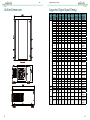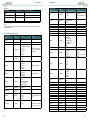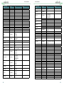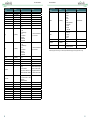
1
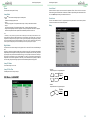
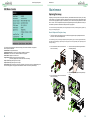
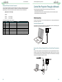
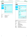
DU9000 ® Index Safety Notice 4 General 8 I/O Panel 8 Keypad and LED Keypad Indicator LED 9 9 9 Copyright Disclaimer About the Manual Disposal of Old Electrical and Electronic Equipment Important Recycling Instructions Important Safety Guidelines Installation and Use Notice Introduction Product Features Packing Checklist Projector Overview 4 4 4 4 4 5 5 6 6 7 7 Remote Control 10 Installation of the Remote Control Battery 11 Remote Control Operating Range 11 Precautions For Installation 12 Projector Installation and Setup 12 Cautions on Ventilation 13 Lens Shift Vertical and Horizontal Lens Shift 14 14 Connecting the Projector to Source Devices Connecting to a Computer Connecting to Video Equipment Connecting to Control Equipment HDBaseT/LAN (Network Control) RS-232 (RS-232c Control) Wired Remote Control 3D Sync Connecting to the Screen Trigger Connecting to the External HDBaseT Transmitter 15 15 15 15 15 15 15 15 16 16 1 ® Before Using the Projector 17 Remove Dust Cover Before Turning on Power 17 Connecting to AC Power 17 AC Outlet 18 Turn On 19 Changing the OSD Language 19 Adjusting the Projection Mode Front Table Rear Table Front Ceiling Rear Ceiling Rear Tabletop 20 20 20 20 20 20 Lens Adjustment Vertical Lens Shift Horizontal Lens Shift Zoom In/Out Focus 20 20 20 20 20 Start Using the Projector-Operation Select the Input Source Select the Aspect Ratio Use OSD (OnScreen Display) 2 ® 21 21 21 21 OSD Menu Tree 21 OSD Menu - Main Selection 25 OSD Menu - MAIN Aspect Ratio Preset Input Selection 3D Control 25 26 27 27 27 OSD Menu - IMAGE Picture Model Brightness Contrast Saturation Sharpness Hue Noise Reduction 29 29 29 29 29 29 29 29 OSD Menu - ADVANCED IMAGE Color Space Gamma Color Temperature Dynamic Black Adaptive Contrast HSG 30 30 30 30 30 30 31 OSD Menu - LAMP Lamp Mode Power Lamp Select High Altitude Lamp 1/2 Status Lamp 1/2 Run Time 31 31 32 32 32 32 32 OSD Menu - ALIGNMENT Lens Control Center Lens Warp Blanking Edge Blend Test Pattern 32 33 33 33 34 35 35 OSD Menu - Control Language OSD Setting Blank Screen Projection Mode Auto Power Off Auto Power On Startup Splash Trigger 1 & 2 Auto Source Infrared Remote Network 36 36 36 36 36 37 37 37 37 37 37 37 OSD Menu - Service 38 Maintenance 39 Replacing the Lamps How to Replace the Projector Lamp 39 39 Installing or Removing the Projection Lens Remove Lens Install Lens 40 40 40 Replacing the Filter 41 Outline Dimensions 42 Supported Signal Input Timing 43 3D Signal Input Mode & Timing 44 Serial Interface RS-232 Command Communication Parameter Setup Operation Commands List of Operation Commands Simulated IR Remote Controller Commands 45 45 45 46 52 Control the Projector Through a Network 53 Cable Connection Connect the Projector to a PC Connect with an External Integrated Video and Control Signal Transmission Box 53 53 53 Set Up the Projector for Networking 54 Control the Projector Through a Network Control the Projector Through a Web Browser Control Projector with the PJLink Protocol Control Projector with TCP/IP Communication Protocol 55 55 58 58 Specificatons and Support 59 Specifications 59 Vivitek Support 60 3 ® Safety Notice Safety Notice Safety Notice ® Important Safety Guidelines Copyright Thank you for purchasing this high quality product! Read the Manual carefully in order to obtain the best performance from your projector, please read the manual completely. The User's Manual (including all pictures, illustrations and software) is protected by the international copyright right law. All rights are reserved. Installation and Use Notice No duplication of the manual or any content included in the manual is allowed without the written consent of the manufacturer. 1. 2. 3. 4. ©2014 Vivitek. Vivitek is a trademark of Delta Electronics, Inc. Other trademarks are the properties of their respective owners. Disclaimer The information in the manual is subject to change without notice. The manufacturer does not provide any statement or warranty of the contents in the manual and clearly give up the implied warranties of merchantability and of fitness for a particular purpose. The manufacturer reserves the rights to modify the publication and change the contents of the materials at any time without notice to any person. About the Manual The manual describes how to install and use the DLP projector and is applicable to the end-user. Relevant information (such as illustrations and descriptions) is put on the same page as possible. The format, easy for printing, is convenient for reading and paper-saving which is beneficial to environmental protection. The manual format has been designed for ease of reading while respecting environmental and paper conservation. Disposal of Old Electrical and Electronic Equipment 5. 6. 7. 8. 9. 10. 11. 12. 13. 14. Please read and keep the manual available for future reference. Pay attention to all warnings. Follow all guidelines and recommendations. Do not put the equipment near water. Do not install the equipment near a heating duct thermal source, such as heater, radiator, furnace or other equipment that will generate heat. Use dry fabric to clean only. Do not obstruct any vents. Carry out installation according to the guidelines of the Manufacturer. Do not destroy the safety protection function of polarized or grounding plugs. A polarized plug has one wide and one narrow blade. A grounded plug has two blades and a third grounding prong. The wide blade or grounding blade is provided for the safety concerns. If the plug provided does not match the outlet, contact an electrician to replace the outlet. Prevent the power cord from being compressed or pinched, especially the power cord on the plug, outlet and the connection between the power cord and the equipment. Only use the connectors/accessories designated by the Manufacturer. Be careful when moving the trolley/equipment and avoid injury due to turning-over when using the trolley. Unplug the power cord of the equipment if there is a thunderstorm or the equipment will not be used for a long time. Ensure only Authorized Service personnel perform any necessary repairs or maintenance. Failure to do so, will void warranties. The packaging materials should be kept properly for future use and transportation. Do not look straight at the lens when the projector is running. The product can be used safely below a elevation of 3000 meters. There may be safety risk if the product is used above a elevation of 3000 meters. The symbol on your product or the package represents that the product should not be treated as the usual household waste when discarded but should be carried to the recycling location of the waste electric and electronic equipment.The consequence on the environment and human health due to the incorrect disposal of the product can be prevented when the product is properly discarded. Material recycling is helpful to the protection of natural resources.The symbol is only valid in European Union.If you want to discard electrical and electronic equipment, contact local authorities or dealer for the correct method of disposal. Important Recycling Instructions The lamp of the product contains mercury. The product may contain other electronic wastes and may pose risk if not discarded properly. Abide by the local, state/provincial or federal laws of recycling or discarding. For more information, please visit the website and contact Electronic Industries Alliance (EIA) at WWW.EIAE.ORG Please visit WWW.LAMPRECYCLE.ORG for the specific disposal information of lamps. 4 5 ® Safety Notice Safety Notice ® Introduction Packing Checklist The User's Manual describes the installation, setup and operation of the DU9000 projector and provides assistance to the installers and end users to fully ensure the performance of the projector. Vivitek has made every effort to ensure that the information in this Manual is correct at the time of printing. The contents may be updated due to product enhancements, customer feedback or improvements. You can find the latest version of the Manual and the manual of other Vivitek products at www.vivitekcorp.com. The following items are included in the DU9000 packaging. If any item is missing or damaged, please contact your dealer or Vivitek customer service center. Product Features The Vivitek DU9000 features advanced technology and industry leading optical design to provide a crisp, high resolution bright, crisp and vivid image. Main Characteristics and Advantages of the Product Series: • The DLP system with the high performance digital micro mirror device (DMD) in conjunction with advanced thermal management technology provides the excellent projecting performance and reliability. • The advanced dual-lamp optical engine as well as single-lamp, dual-lamp, normal, energy-saving and Custom Lamp Power mode offer flexible installation together with energy and cost savings. The lamp power can be adjusted in the normal and energy-saving modes to make it easier for the installation personnel to fine-tune the edge blending brightness of multiple projectors. • With the lamp switching feature, the projector can automatically select the lamps less used when turned on. • The projector has the replaceable color wheel and smart color wheel switch design. It can automatically detect and switch the parameter of corresponding color wheels and can be used in conjunction with the color wheel of high brightness or beautiful hues. It is applicable to the single projector. • The interchangeable lens design allows users change the suitable lens by pressing the Lens Release key easily and quickly. • With the complete series of motorized projection lenses, the horizontal shift, focusing and zooming of lenses can be electrically controlled. The throw ratio ranges from 0.84:1 to 4.0:1 is suitable to be used in most applications. • The mechanical shutter is built in the optical engine and allows the user to Blank/Freeze projection by pressing a single key. • The high performance video processor can be used in progressive and interlaced scanning of the video inputs and video diagnosing. • The complete input terminal support many input signals, such as HDMI, 3G/HD/SD SDI, HDBaseT, Component and VGA, etc. • With the built-in HDBaseT signal reception, HDBaseT transmitter can send high quality video and control signals through the single RJ45 cable. • Many 3D display formats is supported, such as Top/Bottom, Side by Side and Frame Packing. • The synchronization of DLP Link and 3D IR is supported with 3D Sync connector. • With the high efficient power switch, the power consumption is less than 5W on stand-by mode. 6 1. 2. 3. 4. 5. 6. 7. Power Cord (USA, Europe,China) Remote Battery (AAA) User's Manual CD Warranty Card (For China Only) HDMI Cable RHS Card (For China Only) *1 *3 *1 *2 *1 *1 *1 Projector Overview Vent Heat is discharged from the projector via the vent. Make sure the vent is not blocked. Intake/Filter Cover The internal fan pulls cool air into the projector via the intake. Adjustable Supporting Stand When the projector is installed on a desk, these stands can be used to adjust the levelness of the projection angle. Power Socket The power from the outlet on the wall is directed to the projector. Power Switch The switch is used to turn on or off AC power of the projector. LED Indicator and Keypad Use the buttons to select and adjust the settings of the projector or shows the status of the projector. Lens Release Button Push the Lens Release button to change the selected projector lens. IR Window The signal from the remote control can be received via the window. 7 Appearance ® General Appearance ® Keypad and LED I/O Panel INPUT MENU USB STBY ENTER IR RECEIVER HDBaseT/LAN Connect to the RJ45 Cat5 Ethernet cable. STAND BY ON ERROR LED STATUS 3D Sync Out Connect to the 3D IR synchronization signal transmitter. HDMI Connect to HDMI source. Keypad 3G/HD/SD SDI Connect to SDI source. STBY Use STBY button to turn on/off the projector. VGA Provide the standard 15-pin VGA connection and can connect to RGB, HD Component or personal computer. INPUT Push INPUT button to select the video source. HDMI, SDI, VGA, Component / BNC or HDBaseT. Component / Y/Pb/Rr Connect BNC-type input terminal to the RGB or YPbPr/YCbCr output signal of video equipment. RS-232 The 9-pin D-sub interface is used to connect to the PC control system and projector maintenance. MENU Push MENU button to display or hide the OSD menu. ENTER Use ENTER button to select settings or confirm the changed settings. Also push this button to enter and return to the OSD menu. TRIGGER (Trigger) The 3.5mm mini earphone jack provides 12V (+/-1.5) / 200mA Auto output for screen control. USB It is a port exclusively used for maintenance and only can be used by the authorized maintenance personnel. WIRE (Wired Remote Control) Connect to the input from the compatible IR transponder system and wired remote control. Wire remote control 3.5mm mini jack Tip -> Power Ring -> Signal Sleeve->Ground Tip Sleeve Ring Note: Please make sure the port for insertion is correct before the terminal of the wired remote control is inserted. The remote control may be damaged if it’s inserted to the wrong port. 8 Indicator LED Status Yellow (Standby) Blue (Power) Red (Error) Standby Cooling / Warm up Power on / Normal Lamp Fail Lamp Door Open Fan Fail Over Temperature System Error Repeat Repeat Repeat Repeat 9 Appearance ® Remote Control ON Use this button to turn on the projector. OFF Use this button to turn off the projector. FOCUS Adjust the focus of the projected images. ZOOM Zoom in/out the projected images. TEST PATTERN Use this button to display the test image. Press to switch to the next test image and press the RETURN button to return to the projected image. LENS SHIFT Use this button to shift the lens to the right, left, top or down. ENTER Use this button to select settings or confirm the changed settings. MENU Press the button to display or hide the previous level or OSD menu. Return Press this button to return to the menu on the exit the OSD menu. INPUT Press this button to select the input source. PICTURE Start to adjust the image. Appearance ® Installation of the Remote Control Battery NETWORK Press this button to enter the LAN menu. AUTO SYNC Press this button to carry out automatic signal synchronization. ASPECT Press this button repeatedly to select the proportion for the next screen. BLANK Press this button to temporarily interrupt the projection. OVERSCAN Press this button to select the overscan mode. 1. Slide the battery cover in the direction of the arrow. 2. Place two AA batteries with the correct polarity. 3. Slide the cover back. Battery installation instructions • Make sure that batteries are installed with the correct polarity. • Do not use old and new batteries or mix different types of batteries together. • Remove the batteries if the remote control will not be used for a long time to prevent. The damage caused by battery leakage. Remote Control Operating Range FREEZE Freeze/unfreeze the projected image. LAMP MODE Press this button to select dual lamp, Lamp 1 Lamp 2 or Single. 3D MODE Display the 3D settings menu. 10m ±30° INFO. Display the Projector message. LIGHT Not available for this model. Remote Control Instructions Reflection may be affected by the environment under some circumstances. Aim the remote control at the project to try again if it happens. Replace batteries with new ones if the effective distance of the remote control is decreased or the remote control does not work. When the terminal of the remote control cable is inserted to the wired control terminal of the projector, the projector will automatically switch to the wired control mode and cannot be controlled through the IR signal of the remote control. Disconnect the wired control terminal on the projector if you want to control through the IR signal of the remote control. ±30° 10m Note: Avoid exposing the remote control to a high temperature or humidity environment; otherwise, it could cause the remote control to malfunction. Pay attention to the installation environment because the signal may not work due to interference if the IR remote sensor is exposed to the bright sunlight or fluorescence. 10 11 ® Precautions For installation Precautions For Installation The high quality display effect can be guaranteed only when the projector is correctly installed. Generally, the light source facing the screen should be reduced or eliminated as much as possible. The contrast of images will be obviously reduced if the light such as the beam from glass window or searchlight directly shines on the screen. Images may appear faded and less vibrant. Precautions For installation ® Cautions on Ventilation This product is a high-brightness projector. The intakes with filters are located on the front and right sides to provide sufficient air cooling function. The projector has two vents on the back for cool air discharging. Make sure the intake and vent are unobstructed when the projector is being installed. At least 50cm around the intake and 70cm around the vent should be clear. Projector Installation and Setup There are 6 fixture screw holes at the bottom of projector for ceiling mounting. The available installation options are as below. Front: Install the projector on the table and project the image forward. Rear: Install the projector on the table and project the image from rear. Ceiling + Front: Mounting the projector on the ceiling and project the image forward. Ceiling + Rear: Mounting the projector on the ceiling and project the image from rear. 6 fixture screw for ceiling mount The screw is M6*17mm Note: The maximum length of screws is 18mm. ce n ta s i D cm 0 >5 st u m Dis ta >70 nce m cm ust ce n ta s i D cm 0 >5 st u m Ceiling mode Keep Distance of projector above 30cm Note: • If the installation distance is not enough, the projector may enter the system protection mode due to the rising ambient temperature after running for a while. Then, projection may be interrupted. • The service life of components or lamps may be reduced due to the high temperature around the projector. • If the projector has to be installed in a box or a closed environment, the external intake and vent system should be designed additionally to ensure that there is enough air for cooling or the projector will not be surrounded by heat. 12 13 Precautions For installation ® Precautions For installation ® Lens Shift Connecting the Projector to Source Devices The DU9000 projector has lens shift feature so the image can be vertically shifted without moving the projector. The lens shift bit is shown in the percentage of the screen height. The projector installed on the desk can move up and down. Follow the instructions below to connect the DU9000 projector to the video source, external control equipment (if any) and AC power supply. When connecting to the equipment, use the correct signal cable to connect to every signal source and ensure that the cable is securely connected. Fasten the nut on the joint and connect the signal source equipment to the projector according to the figure below. Vertical and Horizontal Lens Shift Connecting to a Computer The projector installed on the desk can move up and down. You can connect PC signal to the projector through the HDBaseT, HDMI, and RGB (BNC) cable. If the signal to be input is VGA signal, connect the VGA cable to the external display of the projected screen. A Lens Type Ultra Wide Angle Throw Ratio 0.84 ~ 1.03 Lens model name D98-0810 Focus (Optical) 1.5 ~ 4.0 Brightness(Tyical/Target) 100% Motorized Zoom/Focus Zoom: 1.22x Vertical Lens Shift@H Shift ±37.5% is 0% Horizontal Lens Shift@V ±12.5% Shift is 0% B Short Throw Lens 1.56 ~ 1.86 D98-1518 2~7 95% Zoom: 1.19x C Standard Lens 1.85 ~ 2.40 D98-1824 2.5 ~ 9 100% Zoom: 1.3x D Long Throw 2.40 ~ 4.0 D98-2440 4 ~ 12 100% Zoom: 1.67x ±50% ±50% ±50% ±15% ±15% ±15% USB Connecting to Video Equipment Connect the video equipment to the input port of the projector via the HDBaseT, HDMI, and Component Video Connector cable. Connecting to Control Equipment Vertical: The projector has the following control ports for connecting to the control equipment: V +50% V 0% V -37.5% V 0% HDBaseT/LAN (Network Control) The projector supports network control. LAN and HDBaseT share the same port. If only network control is used, you can connect the LAN on the projector to PC or through the local network. Refer to the remote control guidelines for detailed information. H 0% Horizontal: H +15% RS-232 (RS-232c Control) H 0% The projector supports RS-232c serial control. The projector can be remote-controlled by connecting the projector to PC or control system through the standard 9-pin serial cable (Straight through Serial Cable). Refer to the remote control guidelines for detailed information. H -15% V 0% V 0% H 0% Wired Remote Control If the projector cannot receive the IR signal from the remote control due to the overly long distance or obstacles, you can connect the cable to the IR remote control or the external IR transmitter (optional) via the WIRE input port to expand the working range of the remote control. H 0% 3D Sync 3D sync signal output for IR transmitter. Note: • When the terminal of the remote control cable is inserted to the wired control terminal of the projector, the projector will automatically switch to the wired control mode and cannot be controlled through the IR signal of the remote control. Disconnect the wired control terminal on the projector if you want to control through the IR signal of the remote control. • If the wired remote control cable or the external IR transmitter is inserted to the incorrect port, such as Trigger, the remote control or the IR transmitter may be damaged. Please do not plug IR remote into 12V trigger. Make sure whether the port is correct before insertion. 14 15 ® Precautions For installation Connecting to the Screen Trigger If your projection system includes the Electric projection screen and other 12V trigger device, you can connect these devices to the 12V trigger to output and configure the output 12V signal settings, such as automation and the aspect ration of 16:10 through OSD control to Trigger. The projector will output 12V signals according to the current settings of the aspect ratio and trigger when turned on. You can use the signal to control the screen or device. Before Using the Projector ® Before Using the Projector Remove Dust Cover Before Turning on Power Remove this plastic cover before turning on power and installing Lens. Connecting to the External HDBaseT Transmitter The projector has a built-in HDBaseT signal receiver. With the HDBaseT Transmitter (optional), the video, RS-232 and LAN signals can be sent to the projector via a single RJ-45 cable. If the HDBaseT Transmitter you purchased supports the input and output of the IR remote control, the control signals from the IR remote control can't be sent to the DU9000 projector via the RJ-45 cable. Note: The projector supports the video signal only, RS-232 and IR remote control are not supported. The reception of the network control signals is also supported. This projector do not support Power over Ethernet (PoE). If the Video content is sent via the HDBaseT transmitter, the longest transmission distance is 100 meters. The projection may be interrupted, interfered, or the control signal cannot be sent if the transmission distance is exceeded. Use the RJ-45 Cat5e cable and avoid entwining. Entwining may cause damage like interference of signal transmission, reduced transmission distance and degraded image quality. Connecting to AC Power There are three AC power cords included in the box. Before plug the power cord, please choose the compliant power cord for the AC Voltage in you region. The fuse is different from 110V and 220V, please switch before you plug power cord. Plug the power cord to AC socket (AC100V- 240V, please make sure the fuse is in correct Voltage) on the side of the projector and plug another end of the AC power cord to the AC outlet. 16 17 Befor Using the Projector ® AC Outlet Before Using the Projector ® Turn On Press ON on the remote control or STBY on the projector. The power and lamp LED indicator flashes blue to show warm-up. USA Europe China • Caution: Ensure that the power net meets the power requirements of the projector. When the power and lamp LED indicator lights are blue and the projector light is turned on, this mean that the projector is ready for use. Refer to Page 9 [Indicator LED] if the LED indicator flashes red. Please contact the Vivitek licensed dealer if the problem cannot be solved. • Warning: Do not attempt operation if the AC supply and cord are not within the specified voltage and power range. • Caution: Once the projector is switched to standby, the lamp cooling fans will continue to run for approximately five minutes to ensure that the projector and lamp have sufficiently cooled, at which point the fans will automatically decrease to standby. To avoid thermal stress that can lead to premature lamp failure, never unplug the power cord while the lamp cooling fans are running. Never unplug the power cord to power down the projector, first switch off the power switch and then unplug the power cord. Changing the OSD Language The projector can display English and Simplified Chinese menus. Press MENU to show OSD and press ▲▼ to select control items. Press ▲▼ to select language you want to use. Press Enter to confirm the selection. Make sure the power system (including the projector and power supply system) is properly grounded before connecting to the AC power. The projector may be damaged without the grounding circuit. This is a high-brightness and high-watt projector. Do not modify the AC power cord or replace the power cord arbitrarily to avoid causing damages to the projector or safety problems. 18 19 ® Befor Using the Projector Adjusting the Projection Mode The projection mode has influence on the direction of the projected image and cooling. The projection mode option can be used to change the direction of the projected screen and the cooling fan speed to ensure that the projector is properly cooled. The improper projection mode settings may trigger over heating or reduce the service life of lamps and elements. Please make sure the correct projection mode is set when installing the projector. Press the MENU button on the remote control or the control panel to bring up OSD and set the projection mode, Select CONTROL → Projection Mode Front Table Start Using the Projector ® Start Using the Projector-Operation Select the Input Source Press the INPUT Source button on the remote control to select the input source. Select the Aspect Ratio Press ASPECT to adjust the aspect ratio of the image. Installed on the desk and the projection screen will be shown in the normal direction. Rear Table Installed on the desk. The image will be projected from behind the screen and the projected image will be overturned. Front Ceiling Ceiling mounted. The image will be projected from the front of the screen and will be overturned on 180 degree. The cooling fan speed will be adjusted. Use OSD (OnScreen Display) 1. 2. 3. 4. Press the MENU button on the remote control or the control panel to show the OSD main menu. Press ◄ or ► to select the sub-menu. Press ▲ or ▼ to select the item of the sub-menu. The selected item will be highlighted, press ▲ or ▼ to select the settings of the item and press ENTER or the ENTER on the control panel to adjust the value of the item. 5. Press MENU to return to the previous menu. 6. Press MENU in the main menu or RETURN to close the OSD menu. Rear Ceiling Ceiling mounted. The image will be projected from behind the screen and the projected image will be overturned on 180 degree. The cooling fan speed will be adjusted. Rear Tabletop The projector is installed upwards and the image is projected upwards. The cooling fan speed will be adjusted. OSD Menu Tree 1st Layer Aspect Ratio Lens Adjustment The projector has the features to control the screen size, location and focus. Press the Lens Shift button on the Keypad or the remote control to shift zoom in/out or focus on the projected image. When you need to operate the Lens Shift, Zoom or Focus from the Keypad, please use Enter key and it will bring up the OSD for lens shift adjustment. Then again press the Enter key on the OSD Menu to Zoom and Focus. 2nd Layer Presets Overscan MAIN 3D Control Press Lens shift Key on remote for direct control. Vertical Lens Shift Input Select Press ▲▼ to move upward or downward to adjust the projected image vertically. Horizontal Lens Shift Press ◄► to move to the right or left to adjust the projected image horizontally. Zoom In/Out Press ZOOM+/ ZOOM- key to enlarge (zoom in) or reduce (zoom out) the projected image size. Focus IMAGE Resync Picture Mode Brightness Contrast Saturation Hue Sharpness Noise Reduction 3rd Layer Selections 16:9 /LetterBox / 4:3 / 4:3 Narrow / 16:10 / 5:4 / Native Preset A/ Preset B / Preset C / Preset D / Recall Preset Default Save Preset Preset A/ Preset B / Preset C / Preset D Off / Crop / Zoom Off / Auto / Side by Side (Half) / Top and 3D Format Bottom /Dual Channel DLP Link Off / On 3D Swap Normal / Reverse Dark Time 1ms / 1.5ms / 2ms / 2.5ms Sync Delay 0~200 1080p24 3D Display 96Hz / 144Hz HDMI1 / HDMI2 / VGA / COMP1 / COMP2 /SDI / HDBaseT / SDI Bright / Presentation / Video 0 ~ 200 0 ~ 200 0 ~ 200 0 ~ 200 0 0 Factory Reset 16:10 Off Auto Off Normal 2ms 100 96Hz HDMI1 Bright 100 100 100 100 0 0 Press FOCUS+/ FOCUS- key on the control panel to make the image clear. 20 21 Start Using the Projector ® 1st Layer 2nd Layer 3rd Layer RGB Adjust ADVANCED Fine Sync HSG Red Gain Green Gain Blue Gain Red Offset Green Offset Blue Offset H Position V Position Phase Tracking Sync Level HSG Red Green Blue Cyan Magenta Yellow White Reset LAMPS 22 Factory Reset 1st Layer Auto / REC709 / REC601/ RGB PC / Auto RGB Video 1.0 / 1.8 / 2.0 / 2.2 / 2.35 / 2.5 / S-Curve 2.2 Color Space Gamma Color Temperature Dynamic Contrast Adaptive Contrast Selections Start Using the Projector Lamp Mode Power Lamp Select High Altitude Lamp1/2 Status Lamp1/2 Run Time 5500K / 6500K / 7500K / 9300K / Native Native Off / On off Off / On Off 0 ~ 200 100 2nd Layer Lens Control Center Lens Warp Blanking 0 ~ 200 Off / On HUE (0~200) Saturation (0~200) Gain (0~200) 100 ALIGNMENT off 100 Edge Blend Red Gain (0~200) / Green Gain (0~200) Blue Gain (0~200) Eco / Normal / Power 0~20 (77%~100%) Single / Dual / Lamp1 / Lamp2 Off / On Power 92% Dual Off ® 3rd Layer Selections Factory Reset Horizontal Keystone Vertical Keystone Rotation Pincushion / Barrel Top Left corner Top Right corner Bottom Left corner Bottom Right corner Reset Top Bottom Left Right Reset Status <On/Off> White Level Top Bottom Left Right Black Level Top Bottom Left Right ALL < > RED < 0 > GREEN < 0 > BLUE < 0 > -350 ~ 350 -200 ~ 200 -20 ~ 20 -100 ~ 100 X: +/- 192, Y +/- 120 X: +/- 192, Y +/- 120 X: +/- 192, Y +/- 120 X: +/- 192, Y +/- 120 reset all warp item to defaults 0 ~ 360 0 ~ 360 0 ~ 534 0 ~ 534 reset all blanking item to defaults 0 0 0 0 0 0 0 0 0 0 0 0 0 0 0~500 0~500 0~800 0~800 200 200 200 200 0~32 0~32 0~32 0~32 0~32 0~32 0~32 0~32 reset all Edge Blending White and Black level to defaults White / Black / Red / Green / Blue / ChessBoard / CrossHatch / V Burst / H Burst / ColorBar 0 0 0 0 0 0 0 0 Reset Test Patterns 23 Start Using the Projector ® 1st Layer 2nd Layer 3rd Layer Language Menu Position OSD Settings Blank Screen Menu Transparency Time Out Message Box Projection Mode CONTROL Auto Power Off Auto Power On Startup Splash Trigger-1 Trigger-2 Auto Source Infrared Remote Network SERVICE 24 Model Name Serial Number Software Version 1 Software Version 2 FPGA Version Active Source Signal Format (Timing Info) Lamp1 Run Time Lamp2 Run Time Factory Reset Standby Power DHCP IP Subnet Mask Gateway DNS Apply Settings Selections English / 簡中 / Korean Top Left / Top Right / Bottom Left / Bottom Right / Center 0% / 25% / 50% / 75% Always On / 10 Seconds / 30 Seconds / 60 Seconds Off / On Splash / Black / Blue / White Front Tabletop / Front Ceiling / Rear Tabletop / Rear Ceiling Off / On Off / On Off / On Screen / 16:9 /LetterBox / 4:3 / 4:3 Narrow / RS232 Screen / 16:9 /LetterBox / 4:3 / 4:3 Narrow / RS232 Off / On Off / On Off / On Off / On XXX.XXX.X.X XXX.XXX.XXX.X X.X.X.X X.X.X.X Factory Reset Start Using the Projector ® OSD Menu - Main Selection Center 0% 30s On Splash Front Tabletop Off Off On Screen 16:9 Off On On OSD Menu - MAIN 25 Start Using the Projector ® Start Using the Projector ® Preset Aspect Ratio There are 10 display modes, 6 preset and 4 user assigned, that can be used to adjust the display. Preset modes include: Picture/Brightness/Contrast/Saturation/Hue/Sharpness. The user assigned modes are assigned by the user and memorized by the system. This function allows the user to adjust the aspect ratio of the image. With a normal input of 16:10, the aspect ratio: 16:9 /LetterBox / 4:3 / 4:3 Narrow / 16:10 / 5:4 / Native Output aspect ratio 5:4 Output aspect ratio 4:3 Output aspect ratio 16:9 Native input 16:10 Input Selection This function is same as the shortcut key on the remote control. You can use the remote control or this function to select the correct input source. HDMI HDMI input from PC or media equipment. SDI SDI input from PC or media equipment. Output aspect ratio 4:3 Narrow Output aspect ratio Letterbox Output aspect ratio Native VGA RGB signal from PC. Component / BNC Analog interface in media equipment. HDBaseT HDBaseT output of PC, media equipment or HDbaseT transmitter. Resync You can use this function to set auto synchronization for the input signal. Cropped portion of the image Output aspect ratio Output aspect ratio Output aspect ratio 5:4 4:3 16:9 Native input 4:3 Output aspect ratio Output aspect ratio Output aspect ratio 4:3 Narrow Letterbox Native 3D Control Set the 3D format and sync method. The projector detects the type of the connected input signal and provides relevant options for setting. The unavailable option is displayed using light green texts. Before performing 3D setting, make sure that the input signal is connected. When there's no input signal, no 3D setting shall be performed. 3D Format Select this option and press the Enter button to enable 3D replay and set 3D option. • Off Turn off the 3D Display Mode. When Auto, Side by Side, Top/Bottom or Frame Sequential is selected, the 3D Mode will be turned on. To turn off the 3D Mode, select "Off" and press the Enter button. • Auto Enable the 3D format to automatically detect the formats of Frame Packing, Top/Bottom and Side by Side. This function may only be enabled for the input signal below: The input signal is HDMI 1.4a 3D. The HDMI 1.4a 3D signal connects to the projector through the HDBaseT transmitter. • Side by Side(Half) Manually switch the 3D Format to Side by Side. This option is only applicable to the HDMI input signal or the HDMI signal sent by using the HDBaseT transmitter. • Top/Bottom: Manually switch the 3D Format to Top/Bottom. This option is only applicable to the HDMI input signal or the aforementioned signal sent through the HDMior HDBaseT transmitter. DLP Link Set to activate or deactivate the DLP Link sync. 26 27 ® Start Using the Projector 3D Swap If the 3D imaged viewed through the 3D glasses for the left and right eyes are inverse, set the 3D Swap to "Inverse". If the images are normal, keep the current setting as Normal. Start Using the Projector ® OSD Menu - IMAGE Dark Time Manually switch the Dark time for glasses tolerance. Sync Delay Manually switch the sync delay for glasses tolerance. 1080P 24 3D Display Set the 3D 24Hz image frame rate to 96fps or 144fps.This option is only applicable when the input signal is 24Hz. Note: The projector provides DLP Link and 3D IR sync. After the 3D Mode is enabled, the built-in DLP Link or external 3D IR transmitter can be used to synchronize the signal of the 3D glasses. Or, you may turn off the DLP Link sync signal and only select the external 3D IR transmitter to synchronize the 3D signal. Important reminders: The people listed below should be aware when watching 3D images: Children under six years in age People who are allergic to light, unhealthy and have the history of cardiovascular diseases People who are tired or lack of sleep People who are under the impact of drug or alcohol Normally, it's safe to watch 3D images. However, some people might feel uncomfortable. Refer to the guidelines revised and released by the 3D League on December 10, 2008.People who watch 3D images need to take a break for at least 5 to 15 minutes every thirty minutes or one hour Picture Model Use ◄► to select a picture model. Bright: The highest brightness output mode is suitable for the occasion where high brightness is needed. Presentation: The best image effect is suitable for the presentation or picture. Video: The best color mode is suitable for playing video. Brightness Use ◄► to increase or decrease the brightness of the image. Contrast Use ◄► to adjust the contrast of the projected image. Note The brightness and contrast controls affect each other. To obtain the best setting, fine-tune of the brightness setting might be needed after adjustment of the contrast. Saturation Use ◄► to adjust the saturation level of the color (the higher the level, the higher the saturation). Sharpness Use ◄► to adjust the sharpness. The purpose of this adjustment is to change the value of the high-frequency detail. Hue Use ◄► to adjust the level of hue for reproduction of the true color. Noise Reduction Use ◄► to adjust the noise of the projected image. This function is suitable for removing the noise of the image in interlaced scanning input. Generally, noise reduction can lower the value of the high-frequency detail and make the image softer. 28 29 ® Start Using the Projector OSD Menu - ADVANCED IMAGE Start Using the Projector ® Fine Sync Adjust the sync of signal to get proper display on screen. • H and V Position : Adjust horizontal and vertical position of image if not at center. • Phase : Adjust the phase of signal sampling clock if noise is visible. • Tracking : Adjust the frequency of signal sampling clock if flicker or vertical banding visible on screen. • Sync Level : Adjust the voltage level of signal if projector loss sync during scenes where the signal drops below black. HSG Provide the capability to define custom color Gamut by setting Hue, Saturation and Gain. • on – enable HSG adjust function • Off - disable HSG adjust function. • Red : Adjust Hue, Saturation and Gain of Red color. • Green : Adjust Hue, Saturation and Gain of Green color. • Blue : Adjust Hue, Saturation and Gain of Blue color. • Cyan : Adjust Hue, Saturation and Gain of Cyan color. • Magenta : Adjust Hue, Saturation and Gain of Magenta color. • Yellow : Adjust Hue, Saturation and Gain of Yellow color. • White : Adjust White Gain of Red, Green and Blue color. • Reset : Reset all the setting of HSG to default value. Color Space OSD Menu - LAMP This function allows you to change the corresponding color space for the input signal. In most cases, the correct color space can be selected automatically by Auto mode. If the selection is not correct, you can use a specific color space forcibly by selecting one of the following options: • Auto The projector detects the input signal and switches to the corresponding color space automatically. • REC601 Set the color space to ITU-R BT.601. • REC709 Set the color space to ITU-R BT.709. • RGB-PC Use the RGB color space and set the black to 0, 0, 0 RGB while set the white to 255, 255, 255 RGB (if an 8-bit image is used). • RGB-Video: Use the RGB color space and set the black to 16, 16, and 16 RGB while set the white to 235, 235, 235 (if an 8-bit image is used) to correspond to the luminance value defined in the digital component standard. Gamma When the ambient light is too bright and may affect the display of the details in the darker area of the image, you can select from the following gamma options to adjust the chrominance of the image. Optional Gamma table : 1.0 / 1.8 / 2.0 / 2.2 / 2.35 / 2.5 / S-Curve Color Temperature Use ◄► to adjust the color temp of the projected image. Dynamic Black Use the ◄► function to turn on/off Dynamic Black. Lamp Mode Use the ◄► button to select the ECO, Normal or Custom Power Level mode. • Normal Projection is carried out using the normal lamp power to obtain the brightest projection display. • ECO Projection is carried out in the energy saving mode to ensure the longest service life of the lamp. • Power Use the ◄► button to select the Custom Power Level. The projector allows a custom power level equal to 77%~100% of the lamp power in the Normal mode. This function is available only when the lamp power is set to Custom Power Level. It cannot be selected (highlighted) in the Normal or ECO mode. Adaptive Contrast Use ◄► to enable and disable the adaptive contrast function. 30 31 ® Start Using the Projector Start Using the Projector ® Power Lens Control User can select custom power % of lamp. Select this function to open the Lens Control menu for adjustment of Zoom, Focus or Shift. You can use the Enter button to switch the Zoom/Focus or Shift menu. Use ◄► to adjust zooming and horizontal shift of the lens, or use ▲▼ to adjust focusing and vertical shift of the lens. Lamp Select Use the ◄► button to select the single-lamp or dual-lamp mode. • Dual Enable the dual-lamp projection mode. • Lamp 1 Use Lamp 1 for projection. The system switches to Lamp 2 if Lamp 1 is abnormal in activation. • Lamp 2 Use Lamp 2 for projection. The system switches to Lamp 1 if Lamp 2 is abnormal in activation. • Single: Use the single-lamp mode for the projection. The lamp is not specified in this mode, the projector selects the lamp that has the least operation hours automatically whenever it is turned on. Center Lens This is the lens calibration function. The projector adjusts the lens parameters for the lens memory function to work and sets the lens to the default center position. Warp Note 1. In the Lamp 1 or Lamp 2 mode, the projector will switch to another lamp when the set lamp becomes abnormal. The corresponding LED indicator of the lamp will flash simultaneously for seconds and light up. 2. When the lamp mode is set to Single, the setting will become valid upon turn-on of the projector next time. 3. Quick switch of the lamp mode may affect the life of the lamp. The projector will disable the lamp mode function (highlighted) every time when a switch is conducted till the switch of the lamp mode is completed. The lamp mode options will not be available before the switch of the lamp mode is completed. High Altitude Use this function to control the cooling fan of the projector. You can set it to OFF or ON, the default setting is OFF. keystone, the projector can operate normally when this function is set to OFF. The projector detects ambient temperature by default to regulate the cooling fan speed. When the temperature rises, the cooling fan speeds up (with higher noise) to exhaust the internal heat energy out of the projector and ensure its normal operation. However, the projector may turn off automatically if it is used in an environment at excessively high temperature or in an area at a high altitude. In this case, you can enable this function by setting it to ON and have the cooling fan operate at a higher speed to control the internal temperature of the projector. Lamp 1/2 Status This is status of lamp turn on or not. Lamp 1/2 Run Time Total lamp used hours of Lamp1 or Lamp2. OSD Menu - ALIGNMENT • Keystone Adjust the keystone of the projected picture. Keystone Adjust • Rotation Adjust the Rotation of the projected picture. Rotation Adjust 32 33 Start Using the Projector ® • Pincushion/Barrel Adjust the Pincushion / Barrel of the projected picture. Pincushion Adjust Barrel Adjust • Top Left Corner Adjust the Top left corner of the projected picture Top Left Corner Adjust • Top Right Corner Adjust the Top right corner of the projected picture Top Right Corner Adjust • Bottom Left Corner Adjust the bottom left corner of the projected picture Bottom Left Corner Adjust • Bottom Right Corner Adjust the bottom right corner of the projected picture Bottom Right Corner Adjust Blanking Use this function to adjust the edges of the image and hide unwanted sections of the screen. • TOP Press◄► on the remote control to adjust the top blanking area on the projected image. • Bottom Press ◄► on the remote control to adjust the bottom blanking area on the projected image. • Left Press◄► on the remote control to adjust the left blanking area on the projected image. • Right Press◄► on the remote control to adjust the right blanking area on the projected image. • Reset It will reset all the blanking functions to the default settings that is without any blanking functions enabled. 34 Start Using the Projector ® Edge Blend Edge blend function requires multiple projectors simultaneously displaying on the same screen. Use this to adjust the uniformity of the images. To use this function, Edge Blending must be enabled on both projectors. Status On/Off To enable or Disable Edge Blend function. • White Level White Level is used to compensate for the lack of pure white output from projectors, due to light leaking to the projection screen. When projecting White , the hot area where the two images overlap project twice the projectors' white output levels. The solution is to adjust the White Level. First make sure that the units connected to the projectors are outputting black. Then increase the White Level (Top, Bottom, Left, Right) until the non-overlap area's brightness matches the overlap area. To adjust White Level 1. Press Menu to activate menu 2. Press ◄► to select Alignment and press Enter. 3. Press ◄► to select Edge Blend and press Enter. 4. Press ◄► to select White Level and press Enter. 5. Adjust the black level in zone A by setting the Selected Area (Top, Bottom, Left, Right) to match the black levels in zones B and C. You can also use Adjust (All, Red, Green, Blue) to set all primary colors. • Black Level Black Level is used to compensate for the lack of pure black output from projectors, due to light leaking to the projection screen. When projecting black , the hot area where the two images overlap project twice the projectors' black output levels. The solution is to adjust the Black Level. First make sure that the units connected to the projectors are outputting black. Then increase the Black Level (Top, Bottom, Left, Right) until the non-overlap area's brightness matches the overlap area. To adjust Black Level 1. Press Menu to activate menu 2. Press ◄► to select Alignment and press Enter. 3. Press ◄► to select Edge Blend and press Enter. 4. Press ◄► to select Black Level and press Enter. 5. Adjust the black level in zone A by setting the Selected Area (Top, Bottom, Left, Right) to match the black levels in zones B and C. You can also use Adjust (All, Red, Green, Blue) to set all primary colors. Note: *Four corners, black level uplift adjustment function is not available. *Corner blending, black level uplift adjustment function is not available. Test Pattern The built-in image is provided for installation and adjustment. You can select Test Pattern on OSD or the TEST PATTERN button on the remote control to display the test pattern. Press the button again to display the next test pattern or press the RETURN button to exit the test pattern. 35 Start Using the Projector ® OSD Menu - Control Start Using the Projector ® Auto Power Off This function is set to OFF by default. When it is set to ON and no input signal is received within 20 minutes, the projector will turn off automatically. Auto Power On This function is set to OFF by default. When it is set to ON and connected to an AC power source the projector will turn on automatically. When you plug the power cable of the projector in an AC socket attached with a switch, you can use this function and the power switch (instead of the remote control) to turn on the projector. Set this function to OFF if you do not need to use it. Startup Splash Use the ◄► button to turn on/off the Startup Logo. You can choose Splash, Black, Blue or White from OSD. Default setting is: Splash Trigger 1 & 2 Select the OSD language English or Simplified Chinese. The projector is provided with a set of trigger output. When automatic screen equipment is available, connect it to the screen trigger of the projector by using the cable. The screen automatically turns on when the projector is powered on. There is a 2-3 second delay before this function is activated. Screen: When the Screen aspect ratio is selected, the trigger outputs 12V power. 16:9: When the 16:9 aspect ratio is selected, the trigger outputs 12V power. Letterbox: When the aspect ratio having the letterbox shape is selected, the trigger outputs 12V power. 4:3: When the 4:3 aspect ratio is selected, the trigger outputs 12V power. 4:3 Narrow: When the 4:3 Narrow aspect ratio is selected, the trigger outputs 12V power. RS232: When the RS232 aspect ratio is selected, the trigger outputs 12V power. OSD Setting Auto Source 1. Menu Position Select the OSD pop up position. 2. Menu Transparency Setting the OSD transparency 0%, 25%, 50%, 75% 3. Time Out Select OSD display timing. Such as Always On(press menu button on Remote control or keypad to hide the OSD), 10 Seconds, 30 Seconds and 60 Seconds. 4. Message Box Select ON or OFF. Use the ◄► button to turn on/off Auto source Search Language Top Left Center Top Right Bottom Left Bottom Right 100% 25% 0% 75% 50% Blank Screen Use the ◄► button to select Screen display under no signal status. Infrared Remote Use the ◄► button to turn on/off Infrared Remote function. Network Use this function to set up network configurations so that you can control the projector via the network. Use ▲▼ and the Enter button to select Network and network settings: • DHCP Set DHCP to ON/OFF. When DHCP is set to ON, the DHCP server of the domain will assign an IP address to the projector. The IP address will appear in the IP address window and you don't need to make any input. Otherwise, the domain does not or cannot assign any IP address, and 0.0.0.0 is shown on the IP address window. • IP Address To specify an IP address, press the Enter button to show the IP address input window. Use the ◄► button to select the number in the address to change. Use the ▲▼ button to increase or decrease the number in the IP address. Network IP Address 172 . xxx . xxx . xxx • Submask Set the submask. The input method is same as the IP address. • Gateway Set the gateway. The input method is same as the IP address. • DNS Set the DNS. The input method is same as the IP address • Apply Setting Apply all the setting to memory if changed. Projection Mode Use the ◄► button to select a projection mode: Front, Rear, Ceiling + Front, Ceiling + Rear Refer to Page 20 [Adjusting the Projection Mode] 36 37 ® Start Using the Projector OSD Menu - Service Maintenance ® Maintenance Replacing the Lamps Depending on the lamp model, the lamp life is affected by the installation method and frequency of the lamp on/off operation. It is suggested to replace the projector lamp when it has been used for approximately 1500 hours to ensure high projection quality. In the OSD Menu, you can check the lamp using time from the "OSD Menu - Service". You should replace the lamp when the projected image is obviously darkened. Contact your local dealer to purchase the authorized new lamp that suits to your projector. Note: • Purchase the lamp module produced by Vivitek. Using the lamp that is not made by Vivitek may affect the performance of the projector or damage the projector. How to Replace the Projector Lamp 1. Turn off the projector and unplug the power cord. Wait for the projector, lamp and peripheral devices to cool down. Then remove the lamp module. Note: • When the projector is just turned off, the temperature of the lamp inside the projector is still very high (about 200~300°C). You might be burnt if attempting to replace the lamp when the projector is not cooled off. The lamp can be replaced safely when the lamp is cooled off. The functions of the projector are related to the display of some basic information of the projector. Model: Projector model name. Serial Number: Projector serial number. Software Version1&2: The version of the software installed in the projector. FPGA Version: The version of the Software installed in the projector. Active Source: Display the current source. Signal Format: Display the format of the current input signal. (Time Info): Display the H/V refresh rate of the current image. Lamp 1 Time: Display the using hours of Lamp 1. Lamp 2 Time: Display the using hours of Lamp 2. Factory Reset: Use this function to restore the configuration of the menu to the factory default setting.All of the user setting options of the projector will be deleted and restored to the factory default settings. 2. Use a screwdriver to unscrew the screws and remove the old lamp 4. Insert the new lamp and follow original directions for installing the lamp 3. Use a screwdriver to unscrew the screws and remove the old lamp 5. Follow drawing to tighten the lamp and lamp cover. 38 39 Maintenance ® Maintenance ® Installing or Removing the Projection Lens Replacing the Filter Remove Lens The timing of replacing the filter may vary depending on the dustiness of the environment. It is recommended to conduct regular check of the filter to achieve the best projector performance. 1. Follow the drawing to remove the cover. 1. Remove the dust cap from the projector. 2. Take out the old filter. 2. Press the release button and then turn in a Counter Clockwise direction to remove the lens. B A 3. Insert the new filter. Ensure to insert in the correct direction. Install Lens W UP 40 ide S hite A 3. Follow the drawing to re-install the lens into the lens slot. Slowly turn the lens in a clockwise direction until the“Click”sound is heard. Bla Bla e ck sid Wh ite ck sid e Sid e B 41 Dim. ® Outline Dimensions Supported Signal Input Timing Supported Signal Input Timing 500 Signal Frame Resolution Y-Pr-Pb RGBHV Type Rate 250 PC 630 Apple Mac SDTV EDTV 42 ® YUV HDMI RGB HDMI - YUV 8/10/12-bit HDBaseT HDBaseT YUV 8-bit References 640x480 640x480 640x480 800x600 800x600 800x600 848x480 848x480 1024x768 1024x768 1024x768 1024x768 1280x720 1280 x 768 59.94 74.99 85 60.32 75 85.06 47.95 59.94 60 75.03 85.03 70.1 47.95 60.0 v v v v v v v v V V V V V V V V V V V V V V V V V V V V V V V V V V V V V V V V V V 1280 x 768 60.0 V V V 1280 x 768 75.0 1280 x 768 85.0 1280 x 800 50.0 1280 x 800 60.0 1280 x 800 75.0 1280x1024 60.02 1280x1024 75.02 1280x1024 85.02 1400x1050 59.948 _60_RB 1400x1050 59.978 _60 1400x1050 74.867 _75 1440x900 60.0 _60 1440x900 75.0 _75 1600x1200 60 1680x1050 59.94 1920x1080 47.95 V V V V V V V V V V V V V V V V V V V V V V V V VESA DMT VESA DMT VESA DMT VESA DMT VESA DMT VESA DMT VESA CVT VESA CVT VESA DMT VESA DMT VESA DMT VESA DMT VESA GTF VESA DMT VESA DMT Reduced Blanking VESA DMT VESA DMT VESA DMT VESA DMT VESA DMT VESA DMT VESA DMT VESA DMT V V V VESA DMT V V V VESA DMT V V V VESA DMT V V V VESA DMT V V V VESA DMT V V V V V V V V V 1920x1200 60 V V V 640x480 832x624 66.67 74.54 V V V V V V 480i 59.94 V V V V V 576i 50 V V V V V 480p 59.94 V V V V V V V 576p 50 V V V V V V V VESA DMT VESA DMT VESA CVT Reduced Blanking VESA DMT VESA DMT SMPTE 125M, CEA-861-D ITU-R BT.601, CEA-861-D SMPTE 293M, CEA-861-D ITU-R BT.1358, CEA861-D 43 Supported Signal Input Timing ® Signal Frame Resolution Y-Pr-Pb RGBHV Type Rate 1080i 720p HDTV 1080p YUV HDMI RGB HDMI - YUV 8/10/12-bit HDBaseT HDBaseT YUV 8-bit 50 V V V V V V V 59.94 V V V V V V V 60 V V V V V V V 50 V V V V V V V 60 V V V V V V V 24 V V V V V V V 25 V V V V V V V 30 V V V V V V V 50 V V V V V V V 60 V V V V V V V 3D Signal Input Mode & Timing Timing Frequency 59.94 / 60Hz 720p 50Hz 23.98 / 24Hz 29.97 / 30Hz 1080i 50Hz 23.98 / 24Hz 1080p 29.97 / 30Hz 59.94 / 60Hz 50Hz 1920x1200 1280x1024 1400x1050_60 44 60Hz RB 60Hz 60Hz Format Support Frame Pack V Side by Side (Horizontal) V Top / Bottom V Dual Channel V Frame Pack V Side by Side (Horizontal) V Top / Bottom V Dual Channel V Frame Pack V Frame Pack V Frame Pack X Side by Side (Horizontal) V Dual Channel Frame Pack V Side by Side (Horizontal) V Top / Bottom V Dual Channel V Frame Pack V Top / Bottom V Dual Channel V Top / Bottom V Dual Channel V Top / Bottom V Dual Channel V Dual Channel V Dual Channel V Dual Channel V Remark HDMI Port /HDBaseT HDMI Port /HDBaseT HDMI Port /HDBaseT HDMI Port HDMI Port /HDBaseT HDMI Port /HDBaseT HDMI Port /HDBaseT HDMI Port HDMI Port /HDBaseT HDMI Port /HDBaseT HDMI Port /HDBaseT HDMI Port HDMI Port /HDBaseT* HDMI Port /HDBaseT* HDMI Port /HDBaseT* HDMI Port* HDMI Port /HDBaseT HDMI Port /HDBaseT HDMI Port HDMI Port /HDBaseT HDMI Port HDMI Port /HDBaseT HDMI Port /HDBaseT HDMI Port HDMI Port HDMI Port References SMPTE 274M, CEA-861-D SMPTE 274M, CEA-861-D SMPTE 274M, CEA-861-D SMPTE 296M, CEA-861-D SMPTE 296M, CEA-861-D SMPTE 274M, CEA-861-D SMPTE 274M, CEA-861-D SMPTE 274M, CEA-861-D SMPTE 274M, CEA-861-D SMPTE 274M, CEA-861-D RS-232 Command ® Serial Interface RS-232 Command This controller supports projectors with a RS-232 serial interface. There are two types of serial commands: • Operation command: Available menu options are INPUT, PICTURE, LAMP, ALIGNMENT, CONTROL, SERVICE, and OTHERS. • Simulated IR remote controller commands: Controls projector with serial command analog IR remote controller and its control keys. Communication Parameter Setup You can use the serial control command to input commands for projector control or retrieve its operational data through Windows client terminal software, e.g. Hyper Terminal, with ASCII characters. You need to set up the following communication parameters in advance: Item Parameter Bit per Second 9600 Data Bit 8-bit Parity None Stop Bit 1 Flow Control None Port None Caution: The terminal software does not return every command input character The transmission performance would vary with the matching length of RS-232 cable and transmission speed. Please select proper transmission from the OSD menu. Operation Commands Operation command syntax An operation command is prefixed by character "op", followed by control commands and settings separated by space blank [SP], and ended by carriage return pair "CR" and "ASCII hex 0D". Syntax of serial control commands: op [SP]<operation command>[SP]<Setting Value>[CR] op [SP] [CR] Setting value : A constant indicating this is an operation command. : Indicate one blank space. : Indicate the command ending carriage return pair "CR" and "ASCII hex 0D". : Settings of operation command Types of setup strings Query current setup Setup Characters of settings ? = <settings> Increase setup order of adjustment items Decrease setup order of adjustment items Execute operation command + None Description Question mark "?" indicates querying current setup Syntax of settings: Symbol "=" suffixed with setup values Some settings are changed in steps. Symbol "+" indicates changing one step up Some settings are changed in steps. Symbol "-" indicates changing one step down Certain operation commands execute after input without further setting or regulators. 45 RS-232 Command ® Examples Control items Input command row Query current brightness op bright ? [CR] settings Set up brightness op bright = 127 [CR] Set up input signal source to op input.sel = 0 [CR] HDMI Reset camera to center position Projector return message OP BRIGHT = 101 OP BRIGHT = 127 OP INPUT.SEL = 0 Caution: When controlling the projector to execute multiple commands, make sure the return message of the last command is received before sending out the next one. List of Operation Commands Serial Command Vivitek Operation Value power.on =? 0 = Off 1 = On power.off aspect zoom = ? (default) = ? (default) recall.mem =? save.mem = 3d.format = ? (default) 3d.swap = ? (default) 3d.dlplink = ? (default) 3d.darktime = ? (default) 3d.syncoffset 46 = ? (default) 0 = 16:9 1 = Theaterscope (LetterBox) 2 = 4:3 3 = 4:3 Narrow 4 = 16:10 5 = 5:4 6 = Native 0 = Off 1 = Crop 2 = Zoom 0 = Preset A 1 = Preset B 2 = Preset C 3 = Preset D 4 = Default 0 = Preset A 1 = Preset B 2 = Preset C 3 = Preset D 0 = Off 1 = Auto 2 = Side-By-Side (Half) 3 = Top-And-Bottom 4 = Dual Channel 0 = Normal 1 = Reverse 0 = Off 1 = On 0 = 1.0 ms 1 = 1.5 ms 2 = 2.0 ms 3 = 2.5 ms 0 – 200 RS-232 Command Serial Command Vivitek ® Operation Value Remark 1 3d.24 = ? (default) 0 = 96Hz 1 = 144Hz 1080p24 output frame rate setting for 3D Note: Only Available in 3D Mode pic.mode = ? (default) bright contrast saturat tint sharp nr = ? (default) = ? (default) = ? (default) = ? (default) = ? (default) = ? (default) input.sel = ? (default) auto.img (execute) color.space = ? (default) gamma = ? (default) color.temp = ? (default) dblack = ? (default) red.offset green.offset blue.offset red.gain green.gain blue.gain v.pos h.pos h.phase tracking sync.level = ? (default) = ? (default) = ? (default) = ? (default) = ? (default) = ? (default) = ? (default) = ? (default) = ? (default) = ? (default) = ? (default) hsg.stat = ? (default) hsg.r.gain hsg.r.sat hsg.r.hue = ? (default) Remark 1 Note: (default) : commands sent without operand will return default value. Recall memory settings Save memory settings Note: Only Available in 3D Mode Note: Only Available in 3D Mode Value is available from 0 to 200 Formulate for SyncDelay range is -12.8 ms to 12.7 ms. 0 = Brigh 1 = Presentation (2D) 2 = Video 0 – 200 0 – 200 0 – 200 0 – 200 0 – 200 0 – 200 0 = HDMI 1 1 = HDMI 2 2 = D-sub (RGB) 3 = YPrPb 1 (RCA) 4 = YPrPb 2 (BNC) 5 = HDBaseT 6 = SDI 0 = Auto 1 = REC709 2 = YCbCr 3 = RGB-PC 4 = RGB-Video 0 = 1.0 1 = 1.8 2 = 2.0 3 = 2.2 4 = 2.35 5 = 2.5 6 = S-Curve 0 = 5500K 1 = 6500K 2 = 7500K 3 = 9300K 4 = Native 0 = Off 1 = On 0 – 200 0 – 200 0 – 200 0 – 200 0 – 200 0 – 200 0 – 200 0 – 200 0 – 200 0 – 200 0 – 200 0 = O 1=On 0 – 200 0 – 200 0 – 200 Note: YPbPr equal original REC709. YCbCr equal original REC601. f f 47 RS-232 Command ® Serial Command Vivitek hsg.g.gain hsg.g.sat hsg.b.hue hsg.b.sat hsg.b.hue hsg.c.gain hsg.c.sat hsg.c.hue hsg.m.gain hsg.m.sat hsg.m.hue hsg.y.gain hsg.y.sat hsg.y.hue hsg.wr.gain hsg.wg.gain hsg.wb.gain hsg.reset Operation Value = ? (default) = ? (default) = ? (default) = ? (default) = ? (default) = ? (default) = ? (default) = ? (default) = ? (default) = ? (default) = ? (default) = ? (default) = ? (default) = ? (default) = ? (default) = ? (default) = ? (default) (execute) 0 – 200 0 – 200 0 – 200 0 – 200 0 – 200 0 – 200 0 – 200 0 – 200 0 – 200 0 – 200 0 – 200 0 – 200 0 – 200 0 – 200 0 – 200 0 – 200 0 – 200 0 – 200 0 = Single 1 = Dual 2 = Lamp1 3 = Lamp2 0 = Economy 1 = Standard 2 = Power 0 - 20 (77% - 100%) 0 = Off 1 = On 0 = Off 1 = On 0 = Off 1 = On (High Altitude) 0 = Always 1 = 10 sec. 2 = 30 sec. 3 = 60 sec. 0 = Top Left 1 = Top Right 2 = Bottom Left 3 = Bottom Right 4 = Center 0 = 0% 1 = 25% 2 = 50% 3 = 75% 0 = Off 1 = On 0 = Disable 1 = Enable 0 = Logo 1 = Black 2 = Blue 3 = White 0 = Off 1 = On lamps = ? (default) lamp.mode = ? (default) lamp.pwr = ? (default) lamp1.stat ? lamp2.stat ? altitude = ? (default) osd.timer = ? (default) osd.menupos = ? (default) osd.trans = ? (default) osd.msgbox = ? (default) remote.set = ? (default) no.signal = ? (default) startup.logo = ? (default) 48 Remark 1 RS-232 Command ® Serial Command Vivitek Operation auto.powoff = ? (default) auto.powon = ? (default) proj.mode = ? (default) zoomio focus vert.offset horiz.offset (execute) (execute) (execute) (execute) (execute) (execute) (execute) (execute) pic.mute = ? (default) lens.center net.ipaddr net.subnet net.gateway net.dns (execute) =? =? =? =? net.dhcp =? eco.net.pow = ? (default) h.keystone v.keystone warp.rotat warp.pinbrl warp.tlc.x warp.tlc.y warp.trc.x warp.trc.y warp.blc.x warp.blc.y warp.brc.x warp.brc.y warp.reset blank.top blank.btm blank.left blank.right blank.reset = ? + -(default) = ? + -(default) = ? + -(default) = ? + -(default) = ? + -(default) = ? + -(default) = ? + -(default) = ? + -(default) = ? + -(default) = ? + -(default) = ? + -(default) = ? + -(default) (execute) = ? + -(default) = ? + -(default) = ? + -(default) = ? + -(default) (execute) eb.stat = ? (default) eb.wht.top eb.wht.btm eb.wht.left eb.wht.right eb.blk.top eb.blk.btm eb.blk.left = ? + -(default) = ? + -(default) = ? + -(default) = ? + -(default) = ? + -(default) = ? + -(default) = ? + -(default) Value Remark 1 0 = Off 1 = On 0 = Off 1 = On 0 = Front Tabletop 1 = Front Ceiling 2 = Rear Tabletop 3 = Rear Ceiling 0 = Open 1 = Close <string> <string> <string> <string> 0 = Off 1 = On 0 = Off 1 = On (Power for LAN in standby) -350 ~ +350 -200 ~ +200 -20 ~ +20 -100 ~ +100 x: -192 ~ +192 y: -120 ~ +120 x: -192 ~ +192 y: -120 ~ +120 x: -192 ~ +192 y: -120 ~ +120 x: -192 ~ +192 y: -120 ~ +120 (Midposition shift) 0 ~ 360 0 ~ 360 0 ~ 534 0 ~ 534 0 = Off 1 = On 0, 200 ~ 500 0, 200 ~ 500 0, 200 ~ 800 0, 200 ~ 800 0, 8, 16, 24, 32 0, 8, 16, 24, 32 0, 4, 8, 12, 16, 20, 24, 28, 32 Blend Width - Top Blend Width - Bottom Blend Width - Left Blend Width - Right Black Level Uplift - Top Black Level Uplift - Bottom Black Level Uplift - Left 49 RS-232 Command ® Serial Command Vivitek eb.blk.right eb.all eb.red eb.green eb.blue eb.reset w2.recover Operation Value Remark 1 = ? + -(default) = ? + -(default) = ? + -(default) = ? + -(default) = ? + -(default) (execute) 0, 4, 8, 12, 16, 20, 24, 28, 32 0 ~ 32 0 ~ 32 0 ~ 32 0 ~ 32 Black Level Uplift - Right eb.adl = ? (default) trig.1 = ? (default) trig.2 = ? (default) auto.src = ? (default) model ser.no sw.ver ? ? ? sw.version ? sw2.version ? h.refresh v.refresh pixel.clock signal lamp1.hours lamp2.hours proj.runtime act.source fact.reset ? ? ? ? ? ? ? ? (execute) 50 0 = Off 1 = On 0 = Screen 1 = 16:9 2 = Theaterscope 3 = 4:3 4 = 4:3 Narrow 5 = RS-232 6 = RS232 On 7 = RS232 Off 0 = Screen 1 = 16:9 2 = Theaterscope 3 = 4:3 4 = 4:3 Narrow 5 = RS-232 6 = RS232 On 7 = RS232 Off 0 = Off 1 = On <string> <string> <string> 6 & 7 will not be activated if Trig.1 = 5 is not set. 6 & 7 will not be activated if Trig.2 = 5 is not set. RS-232 Command ® Serial Command Vivitek Operation pattern = ? (default) status ? errcode ? adcontrast = ? (default) lang = ? (default) Value 0 = Off 1 = White 2 = Black 3 = Red 4 = Green 5 = Blue 6 = ANSI Checkboard 7 = Focus Grid 8 = V Burst 9 = H Burst 10 = Color Bar 0 = Standby 1 = Warm Up 2 = Imaging 3 = Cooling 4 = Error Remark 1 OSD Test Patterns 0 = Off 1 = On 0 = English 1 = Chinese Simplified Caution: The projector returns string "NA" when the input command does not apply to current projector status or setup. Retrieve software version The 'soft.version' will reply <string> multi-lines version string for ex: ack sw.version = different function module, M D 0 3 - G D 0 4 - 8 B 0 8 - 0 11 D ex: Host_MCU, Scale, RJ45, (HostMCU,Scale,DDP, Ballast) DDP, Ballast, Motor board etc. <string> ex: ack sw2.version = LE03RD02-3C3C (MotorBD,RJ45,W2) <number> kHz <number> Hz <number> MHz <string> <number> <number> <number> 51 RS-232 Command ® Simulated IR Remote Controller Commands This control command simulates the IR remote controller and its control keys. It shares the same syntax of operation command. It begins with characters "ky", followed by control commands and settings separated by space blank [SP], and ended by carriage return pair "CR" and "ASCII hex 0D".Control command syntax: ky[SP]<operation command>[CR] Control the projector through a network ® Control the Projector Through a Network This projector supports the following remote control functions through a network connection. • Control projector through web browser. • Control projector with RS-232 control or simulated IR commands via TCP/IP communication protocol. • Control projector with PJLink standard commands. Examples: Power On Power Off ky power.on [CR] ky power.off [CR] List of simulated IR remote controller commands Item Function Operation command 1 Power On power.on 2 Power Off power.off 3 Menu menu 4 RETURN return 5 Enter enter 6 Up up 7 Down down 8 Left left 9 Right right Cable Connection Description Power On Power Off Display OSD menu Exit ENTER key Move cursor upward or change upward Move cursor downward or change downward Move cursor to the left or change to the left Move cursor to the right or change to the right You may connect the projector to a PC, an external integrated video or a control signal transmission box through LAN for remote control. Connect the Projector to a PC See figure below for connecting the projector to a PC in RJ-45 cable for control. For connection through LAN, connect the PC to a hub through to the projector's Digital/Lan port. Connect with an External Integrated Video and Control Signal Transmission Box You may connect the projector to an external integrated video and control signal transmission box with RJ45 cable for concurrent video and networking control signal transmission. Please connect the PC to the input end of the transmission box with one RJ-45 cable and the output end of the transmission box to the Digital/ LAN input end of the projector with another RJ-45 cable. HDMI HUB 52 53 Control the projector through a network ® Control the projector through a network Set Up the Projector for Networking Control the Projector Through a Network In case the remote network control is not connected to LAN or DHCP or the LAN is not activated, connect as illustrated below: Control the Projector Through a Web Browser Caution: In case the remote network control is not connected to LAN or DHCP or the LAN is not activated, set DHCP option to Off and then select Apply. The DHCP service assigns IP address and settings to devices automatically and keeps IP Address, Subnet, and Gateway options away from editing. If the DHCP service of the LAN is not activated, set up the network manually. Use ▲▼ and the Enter button to select Network and network settings: • IP Address: To specify an IP address, press the Enter button to show the IP address input window. Use the button to select the number in the address to be changed. Use the ▲▼ button to increase or decrease the number in the IP address. ® Open the web browser of your control PC and type the projector's IP address. The projector's web server homepage will display with the following four options: • Projector Status: Current projector settings. • Alert Mail Setup: Settings for projector abnormality email reminders. In case of any abnormality occur; the project sends emails to preset users. • Crestron: Crestron compatible web browser control pages • PJLink: Set up password for PJLink connection in this page. Projector Status Illustration below goes with projector at IP address "192.168.0.100": • Subnet: Set the subnet. The input method is the same as the IP address. • Gateway: Set the gateway. The input method is the same as the IP address. • DHCP: Enable or disable the DHCP service. When DHCP is set to ON, the DHCP server of the domain will assign an IP address to the projector. The IP address will appear in the IP address window and you don't need to make any input. Otherwise, the domain does not or cannot assign any IP address, and 0. 0. 0. 0 is shown on the IP address window. • Apply: Select this button and press Enter. It takes the projector several seconds to execute the change of the network setting till the following message disappears. Setting network configuration, please wait Please contact your network administrator in case the network remains disconnected. 54 System Model Name Software Version Power Status Display Source Lamp 1 Hours Lamp 2 Hours Error Status : : : : : : : Projector model name. The version of the software installed in the projector Current projector startup status Display the current source. Display the usage hours of Lamp 1 Display the usage hours of Lamp 2 Indicate projector diagnosis message RJ-45 Version LAN Version MAC address : : Network control software version number Projector MAC address setup 55 Control the projector through a network ® Control the projector through a network ® Alert Mail Setup Network Setup DHCP IP address Subnet mask gateway DNS server : : : : : on : Enable DHCP off : Disable DHCP Projector IP address setup Projector subnet address setup Projector gateway setup Projector DNS server setup This projector can send emails with projector abnormality messages to preset users. Set up the projector before enabling this function: SMPT Server : Set up SMTP server name as the projector sends email via a SMTP server. Port : Set up transmission port User Name : Input target user name for the projector to send the reminder email to, through a SMTP server. Password : Input user password. E-mail Alert : Enable or Disable reminder email. From : Set up email address of the email sender. To : Set up email address of the email recipient. CC : Set up email address of the email CC recipient. Projector Name : Set up projector name or ID. Location : Set up projector installation location. Apply : Confirm your settings. Press this button to save changes you have made. Send Test Mail : Send test email. The reminder email is sent only in the event of a projector error. 56 57 Control the projector through a network ® Press this button to validate email settings after setup is completed. Control Projector with the PJLink Protocol PJLink is a standard designed by Japan Business Machine and Information System Industries Association (JBMA) for controlling projectors with genuine commands. A PJLink standard compliant projector from any supplier can be controlled with these genuine commands. This product supports PJLink control commands. Please set up password for PJLink connection in this page. PJLink Security : Select On to enable PJLink password or Off to disable it. Password : Set up password at length up to 32 characters. For details on PJLink standard commands and connection methods, please visit the PJLink official web site. Control Projector with TCP/IP Communication Protocol This projector supports TCP/IP communication protocol. It enables you to send RS-232 operation commands or simulated IR commands to control projectors which connected with RJ45 cable via terminal connection application software, e.g. Tera Term. Please set up IP address and port number with the terminal connection application software before controlling your projector with TCP/IP communication protocol: IP Address Port : IP address of projector : Please set transmission port number to 7000 See the section on serial interface RS-232 control commands for details on RS-232 operation commands or simulated IR commands. 58 Specifications and Support ® Specificatons and Support Specifications Model Name Technology Resolution Max. Resolution Contrast Lamp Life and Tye Projection Lens DU9000 DLP WUXGA(1920x1200) WUXGA(1920x1200)@60Hz 1250:1 / with DB 5000:1 1500/2000 hours(Standard/Eco mode),465Wx2 1.85-2.4:1 (Standard) 1.56-1.86:1 0.8-1.03:1 2.4-4.0:1 Projection distance 2.5-9.0m (Standard lens) F# F=2.17-2.46, f=39-50.7mm(Standard Lens) Zoom Ratio(Standard Lens) 1.3X Asppct Ratio 16:10 Normal 4:3 and 16:9 Compairable Lens Shift Vertical: 12.5%~15%,Horizontal: 37.5%~50% Keystone correction Vertical::+/-30° , Horizontal: +/-20° Sync Vertical: 48-120Hz Horizontal: 15-108kHz Edge Blending / Warping Yes Video Compatibility SDTV(480i/576i), EDTV (480p/576p), HDTV (720p,1080i/p) I/O Ports HDMI v1.4 x 2、3D Sync Out x 1、 HDBaseT (Lan Control) x 1、VGA x 1、 Component (YPbPr) x 2, RS-232C、Screen Trigger x 2、 Wire Remote x 1、 USB x 1 Projction Table top and ceiiing (Front and rear) Size (W x D x W) 630 x 500 x 250mm Weight (Not included Lens) 30kg Noise Level 44dB/47dB(Eco Mode / Standard Mode) Power AC110-240V,50/60Hz Standby Power Standby Power:< 2W(No RJ-45 active) Power consumption 1200 Watt Standard Accessory Power cord x3, HDMI x1, Remote Contorl, lens cap ,CD 59 ® Specifications and Support Vivitek Support If you cannot find solutions from this user guideline, please contact us using the contact information below: North America Vivitek Service Center 15700 Don Julian Road, Suite B City of Industry, CA. 91745 U.S.A Tel: 855-885-2378 (Toll-Free) Email: [email protected] URL: www.vivitekusa.com Europe and Africa Vivitek Service & Support Zandsteen 15 2132 MZ Hoofddorp The Netherlands Tel: +31 20 655 0960 Email: [email protected] URL: www.vivitek.eu China Vivitek Service Center Cimic Plaza, No. 1090 Shiji Boulevard, Pudong Shanghai,201209 China Tel: 400-888-3526 (Toll-Free) Tel: 021-58360088-142 (Direct) Email: [email protected] URL: www.vivitek.com.cn Asia and Taiwan VIVITEK after-sales service Vivitek Corporation, Co., Ltd. 4F, No.186, Ruey Kuang Road, Neihu District Taipei, Taiwan 11491 TEL: 886-2-28797-2088, ext. 6899 E-mail: [email protected] URL: www.vivitek.com.tw 60