1
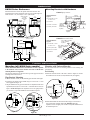
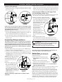
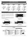
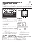
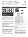
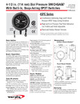
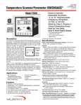
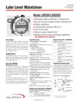
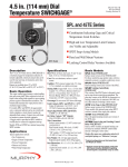
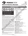
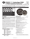
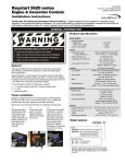
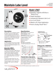
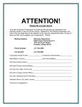
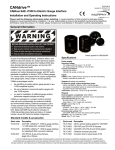
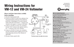
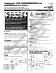
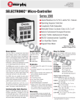
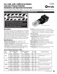
LM-92164N
Revised 10-03
Section 15
Installation Instructions for Level Maintainers
(00-02-0176)
Model Series LM300
Read the following instructions before installing. A visual inspection of this product for
damage during shipping is recommended before mounting. These installation instructions are
intended for all LM300 series models.
GENERAL INFORMATION
LM301-EX
Shown with optional hose kit fittings
WARNING
BEFORE BEGINNING INSTALLATION OF THIS MURPHY PRODUCT
✔
✔
✔
✔
Disconnect all electrical power to the machine.
Make sure the machine cannot operate during installation.
Follow all safety warnings of the machine manufacturer.
Read and follow all installation instructions.
LM300: Level Maintainer only (no switches).
LM301: Low switch contacts for low level shutdown or
alarm. Four wires, SPDT.
LM302: Two switches for low and high level shutdown or alarm. Four wires,
DPST, wired N.O. in normal operating ranges.
LM303: Two switches for low and high level shutdown or alarm. Four wires,
DPST, wired N.C. in normal operating ranges.
LM304: Two switches. Alarm before shutdown on low level and shutdown on
low-low level. Four wires, DPST, wired N.O. in normal operating ranges.
LM305: Two switches. Alarm before shutdown on low level and shutdown on lowlow level. Four wires, DPST, wired N.C. in normal operating ranges.
Specifications
Case/Cover: Die cast aluminum.
Switch Housing: Aluminum.
Approval Rating: LM301 thru LM305 : CSA certified†† for non hazardous
locations. Enclosure Type 4 certified.
LM301-EX thru LM305-EX: CSA certified†† for Class I, Groups C and D;
Class II, Groups F and G hazardous locations. Enclosure Type 4 certified.
Float: Rigid polyurethane foam. Polyurethane coated.
Maximum Ambient Temperature: 250°F (121°C)
Oil Inlet Connection: Top entry 1/2-14 NPT with built-in filter screen (removable
for cleaning).
Inlet Orifices: 1/4 in. (6 mm) standard. 1/8 in. (3 mm) available.
Wire (switch models): 18 AWG x 13 in. (1.0 mm2 x 330 mm).
Maximum Inlet Pressure (MIP):
Max. Differential: 2 in. (51 mm) between running and stationary oil level.
30 psi (207 kPa) [2.07 bar].
with 1/8 in. (3 mm) orifice.
15 ft. oil (4.6 m oil)
with 1/4 in. (6 mm) orifice.
Maximum Case Pressure (MCP): 15 psi (103 kPa) [1.03 bar].
Orifice Seal†: Buna-N Thumb-Valve™
Switch Contact: Silver, SPDT snap acting, 10A @ 125, 250VAC; 10A @ 30VDC.
(1 only for low level; 2 only for high & low; or 2 only for low with alarm before shutdown)
**
Patent
5493086
Outlet Connection: 3/4-14 NPT left side, right side, and bottom.
Crankcase Balance Vent Fitting: 1/2-14 NPT.
Mounting: Accepts Murphy pipe mounting or universal mounting brackets.
Lens: Clear “Frog Eye” non-staining, high impact, high temperature nylon; UV
and heat stabilized.
Dial: High visibility white background with green and white “index” lines for
normal level indication.
Test Knob: Rotate to test switch operation. Turn clockwise for low level test
and turn counterclockwise for high level test.
Flow Rate Test: Using SAE 30 @ 32°F (0°C).
Orifice
Flow Rates
Pressure
Diameter
4 ft. oil – 15 ft. oil 4.7 GPH - 31.0 GPH
1/4 in.*
(6 mm) (1.2 m oil – 4.6 m oil) (17.8 LPH - 117.3 LPH)
10 psig – 30 psig
1/8 in. (68.9 kPa – 207 kPa) 16.9 GPH - 32.1 GPH
(3 mm)
[.69 – 2.07 bar] (63.7 LPH - 121.5 LPH)
*Standard
NOTE: Friction losses due to piping NOT considered.
Optional Hose Kit: 15000355
Quantity Description
1
1
2
2
2
2
1/2 in. (13 mm) I.D. x
3 ft. (914 mm) long hose
1 in. (25 mm) I.D. x
3 ft. (914 mm) long hose
1/2 in. (13 mm) worm gear clamp
1 in. (25 mm) worm gear clamp
1/2 NPT x 1/2 in. (13 mm) barbed fitting
3/4 NPT x 1 in. (25 mm) barbed fitting
††CSA certified with switch contacts rated at 10 A @ 250 VAC (standard).
** Products covered by this bulletin comply with EMC Council directive
89/336/EEC regarding electromagnetic compatibility except as noted.
LM-92164N page 1 of 4
DIMENSIONS
LM300 Series Enclosures
Mounting Brackets with Hardware
The dimensions below are for the optional -EX model enclosure. The
standard model enclosure dimensions are the same except the height and
width which are: 7 in. (178 mm) H, 7-7/8 in. (200 mm) W.
Oil Inlet Connection*
1/2-14 NPT
with removable
screen
Crankcase
Vent
1/2-14 NPT
6 in.
(152 mm)
Electrical
Conduit
1/2-14
NPT
15000371 pipe bracket
5.20 in.
(132 mm)
Additional Hardware
Supplied
(4) 3/8-16 UNC x 1 inch
(25 mm) screws
4.50 in.
(114 mm) Hole .88 in.
(22 mm) dia.
(4) 3/8-16 nut
(4) 3/8 I.D. lock washer
(2) 3/8 I.D. flat washer
Test
Knob
.376 in.
(10 mm)
minimum
bottom surface
2 places
2.50 in.
(64 mm)
1/4-20 NC
2 places
8-1/4 in.
(210 mm)
*Applies to level maintaining models only.
Monitoring Port Connection
3 places, 3/4-14 NPT
15000370 universal bracket
7-3/16 in.
(183 mm)
Slot, .390 in. (10 mm)
Additional Hardware
x 2 in. (51 mm)
Supplied
4 places
(2) 3/8-16 UNC x 1 inch
(25 mm) screws
Slot, .390 in. (10 mm)
in. (120 mm)
(4) 3/8 I.D. flat washer x3 4.71
places
Snap Switch
Case Assembly
5-15/16 in.
(151 mm)
(17 6.69
0 m in.
m)
.
5 in
1.7 mm)
(44
(2) 3/8 I.D. lock washer
(11 4.50
4 in
(13 5.19 mm) .
2 m in.
m)
3/8-16
UNC-2B
Mounting
Holes, 2 places
2-3/4 in.
(70 mm)
(1 7.5
91 0
i
m n.
m
)
(2) 3/8-16 nut
5-3/16 in.
(132 mm)
TYPICAL INSTALLATION
Mounting (all LM300 Series models)
Mounting with Universal Bracket
NOTE: Mount the LM300 series level maintainers as close as possible
to the crankcase. Also, excessive vibration can cause overfill. Be sure
mounting brackets are supported.
The following instructions are based on the usage of the pipe and universal
mounting brackets shown above.
The universal bracket has two mounting methods: deck mounting and
pan mounting.
Deck Mounting
1. Install the universal bracket to the deck as shown in Figure 2A with two
flat washers and two 3/8 inch (10 mm) diameter bolts (not supplied).
Pipe Bracket Mounting
1. Mount a nominal 1/2 inch (21 mm) diameter pipe to the deck of the engine.
2. Install the pipe bracket to the LM300 using two 3/8-16 UNC x 1 inch
bolts supplied. See Figure 1A.
3. Slip the LM300 onto the pipe and install the two adjustment bolts. Each
adjustment bolt consists of a 3/8-16 UNC x 1 inch bolt and two nuts. See
Figure 1B. DO NOT tighten the adjustment screws too tightly because
you will have to adjust the LM300 later in the installation process.
Crankcase
Universal
Bracket
Deck
Pipe
Bracket
Threaded
hole
Figure 2A
Adjustment
Bolts
LM300
Figure 1A
Pipe
Crankcase
Adjustment
Bolts
Figure 2B
2. Mount the LM300 to the universal bracket using two 3/8-16 UNC x 1
inch (25 mm) bolts supplied (Figure 2B). DO NOT tighten the
adjustment screws too tightly. You will have to adjust the LM300 later in
the installation process.
Figure 1B
LM-92164N page 2 of 4
TYPICAL INSTALLATION continued
Crankcase (Oil Pan) Mounting
1. Install the universal bracket to the crankcase using the existing
crankcase bolts (Figure 3A). Crankcase bolt diameter must be no larger
than 7/16 inch (11 mm).
Connecting the LM300 to an Oil Supply Tank
(level maintaining models only)
Crankcase
Bolt
Universal
Bracket
Note Clearance
before mounting
4. Fill the crankcase to the proper oil levels. With the engine running and
warm, loosen the mounting bracket adjustment bolts and adjust the
LM300 so that the oil level in the sight gauge is aligned with the white
“index line” on the dial (Figure 4). Tighten the adjustment bolts securely.
Crankcase
Adjustment
Bolt
Figure 3A
Figure 3B
NOTE: Check clearance between crankcase and mounting bracket
before installing the mounting bracket. If space between the crankcase
and mounting bracket does not allow installation and access to the
adjustment bolts advance to Step 3.
2. Mount the LM300 to the universal bracket using two 3/8-16 UNC x 1
inch bolts supplied. DO NOT tighten the adjustment bolts too tight. You
will have to adjust the LM300 later in the installation process.
3. If space between the crankcase and mounting bracket is narrow, install
the universal mounting bracket to the LM300 before installing to the
crankcase oil pan.
Connecting Fittings and Hoses
The following instructions are for all LM300 series level maintainers.
All steps that reference oil inlet or oil supply tank DO NOT apply to
non-level-maintaining models. Also, these instructions are based on the
Murphy optional hose kit described on page 1. If you did not order the
optional hose kit, gather the hoses, clamps and fittings as specified in
the optional hose kit.
1. Install the LM300 fittings in their proper locations. NOTE: Apply a
sealant such as teflon, to all threaded connections.
2. Attach the 1 inch (25 mm) diameter, flexible monitoring hose to the
crankcase and the monitoring port on the LM300. See Figure 4.
CAUTION: The hose must slope slightly downward from the LM300
and MUST NOT have any droop or low spots.
NOTE: If the drain plug on the crankcase
is used for the connection, we
recommend installation of a tee to
Oil Inlet
Vent Hose
allow draining of the crankcase
Hose
for service.
Viewing
Running
3. Install the 1/2 inch (13 mm)
Lens
Engine
I.D. x 3 ft. (914 mm) hose to
Crankcase
Oil Level
the vent connection on the
LM300 to the vent connection
on the crankcase. See Figure 4.
Monitoring Hose
The vent connection on the
crankcase must be well above the
regulated oil level. All hoses must
Figure 4
be clear of obstructions.
BEFORE CONTINUING, VERIFY THAT ALL HOSE CLAMPS
ARE TIGHT.
1. Remove the caplug from the oil inlet connection. Be sure the filter, inside
the connection, is clear of debris. Install the oil inlet connection.
2. Connect a 1/2 inch I.D. (13 mm) or larger hose
Oil Supply
to oil inlet fitting on the LM300 and to the shutoff
Tank
valve on the oil supply tank. See Figure 5. For
models LM300 thru LM305 recommended
minimum mounting of the oil supply
Oil Inlet
tank above the LM is 4 ft. (1.2m);
Hose
maximum 15 ft. (4.6m). The
hose must maintain a
downward slope and not have
low spots or droops.
Maximum head pressure
rating using standard 1/4 in. (6
mm) orifice is 15 ft. (4.6
meters). See Flow Rate test on
page 1 for additional orifice pressure
ratings.
Figure 5
3. Before filling the supply tank with
oil, be sure the tank is clean and dry andthe shutoff valve is closed.
Also, be sure all hoses and clamps are tight. Fill the tank with CLEAN
oil.
WARNING: Overfill condition can be caused by excessive
inlet pressure, (maximum inlet pressure depends on orifice),
and/or improper “vent to crankcase” installation.
See Flow Rate Test on page 1 for maximum pressure.
4. After oil supply tank is full, open the shutoff valve.
Next, make the proper electrical connections for the application. See
contact ratings on page 1 and schematics on page 4.
Switch Test (switch models only)
To test the shutdown and/or alarm functions
perform the following:
1. Unscrew protective boot from test knob.
IMPORTANT: Always replace boot after
testing.
2. Turn the test knob 1/4 turn to the right
(clockwise), for low test indication (Figure 6).
Figure 6
3. Turn the knob 1/4 turn to the left
(counterclockwise), for high test indication. DO NOT FORCE
THE TEST KNOB TO TURN.
NOTE: After the engine shuts down, you will notice that the oil in the
sight gauge glass will rise above normal running level, possibly
showing an overfill condition. This is a result of “drain-back” to the
engine crankcase and it is normal. Therefore, on models LM302 and
LM303 it may be necessary to wire the high level shutdowns into a
class “B” or “C” (bypass until first time safe) lockout, so as to allow a
permissive start. After the engine is re-started the level will pull down
to the normal running level and the shutdown features will be active. A
modulating valve (Thumb-Valve™) in the level maintaining models
will allow oil usage to be made-up continuously during operation.
LM-92164N page 3 of 4
SWITCH WIRING DIAGRAMS
WARNING: DISCONNECT ALL ELECTRICAL POWER BEFORE CONNECTING ANY WIRES.
LM301
SPDT
LM302
High/Low N.O.
DPST
Green
Green
Black
Black
Normal
Yellow
LM303
High/Low N.C.
DPST
Red
Green
High
Normal
Normal
Normal
Low
Brown
Yellow
Normal
Red
Float
Normal
Normal
Orange
Yellow
Blue
Low
Orange
Low
Red
Low
Low
Low-Low
Low-Low
High
Blue
Normal
Brown
Normal
Low
Black
Low
High
Float
Green
Green
High
Low
Low
LM305
Alarm before
shutdown N.C.
DPST
LM304
Alarm before
shutdown N.O.
DPST
Low-Low
Low-Low
Float
Float
Float
OPERATING RANGES OF SWITCHES
This section applies only to models that have built-in switches. The illustrations
below and to the right show the dials and their operating ranges of the switches.
If levels are within the designated zones the switch(es) will activate. Notice that
a switch is capable of activating approximately 3/8 in. (10 mm) from the top of
the high zone and 3/8 in. (10 mm) from the bottom of the low zone. The dial in
Figure 9 shows that if level continues to drop into the low-low zone, a
shutdown will occur.
3/8 in.
(10 mm)
3/4 in.
(19 mm)
Normal
Operating Range
3/4 in.
(19 mm)
NOTE: Color zones on dial face show approximate normal operating zones.
Actual conditions may vary depending upon operating characteristics of the
engine. Placement of the LM300 according to the above instructions will
compensate for these conditions.
Normal
Operating Range
High Zone
Shutdown or Alarm
3/4 in.
(19 mm)
Low Zone
Shutdown or Alarm
3/8 in.
(10 mm)
Figure 8: LM302/LM303
Normal
Operating Range
3/4 in.
(19 mm)
Low Zone
Shutdown or Alarm
Low Zone Alarm
Low-Low Zone Shutdown
3/8 in. 1/4 in.
(10 mm) (6 mm)
3/8 in.
(10 mm)
Figure 7: LM301
Figure 9: LM304/LM305
Warranty
A limited warranty on materials and workmanship is given with this FW Murphy product.
A copy of the warranty may be viewed or printed by going to www.fwmurphy.com/support/warranty.htm
GI
D
MURPHY SWITCH OF CALIFORNIA
41343 12th Street West
Palmdale, California 93551-1442; USA
+1 661 272 4700 fax +1 661 947 7570
e-mail [email protected]
www.murphyswitch.com
MACQUARRIE CORPORATION
1620 Hume Highway
Campbellfield, Vic 3061; Australia
+61 3 9358 5555 fax +61 3 9358 5558
e-mail [email protected]
E
MURPHY DE MEXICO, S.A. DE C.V.
Blvd. Antonio Rocha Cordero 300, Fracción del Aguaje
San Luis Potosí, S.L.P.; México 78384
+52 444 8206264 fax +52 444 8206336
Villahermosa Office +52 993 3162117
e-mail [email protected]
www.murphymex.com.mx
FRANK W. MURPHY, LTD.
Church Rd.; Laverstock, Salisbury SP1 1QZ; U.K.
+44 1722 410055 fax +44 1722 410088
e-mail [email protected]
www.fwmurphy.co.uk
RE
FW Murphy
P.O. Box 470248
Tulsa, Oklahoma 74147 USA
+1 918 317 4100
fax +1 918 317 4266
e-mail [email protected]
www.fwmurphy.com
CONTROL SYSTEMS & SERVICES DIVISION
P.O. Box 1819; Rosenberg, Texas 77471; USA
+1 281 633 4500 fax +1 281 633 4588
e-mail [email protected]
STER
USA–ISO 9001:2000 FM 28221
UK–ISO 9001:2000 FM 29422
In order to consistently bring you the highest quality, full featured products, we reserve the right to change our specifications and designs at any time.
Printed in U.S.A.
LM-92164N page 4 of 4