1
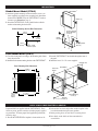
ST-94112N
Revised 07-04
Section 25
Installation and Operation Instructions for
SELECTRONIC® TATTLETALE® Annunciator
Model ST8
(00-02-0758)
Please read the following information before installing. A visual inspection of this product for damage during shipping is recommended before mounting. It is your responsibility to have a qualified person install this unit and make sure it conforms to
NEC and local codes.
GENERAL INFORMATION
WARNING
BEFORE BEGINNING INSTALLATION OF THIS MURPHY PRODUCT
✔
✔
✔
✔
Disconnect all electrical power to the machine.
Make sure the machine cannot operate during installation.
Follow all safety warnings of the machine manufacturer.
Read and follow all installation instructions.
Certain danger to human safety and to equipment may
occur if some equipment is stopped without pre-warning.
It is recommended that monitored functions be limited to
alarm-only or to alarm before shutdown.
Specifications
Description
The ST8 is an eight point TATTLETALE® panel designed to give “first out”
indication of cause of alarm or shutdown. This “first out” feature means
that only the first fault will be shown by LED; this feature isolates the
primary cause of shutdown, and helps simplify troubleshooting. The
ST8 is available in two different types of mounting: flush mounting
(“F”), and gimbal mounting (“G”).
All specifications apply to both models unless indicated.
Power Input (Operating Voltage): 8–32 VAC, 8–40 VDC
Sensor Inputs: 8 sensor switches, normally open or
normally closed dry contacts.
Number of Alarm Points: ST8: 8 first out shutdown/alarm.
Lockout Time Delay During Startup:
25 to 35 seconds (selectable for each sensor input).
DIMENSIONS
ST8-F
5-11/16 in.
(144 mm)
ST8-G
2-7/8 in.
(73 mm)
Clearance
2-3/16 in.
(56 mm)
6-3/8 in.
(162 mm)
5-7/8 in.
(149 mm)
5-3/8 in.
(137 mm)
ST-94112N page 1 of 4
Gimbal
Mounting
Bracket
1-3/4 in.
(44 mm)
MOUNTING
Gimbal Mount Model (ST8-G)
TATTLETALE®
1. Install the gimbal mounting bracket with three screws (customer supplied) according to the mounting hole dimensions
shown below. NOTE: Verify the TATTLETALE®s rotation
clearance (see Dimensions, page 1).
2. Attach the TATTLETALE® to the gimbal bracket with the
washer and mounting bracket knobs.
Washers (2)
Gimbal Mounting Bracket Hole Dimensions
Customer Supplied
Bracket Mounting
Screws (3)
3-1/2 in.
(89 mm)
1 in.
(25 mm)
1-3/4 in.
(44 mm)
Gimbal
Bracket
Mounting Bracket
Knobs (2)
9/64 in. (4 mm)
diameter 3 places
Panel Mount Model (ST8-F)
1. Cut a hole in the panel according to the mounting hole dimensions shown below.
2. Install the flush mount mounting bracket on the TATTLETALE®.
3. Insert the TATTLETALE® into the hole through the front of
the panel.
4. Install the four 6-32 x 5/8 screws supplied.
Mounting Holes
Panel Mounting Hole Dimensions
TATTLETALE®
Flushmount
Bracket
5-5/16 in.
(135 mm)
5-3/4 in.
(146 mm)
5-3/8 in.
(137 mm)
5/32 in.
(4 mm)
Typical
4 places
4-11/16 in.
(119 mm)
Bracket Mounting
Screws (2)
Mounting
Screws (4)
APPLYING PREPRINTED LABELS
Preprinted label are supplied with the TATTLETALE®. These
labels are precut, pressure sensitive and when properly applied
are permanent. To insure proper label application perform the
following steps:
1. Be sure the TATTLETALE®s faceplate is clean and free of oil.
2. Peel one label at a time and position on the faceplate in the
box which matches the input sensor position.
3. Before pressing down, be sure label is correctly placed.
4. Press firmly on the label, and leave untouched for
several hours.
ST-94112N page 2 of 4
ELECTRICAL
metal link must be removed to use this wiring. When the switch
opens the shutdown/alarm will be initiated.
Figure 3 shows the wiring for a N.O. SWICHGAGE® which is the
same as Figure 1 except two wires are run from terminals A and B to
the SWICHGAGE®. This Closed Loop™ wiring circuit monitors the
wires as well as the switch. If the circuit is opened due to a loose
connection or broken wire or the SWICHGAGE® closes, the shutdown/alarm circuit will be initiated.
Figure 4 shows the ST8 internal SPDT relay in the “run” or operating mode.
The Figures below show typical customer switch wiring for the ST8.
Switch wiring should be run separately from other wires; DO NOT
route switch wires with AC power wires since voltages, that may
be induced into the switch wires, may exceed rating and cause
damage to circuits or cause false trips.
Figure 1 shows the wiring for a normally open (N.O.) SWICHGAGE® connected between terminal B and the negative power input.
A metal jumper is connected between A and B. When the SWICHGAGE® closes the shutdown/alarm circuit will be initiated.
Figure 2 shows the wiring for a normally closed (N.C.) switch
connected to input terminals A and B. The factory installed
A
A
B
B
Figure 1: Typical N.O.
Sensor Connection
9
10
11
N.O.
N.C.
C
A
B
Figure 2: Typical N.C.
Sensor Connection
Figure 3: Typical N.O.
Closed Loop™ Sensor Connection
Figure 4: Internal Relay
Circuit
Typical Wiring
Below is a typical wiring diagram for the ST8 TATTLETALE®.
To Hold Coil
Start
Pushbutton
Flyback
Diode
Flyback Diode
To Battery +
Flyback
Diode
To Pull-in Coil
Starter
Motor
Flyback
Diode
Push/Pull Solenoid
Slave Relay
Solenoid Valve
NOTE: Connect only one shutdown
device to the ST8. Wiring
for Push/Pull Solenoid, Solenoid Valve
and Slave Relay shown for clarity only.
2 Amp
Fuse
Engine Oil
Pressure
Internal Relay
(shown in
run mode)
Engine Water
Temperature
ST8
Shutdown
Sensor Inputs
A
B
A
B
Low
Water
Level
13 14
Run
9 10 11 12
A
B
A
B
1
5
6
2
7
3
8
4
A
ON/OFF
Switch
Battery
Remove jumper from
terminals 12 and 13 and
set individual sensor Lockout
Switch for a 25 to 35 second
lockout time delay during
startup (see page 4
Setting Lockout Switches).
Jumper Wire
(customer supplied)
B
A
B
A
B
ST8
Shutdown
Sensor Inputs
A
B
No Connection
No Connection
ON
No Connection
Coil
1 2 3 4 5 6 7 8
Differential
Pressure
Sensor Lockout Switches
ST-94112N page 3 of 4
No Connection
Distributor
BASIC OPERATION
ST8
Setting Lockout Switches
1. Apply power to the ST8 TATTLETALE® (terminals 13 and 14).
2. The “POWER ON” and “RUN” LED light will switch On. The
“POWER ON” LED indicates power has been applied to the ST8.
The “RUN” LED indicates the internal relay is in the
operating mode.
3. The lockout time delay during startup will begin timing. Sensors with
lockout time delay selected (see Setting Lockout Switches below) will
not trip alarm or shutdown circuit until time delay times out (25-35
seconds). If lockout switches are not set there will not be a time
delay during startup.
4. The 8 Red shutdown LEDs are for shutdown indication (see
Figure 6).
5. When a shutdown signal is received from a SWICHGAGE®, the
shutdown LED will light and internal shutdown relay will switch to
activate a shutdown device (see Typical Wiring page 3). All other
shutdown sensor inputs are locked out.
6. Shutdown LED will remain on even if conditions return to normal.
To clear the LED, power must be removed or push button reset
is operated.
Lockout switches allow you to lockout shutdown/alarm sensors during
startup. For instance, on a pressure SWICHGAGE®, the lockout time
delay allows time for pressure to build up thus lifting the pointer off the
low limit contact. If the lockout time delay is not set the TATTLETALE® will initiate the shutdown/alarm sequence.
Each sensor input on the ST8 has a lockout
time delay at startup with a length of 25 to
Lockout
35 seconds.
Switches
1. Locate the lockout switches on back
ON
of the unit (see Figure 7).
2. Determine which sensors you wish
1 2 3 4 5 6 7 8
to lock out. Switch the corresponding
On back
of unit
sensor lockout switch “ON”. A SENSOR CAN BE LOCKED-OUT
Figure 7
ONLY WHEN ITS LOCKOUT
SWITCH IS SWITCHED “ON”.
3. Remove the jumper between terminals 12 and 13. This will activate
the time delay. If this jumper is not removed the lockout time delay
will not function.
Warranty
A limited warranty on materials and workmanship is given with this FW Murphy product.
A copy of the warranty may be viewed or printed by going to www.fwmurphy.com/support/warranty.htm
GI
D
MURPHY SWITCH OF CALIFORNIA
41343 12th Street West
Palmdale, California 93551-1442; USA
+1 661 272 4700 fax +1 661 947 7570
e-mail [email protected]
www.murphyswitch.com
MACQUARRIE CORPORATION
1620 Hume Highway
Campbellfield, Vic 3061; Australia
+61 3 9358 5555 fax +61 3 9358 5558
e-mail [email protected]
E
MURPHY DE MEXICO, S.A. DE C.V.
Blvd. Antonio Rocha Cordero 300, Fracción del Aguaje
San Luis Potosí, S.L.P.; México 78384
+52 444 8206264 fax +52 444 8206336
Villahermosa Office +52 993 3162117
e-mail [email protected]
www.murphymex.com.mx
FRANK W. MURPHY, LTD.
Church Rd.; Laverstock, Salisbury SP1 1QZ; U.K.
+44 1722 410055 fax +44 1722 410088
e-mail [email protected]
www.fwmurphy.co.uk
RE
FW Murphy
P.O. Box 470248
Tulsa, Oklahoma 74147 USA
+1 918 317 4100
fax +1 918 317 4266
e-mail [email protected]
www.fwmurphy.com
CONTROL SYSTEMS & SERVICES DIVISION
P.O. Box 1819; Rosenberg, Texas 77471; USA
+1 281 633 4500 fax +1 281 633 4588
e-mail [email protected]
STER
USA–ISO 9001:2000 FM 28221
UK–ISO 9001:2000 FM 29422
In order to consistently bring you the highest quality, full featured products, we reserve the right to change our specifications and designs at any time.
Printed in U.S.A.
ST-94112N page 4 of 4