1
Owner's
ingersoll
IMPORTANT
INFORMATION!
READ
Manual
Installation, Operation and Maintenance
Instructions for Models SS3 and SS5
Stationary Air Compressors
AND FOLLOW
THESE
INSTRUCTIONS.
RETAIN
FOR REFERENCE.
ll_*-]r-1=1ul li"
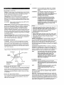
DEFINITIONS
/k_
WILL cause DEATH, SEVERE INJURY or substantial
property damage
WARNING
CAN cause DEATH, SEVERE INJURY or substantiaI
property damage,
CAUTION
WILL or CAN cause MINOR INJURY or property
damage.
GENERAL
,_ _
WARNING
SAFETY
PRECAUTIONS
@ An air pressure regulator
toot or accessory
to adjust the alr pressure enlering
•
An air line fitter for removal of moisiure and oil vapor in
compressed air
•
An in-line lubricator
the
to prolong lhe life of air tools.
iNTAKE AIR, Can contain carbon monoxide or other
contaminants. Will cause serious injury or death
ingersoll-Rand air compressors are not designed,
intended or approved for breathing air Compressed
air should not be used for breathing air applications
unless treated in accordance with all applicable
codes and regulaUons,,
ql, Separate air transformers which combine the !'unctions of air
regulation andlor moisture and dirt removal
HAZARDOUS VOLTAGE Can cause serious injury
or death. Disconnect power and bteed pressure
from tank before servicing Lockout/Tagout
machine. Compressor must be connected to
properly grounded circuit See grounding
instructions
in manuat, Do not operate compressor
tn wet conditions,, Store indoors
Ensure adequate lifting equipment
moving your unit to the inslaIlatton
MOVING PARTS, Can cause serious injury Do not
operate with guards removed. Machine may start
automatically
Disconnect power before servicing_
Lockout/Tagout machine,,
HOT SURFACES, Can cause serious
touch Allow to cool before servicing
hot compressor or tubing
r DO not
Do not touch
injury,
HIGH PRESSURE AIR. Bypassing_ modifying or
removing safety/relief valves can cause serious
injury or death, Do not bypass, modify or remove
safety/relief valves Do not direct air stream at body.
Rusted tanks can cause explosion and severe injury
or death Drain tank daily or after each use. Drain
valve located at bottom of tank.
z_ CAUTION
Your air compressor unitis suitable for operating air too_s, caulking
guns, grease guns, sandblasters, etc Depending on your
application, the following accessories may be required:
RISK OF BURSTING. Use only suitable air handling
parts acceptable for pressure of not less than the
maximum allowable working pressure of the
machine.
© IngersolL-Rand
Printed in U S A
Company
Cenlact your nearest authorized dealer or cal! 1-800-AIR-SERV for
more information on air toots and accesser}as for your application
NOTE:
is available
site
for unloading and
Lifting equipment must be property rated for the
weight of the unit.
Lift the unit by the shipping skid only,, Use straps to
prevent tipping
Lk CAUTION
Do not work on or walk under the compressor
it is suspended,
while
Be[ore signing the deliveryreceipl,
inspecl for damage and missing
parts If damage or missing parts are apparenL make the
appropriate notation on the delivery receipt, then sign the receipt.
Immediately contact the carrier for an inspection. All material must
be held in the receiving location for the carrier's inspection Deiivery
receipts that have been signed without a notation of damage or
missing parts are considered to be delivered "clear" Subsequent
claims are then considered to be concealed damage claims SeUle
damage claims directly with the transportation company
Lf you discover damage after receiving the unit (concealed
damage), the carrier must be notified within 15 days of receipt and
an inspection must be requested by telephone with confirmation in
writing On concealed damage claims, the burden of establishing
that the unit was damaged in transit reverts back to the claimant
Read lhe unit specification labei to verify it is the mode! ordered.
and read the meier nameplate to verify il is compatibJe with your
e_ectrical conditions Make sure electrical enclosures and
componenls are appropriate for your applicafion
Form SCD-B77A
March 2002
-...........
SELECTING
A LOCATION
GENERAL° Select a clean, dry, welt-lighted indoor area with plenty
of space far proper cooling air flow and accessibility. Locate the unit
at least 12 inches (30 cm) from wails, and make sure the main
power supply is clearly identified and accessible
TEMPERATURE.. Ideal operating temperatures are between 32"F
and 100°F (0°C and 37.B_C) If temperatures consistently drop
below 32°F (0"C), locale the unit inside a heated building !f th_s is
not possible, you must protect safety!relief valves and drain valves
from freezing
CAUTION
Never operate in temperatures
or above 125°F (5t.0°C)..
NOISE CONSIDERATIONS
Consull local officials [or information
regarding acceptable noise levels in your area To reduce excessive
noise, use vibralion isolator pads or intake silencers, relocate the
unit or construct total enclosures or baffle waits
MOUNTING
WARNING
Remove the unit from the skid before mounting..
The unit must be permanently mounted When mounting the unit.
bait the feet to a firm. fevel foundation (such as a concrete floor)
Do not bolt uneven feet tight}y to the foundation, as this will cause
excessive stress on the receiver tank Use metal shims under the
"short" feet if necessary
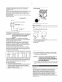
Typical Permanent
Do net use plastic pipe, rubber hose, or lead4in
soldered joints anywhere in the compressed air
system
,_.WARNING
If an afteroeoler, check valve, block vafve, er any
other restriction is added to the compressor
discharge, install a properly*sized ASME approved
safetytrelief valve between the compressor
discharge and the restriction.
z_ CAUTION
If you will be using Ingerso!l-Rand synthetic
compressor lubricant, all downstream piping
material and system components must be
compatible
Refer to the following material
compatibility list If there are incompatible materials
present in your system, or if there are materials net
included in the Hst, contact your dealer or cab
1 =800-AIR-SERV.
below 20°F (_6.6°C)
HUMID AREAS. In frequently humid areas, moisture may form in
the bare pump and produce sfudge in the lubricant, causing running
parts to wear out prematurely
Excessive moisture is especially
likely to occur if the unit is located in an unheated area that is
subject to large temperature changes Two signs of excessive
humidity are external condensation on the bare pump when it cools
down and a "_mllky_ appearance in petroleum compressor lubricant
You may be able to prevent moisture from forming in the bare pump
by increasing ventilation, operating for longer intervals or installing
a crankcase heater kit
PERMANENT
_ WARNING
Mounting (Customer.Supplied
Hardware)
Suitable:
Viton®, Teflon@', Epoxy (Glass Fltied), O_1Resistant A_kyd, Fluorostllcone.
Fluorocarbon, Polysulflde, 2-Component Urethane, Nylon, DeSrln®.
Celcon®, High Nltrtle Rubber (Bane N NBR mare than 36% Aerylonltrlle).
Polyurethane, Polyethylene, Eplchtorohydr|n,
Polyac_late.
Melamine.
Potyprepylene, Baked PhenoIIce. Epoxy. Modified Alkyds
{® indicates trademark of DuPont Corporation)
Not Recommended:
Neoprene, Naturai Rubber, SBR Rubber. Acrylic Paint. Lacquer, Varnish.
Polystyrene, PVC, ABS. Poiycarbenate. Cellulos_ Acetate, Low Nttrtle
Rubber (Buna N. NBR less than 36% Actylonttdle),
EPDM, Ethylene Vinyl
Acetate, Latex. EPR. Acrylics, Phenoxy Polysalfones. Styrene
Aorylenitrlte (San), Butyl
GENERAL REQUIREMENTS.. The piping, fittings, receiver tank.
etc must be certified safe for at least Ihe maximum working
pressure of the unit Use herd-welded or threaded steel or copper
pipes and cast iron fittings that are certified safe for the unit's
discharge pressure and temperature DO NOT USE PVC PLASTIC
Use pipe thread sealant on all threads, and make up joints tightly to
prevent air feaks
CONDENSATE DISCHARGE PIPING If inslalltng a condensate
discharge line, the piping must be at Ieast one size larger than the
connection, as short and direct as possible, secured tighBy and
routed to a suitable drain point Condensate must be disposed of in
accordance wffh local, state, and federal laws and regulations
NOTE
Fiat Washer
3/8" Lag Screw
Isofator
\
Shlm beneath
ELECTRICAL
_, WARNING
Floor Jlne
isotater washer, if
necessary
Lag screw anchor
for concrete
CAUTION
THE A!R INLET
FILTER
Do not operate the unit without the air inlet filter(s).
If the air around the unit is relatively free of dirt, instant the air inter
filter(s) at the inlet conneclion(s) at the bare pump. If remote air
inlet piping or heavy duty filtration is required, contact your dealer
for information
INSTALLING
DISCHARGE
PIPING
If it is necessary to install air discharge and condensate discharge
piping, adhere to the following genera{ guidelines Conlact your
dee]or for more _nformation
WIRING
Electrical installation and service shoutd be
performed by a qualified electrician who is familiar
with all applicable loca!, state and federal laws and
regu}attons r
NOTE
INSTALLING
All compressed air systems generate condensate
which accumulates In any drain point (e.go tanks,
filters, drip legs, affercoolers, dryers). This
condensate contains lubricating oil and/or
substances which may be regulated and must be
disposed of in accordance with local, state, and
federal laws and regulations..
This product should be connected to a grounded,
metallic, permanent wiring system, or an
equipment-grounding
terminal or lead on the
product.
GENERAL The motor rating, as shown on the motor nameplate,
and the power supply must have compatible voltage, phase and
hertz characleristics
WIRE SIZE. The electrical wiring between the power supply and
electric motor varies according to motor horsepower Power leads
must be adequately sized to protect against excessive voltage drop
during start-up Information for selecting the proper wire size and
securing conneclions should be provided with the motor If not. refer
to the National EIeclric Code (NEC) or applicable local, stale and
federa_ laws and regulations. If other electrical equipment is
connected to the same circuit, the total electrica! load must be
considered in selecting the proper wire size DO NOT USE
UNDERSIZE WIRE
FUSES., Refer to the National Electric Code
fuse or circuit breaker rating required. When
remember the momentary starting current of
greater than its full load current Time-delay
are recommended.
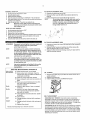
Single-Phase
Filling Procedures
to determine the proper
selecting fuses,
an electric motor is
or "slow-blow" fuses
Wiring
T = Supply Line Terminal
L = Load Terminal
uJ
L=J
L1
Pressure switch
INITIAL
START-UP
Follow this procedure
time:
used disconnecLor clrcu_t
breaker
(inctltde_ on/auto-off switch)
Singie phase
m_or
t.
before putting the unit into service for the first
Set the pressure swffch lever to "OFF"..
Pressure Switch Lever
COMPRESSOR
CAUTION
LUBRICATION
Do not operate without lubricant or with inadequate
lubricant. Ingersoll-Rand fs not responsible for
compressor failure caused by inadequate
lubrication
SYNTHETIC LUBRICANT.
We recommend thgersolI-Rand
synthetic compressor lubricant from start-up See the WARRANTY
section for extended warranty information
ALTERNATE LUBRfOANTS. You may use a petroleum-based
lubricant that is premium quality, does not contain detergents,
contains only anti-rust, anti-oxidation, and anti-foam agents as
additives, has a fieshpoint of 440°F (227°C) or higher, and has an
auto-ignition polnt of 650=F (343°C) or higher
OFF"
2.
ON/AUTO
Open the service valve fully to prevent air pressure from building in
the tank. (A=Open, B=Closed)
Service Valve
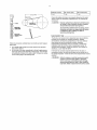
See the petroleum lubricant viscosity table below The table is
intended as a general guide only Heavy duty operating conditions
require heavier viscosities,, Refer specific operating conditions to
_our dealer for recommendations
Temperature Around Unit
_F
40 & below
"C
Vlscosib' @ 100"F (37 8"C)
SUS
Centtstokes
Viscosity Grade
1SO
SAE
4 4 & below
150
32
32
10
40 - BO
4 4 - 26 7
500
t10
!00
30
80 - 125
26.7 - 51.0
750
165
'_50
40
3.
4.
Move the pressure switch lever to "ON/AUTO _ The unit will start
Run the unit for 30 minutes Ensure the service vaive is fully open
and there is no tank pressure build up
CAUTION
you use a petroleum-based
compressor
lubricant
at start-up and
decide
to convert
to Ingersoll-Rand
synthetic
compressor
lubricant
later on, the compressor
valves must be thoroughly
decarbonized
and the crankcase
must be flushed before conversion
FILLING PROCEDURES:
t,, Unscrew and remove the ell fill plug (A)
2. Slowly flit the crankcase with lubricant until the lubricant reaches the
top thread of the sit filI opening and the top of the sight glass
Crankcase capacity for the SS3 Is one-half (0 5) Iiter Crankcase
capacity for the SS5 is one (1) liter.,
3. Replace the oil fill plug HAND TIGHT ONLY
5.,
Unusual noise or vibration indicates a problem Do
not continue to operate until you identify and
correct the source of the problem., IF EMERGENCY
CONDITIONS ARE ENCOUNTERED, SHUT OFF THE
MAIN POWER IMMEDIATELY,
After 30 minutes, close the service valve fully. The air receiver will fill
to cut-out pressure and the motor will stop The unit is now ready for
use
B[o]"J=1:_.,_II[=]h
GENERAL
Your air compressor was designed for f 00% continuous duty
operation with the use of Ingersoll-Rand synthetic compressor
lubricant and 60% continuous duty operation with the use of
petroleum lubricant In other words, synthetic lubricant allows the
compressor to pump continuously without cycling Petroleum
lubricant limits the compressor to a maximum of 36 minutes of
pumping time per hour The compressor should not cycle more than
10 times per hour
NORMAL
1
2
START-UP
FILTER
Set the pressure switch lever to "OFF"
Close the service valve
REPLACEMENT
(SS3)
1.
2.
3 Attach hose and accessory
4., Move the pressure switch lever Io "ON/AUTO _ The coil will start
5. Allow tank pressure to build The motor will stop when tank pressure
reaches cut-out pressure,
6 Open the service valve The unit is now ready for use.
NOTE
When the receiver tank pressure drops below the
factory pro-set minimum, the pressure switch resets
and restarts the unit,
Unscrew and remove the wing nut (A)
Remove the filter cover (B), baffle (C) and e_ement (D) from the
base (E)
3,, install a new efement and reassemble the filter assembly
NOTE
The air intake holes in the baffle and cover must be
staggered t80 _. When reinstalling the assembly at
the inlet connection, ensure the intake hole in the
cover is on the bottom to minimize the entry of
foreign matter from the air
WHEN YOU ARE FINISHED:
1
2
3
4
5
6
Set the pressure switch lever to "OFF"
Close the service valve fully
Remove the air loci er accessory
Slowly open the serv[ce valve to bleed air pressure down Io 20 psig
Slowly open the manual drain valve at the bottom of the tank ta
drain all condensate (water).,
Close the drain valve and the service vaIve for the next use
i
I
II'llI'
' I'
_J
'11I'lll'l
FILTER
WARNING
Disconnect. lock and tag the main power supply and
release air pressure from the system before
performing maintenance.,
NOTE
All compressed air systems contain maintenance
parts (e g, lubricating oil, filters, separators) which
are periodically replaced,. These used parts may be,
or may contain, substances that are regulated and
must be disposed of in accordance with local, state,
and federal laws and regulations.
NOTE
Take note of the positions and locations of parts
during disassembly to make reassembly easier., The
assembly sequences and parts iliusfrated may differ
for your particular unit,,
NOTE
Any service operations not included in this section
should be performed by an authorized service
representative.
ROUTINE MAINTENANCE
Dally or Before
Eacl_ Operation
•
•
•
Monthly
SCHEDULE
Drain receiver tank condensate Open the
manual drain vaive and cofiect and dispose of
condensate accordingly
Check for unusual noise and vibration
Ensure beltguards and covers are securely in
place
• Ensure area around compressor is free from
rags, tools, debris, and flammable or
explosive materials
• Inspect air filter element
Clean or replace if
necessary.
Q Inspec| for air leaks Squirt soapy water
around joints during compressor operation
and watch for bubbles
O
(SS5)
Check lubricant leve_ Fil_ as needed
•
Week{y
REPLACEMENT
1,, Unscrew and remove the wing nut (A) secudng the fitter housing (B)
to its base (C)
2., Remove the filter housing and withdraw lhe old fitler element (D)
Clean the elemen! wilh a jel of air or vacuum
3. Replace the f_ltarelement and housing, securing it in place with the
wing nut previously removed
Check tightness of screws and botts,, Tighten
as needed
Clean exterior
3!500 *
•
Change petroleum lubricant while crankcase
is warm
12/2000 *
•
Change synthetic lubricant while crankcase
warm,
Replace filter element
" Indicates monthslopar_tlng
hours, whichever occurs first;
OIL CHANGE
t.
2.
3.
Remove the oil drain plug (A) and allow lhe lubricant 1o drain into a
suitable container
Replace the oil dra_n plug
Follow the filfing procedures in OPERATION section
BELT ADJUSTMENT
is
CHECKING BELT TENSION Check bell tension occasionaf!y,
especially if looseness is suspected A quick check !o delermine if
adjustment is proper may be made by observing the stack side of
the bait for a slight bow when the unit is in operation if a slight bow
is evident, the belt is usuaily adjusted satisfactorily
TENSIONING BELTS Belt tensioning can be achieved by loosening
the motor anchor screws, pushing the motor away from the pump,
and reiightening tt_e motor anchor screws The motor can be easily
moved by placing a prying toot beneath it. A commercially available
spreader or other belt tensioning device can also be helpS'u1should
tensioning be necessary,
t0.9,
I .0
I 0.o
J
Ensure the pulley and sheave are properly aligned and fhe motor
anchor screws are adequately retightened prior to restarting the
compressor
CAUTION
Improper pulley/sheave alignment and belt tension
can result in motor overload, excessive vibration,
and premature belt andlor bearing failure
To prevent these problems from occurring, ensure
the pulley and sheave are aligned and belt tension
is satisfactory after Installing new belts or
tensioning existing belts
TANK
INSPECTION
The life of an air receiver tank is dependent upon several factors
including, but not ltmlted to, operating conditions, ambient
environments, and Ihe level of matntaoanCer The exact effect of
Follow
the procedures
outlined below to correctfy set and measure
belt tension
1.
2.
Lay e slraight edge across the top outer surface of the belt drive
from pulley to sheave
At the cen_.arof the span. perpendicular !o the bait. apply pressure
to the outer surface of the bell with a tension gauge Force the belt
to the deflection indicated in the table at right Compare the reading
on the tension gauge to the following t.able
these factors on lank life is difficult to predict; therefore,
Ingersoll-Rand recommends that you schedule a certified tank
inspection within the first five years of compressor service. To
arrange a tank inspection, conlacl the nearest _-R Air Center or
distributor, or call 1-800-AIR SERV
if the tank has not been inspected within the first 10 years of
compressor service, the tank must be taken out of service until it
has passed inspection Tanks that fail to meet requirements must be
replaced
_, WARNING
Failure to replace a rusted air receiver tsnk could
result in air receiver tank rupture or explosion,
which could cause substantial property damage,
severe personal injury, or death, Never modifyor
repair tank. Obtain replacement from service centarr
ld
:(0] II :| II:l"l_'[*Ia]l
d I_ [{glm
PROBLEM
m,_
POSSIBLE CAUSE
POSSIBLE SOLUTION
Abnormal piston, ring or
cylinder wear
1 Lubricant viscosity too tow
2 Lubricant level too law
3 Detergent type lubricant being used
4 Cylinder(s) or piston(s) scratched, worn or scored
5 Extremely dusty atmosphere
6 Worn cylinder finish
1
2,
3
4
5
Drain existing lubricant and refill with proper lubricant
Add lubricant to crankcase to proper levet
Drain existing lubricant and refill with proper lubricant
Repair or replace as required
Install remote air inlet piping and route to source of cleaner
air Install
more effective filtration
Air delivery
1
2
3
4
5
Ctogged or dirty inlet and/or discharge line fitter
Atr leaks tn air discharge piping
Lubricant viscosity too high
Compressor valves leaky, broken, carbonized or Ioose.
Piston rings damaged or worn (broken. rough or scratched)
Excessive end gap or side clearance
6 Piston rings not seated, are stuck In grooves or end gaps not
staggered,
7 Cylinder(s) or piston(s) scratched_ worn or scored
8. Defective safety/relief vatve.
1
2
3
4
5
6
7
8
U_it does not come up to
speed
1
Loose beltwheel or motor pulfey, excessive end play in
motor shaft or loose drive belts
2. Lubricant viscosity tea high
3 Improper line voltage
4 Compressor valves leaky, broken, carbonized or loose
S, Defective bait bearings on crankshaft or motor shaft
t Check beflwheel, motor pulley, crankshaft, drive bett ter_sSen
and alignment, Repair or replace as required,
2 Drain existing lubricant and retill wilh proper lubricant
3. Check line voltage and upgrade lines as required Contact
electrician.
4 Inspect valves, Clean or replace as required
Install valve kit
5 Inspect bearings and replace crankshaft assembly If
required,
Unit ts slow Io come up to
speed
1
2,
3,
4
Lubricant vtscosttytoo
high
Leaking check valve or check valve seat blown out
Ambient temperature too low
Bad motor
I
2
3
Unit runs excessively
1,
2
3,
4,
Inadequate venlilation around bettwheel
Drive belts Ioo tight or misaligned
Compressor valves leaky, broken, carbonized
Wrong beltwheel direction of rotation
1
2
3
4
6. Det'_leze cylinder
Excessive
operation
drops off
hot
noise durtng
Excessive starting
stepping
High ellconsumption
and
or loose
t
t
2
3
4
Air leaks te ai_r discharge piping
Pressure switch differential too narrow
Leaking check valve or check valve seat blown out
Excessive condensate tn receiver tank
1
2
t
2
3
4
Clogged or dirty inlet and/or discharge llne triter
Lubricant viscosity toolow
Detergent type lubricant being used
Piston flags damaged or worn (broken. rough or scratched)
Excessive end gap or side clearance
Pislon rings not seated, are stuck tn grooves or end gaps not
staggered
Cylinder(s) or piston(s) scratched, worn or scored
Connecting red, piston pin or crankpin bearings worn or
1
2,
3
4
5,
6
7
8
g
6
7
scored
B Crankshaft seat worn or crankshaft
9 Worn eytinderftnish
scored
kit
Drain existing lubricant end refilt
with proper lubricant
Replace check valve
Relocate unit to warmer environment
Install crankcase healer kit
4. _lace.
1, Loose beltwheel or motor pulley, excessive and play In
meter shaft or loose drive belts
2, Lubricant viscosity too high
3, Lubricant level too few
4 Compressor valves leaky, broken, carbonized or loose
5, Carbon build-up on top of piston(s)
6, Defective ball bearings on crankshaft or motor shaft
.7 Leaking check valve or check valve seat blown out
5
with 180 grit flex-hone,
Clean or reptace
Check tubing and eonnecttonm
Drain existing lubricant and refIlf with proper lubricant
tnspect valves Clean or replace as required Installvalve
Install ring kit
Adjust piston rings
Repair or replace as required
Replace
Relocate unit for belier air now
Adjust belts to proper tension and alignment
Inspect valves Clean or replace as required, Install valve kit
Cheek motor wiring for proper connections Reverse two
leads on three-phase motors.
Check beltwheal, motor pulley, crankshaft, drive belt tension
and alignment Repair or replace as required,
2 Drain existing lubricant and refill wilh proper lubricant
3 Add lubricant to crankcase 1oproper level
4 Inspect valves, Clean or replace as required
Install vatve kit
5 Clean piston(s) Repair or replace as required
6 Inspect bearings end replace crankshaft ascambly if
required
7. Replace check valve,
Check tubing and connections
Adjust pressure switch to increase differential
if differential
adjustment ls provided tnstatl pressure switch with
differential adjustment feature tf differential adjustment is
desired
3 Replace cheek valve
4. Drain receiver tank with manual drain valve,
Clean or replace
Drain existing lubricant and refill w_th proper lubricant
Drain existing lubricant and refill with proper lubricant
Install ring kit
Adjust piston rings
Repair or replace as required
Inspect all Repair or replace as required
Replace seal or crankshaft assembly
Deg_aze cylinder wlth 180 grit flex-hone
POSSIBLE
PROBLEM
Knocking
or retlting
POSSIBLE SOLUTION
CAUSE
2
Compressor
3,
Carbon
4
Cylindei'{s}
5
Connecting
scored
6
Defective
Lights flicker or dim when
running
1
2
3
4
5
Improper ttne voltage
Wiring or electric service panel too small
Poor contact on motor terminals or starter connections
lmproperstarterovedoad
healers
Poor power regulation (unbalanced line)
Moisture in crankcase or
"milky" appearance in
pelroleum lubricant or rusling
in cylinders
t Detergent type lubricant being used
2, Extremely tight duty cycles
3. Unit located in damp or humid location
t, Drain exisling lubricanl and refill with proper lubricant
2. Run unit for longer duty cycles
3,, Relocate unit
Motor ovedoad trips or draws
excessive current
1, Lubricant viscosity too high
2. tmproper line voltage
3 Wiring or electric service panet toe smeIt
4o Poor contact on motor lerminats or starter connections
5,, tmproper starter evedoad heaters
6. Poor power regulation (unbalanced line)
7, Drive belts too tight or misaligned
8,, Compressor valves leaky, broken, carbonized or loose
9. Cylinder(s) or piston(s) scratche& worn or scored
t0,Oonnecttng
rod, piston pin or crankpin bearings worn or
scored
11,Defecgve ball bearings on crankshaft or motor shaft
12,Leaking check valve or check valve seer blown out
13,,Ambient temperature too low
14,Bad meter
i, Drain existing lubricant and refill with proper lubricant
2, Check line voltage and upgrade lines as required Contact
electrician
3,, Instafl properly sized w_re or service box Contact electrician
4 Ensure good contacl on motor lerminats or starter
connections
5, Install proper starter ovedcad heaters Contact electrician
6 Contact power company
7 Adjust begs lo proper tension and alignment
8 Inspect vafves, Clean or replace as required
Install valve kit
9, Repair or replace as required
10 Inspect ell Repair or replace as required
11. Inspec¿ bearings and repla_ce crankshaft assembly if
required
f2 Replace cheek valve
13 Relocate unit to warmer environment
Install crankcase heater kit
Convert to synthetic lubricant
14.Replace
Motor will not start
1
2
3
4
5
Improper tine voltage
Wiring or electric service panel toosmatt
Poor contact on motor terminals or starter connections
Improper starter overload heaters
Bad motor
1
Oit in discharge
pumping)
1
2
3
Lubricant viseosily toolow
t
Detergent type lubricant being used
2
Piston rings damaged or worn (broken, rough or scratched)
3
Excessive end g_p or side clearance
4
Piston rings not seated, are stuck In grooves or end gaps not 5
staggered,
6
7
Cylinder(s) or piston(s) scratched, worn or scored
Worn cylinder finish
Excessive condensate fn receiver tank,
4,
g,
6,
7.
valves
build-up
leaky,
on top
or piston(s)
rod,
piston
ball bearings
pulley,
belts
broken,
excessive
end
carbonized
play
in
Check beltwheel, motor pufiey, crankshaft
drive bell tension
and alignment Repair or replace as required
2 lnspectvatves
Clean or repleee as required
install valve kit
3 Clean plston{s) Repair or replace as required
4, Repair or replace as required
5 inspect all Repair or replace as required
6, inspect bearings and replace crankshaft assembly tf
required.
Loose
motor
air (oil
beltwheel
or motor
shaft or loose drive
l
t,
or loose
elf piston(s)
scratched,
pin
warn
or crankpln
er_ crankshaft
or scared
bearings
worn
or motor
shaft
Oil leakinc 1 from shaft seal
1. Crankshaft
Safety/relief
1. Clogged or d_rty Inletandlordlschargeltneftlter
2,, Compressor valves leaky, broken, carbonized or loose
3, Defective safety/refief valve
valve "pops"
seat worn or crankshaft scored,
or
Check line re!rage and apgrade lines as required Contacl
electrician
2 install properly sized wire or service box Contact electrician
3, Ensure good contact on motor terminals or starter
connections
4, install proper starter overload heaters Contact eleclrician
5, Contact power company,
1
Check fine vottage and upgrade lines as required Contact
eteclrician
2 install properly sized wire or service box Contact electrician
3 Ensure good contact on motor terminals or starter
connections
4 tnsla]t proper starter overload heaters Contact electrician
5, Reptace
Drain existing tubricanl and refitl with proper lubricant
Drain existing lubricant and refilI with proper lubricant
Install ring kil,
Adjust piston rings
Repair or replace as required
Deglazo cylinder with 180 grit ftex_hone
Drale recelver tank with manual dratnvalve
1, Replace seal or crankshaft assembly,
1. Clean or reptace,
2. Inspect valves. Clean or repface as required
Install valve ktt
3 Replace
WARRANTY
Ingersoll-Rand Company warrants that the Equipment manufactured by it and defivered hereunder shall be free of defects in material and
workmanship for a period of twelve (I2) months from the date of placing the Equipment in operation or eighteen (18) months from the date
of shipment, whichever shall occur first. The foregoing warranty period shall apply to all EquipmenL except for the t'o]lowing: (A)
Compressors
that are operated solely on Ingersoll-Rand Synthetic Compressor Lubricant will have their bore compressor warranted for
the earlier of twenty-four (24) months from the date of initial operation or thirty (30) months from the date of shipment (B) Replacement
parts will be Warranted for six (6) months from the date of shipment Should any failure to conform to this Warranty be reported in writing
to the Company within said period, the Company shaH, at its option, correct such nonconformity by suitable repair to such Equipment. or
furnish a replacement part FOB
point of shipment, provided the purchaser has Installed, maintained and operated such equipment in
accordance with good industry practices and has complied with specific recommendations
of the Company Accessories or equipment
furnished by the Company, but manufactured by others, shall carry whatever warranty the manufacturer conveyed to ingersoll-Rand
Company and which can be passed on to the Purchaser. The Company shall not be liable for any repairs, replacements, or adjustments to
the Equipment or any costs of labor performed by the Purchaser without the Company's prior written approval
The Company makes no performance warranty unless specifically stated within its proposal and the effects of cor_'osion_ erosion and
normal wear and tear are specifically excluded from the Company's Warranty. In the event performance warranties are expressly included.
the Company's obligation shall be to correct in the manner and for the period of time provided above.
THE COMPANY MAKES NO OTHER WARRANTY OF REPRESENTATION OF ANY KIND WHATSOEVER, EXPRESSED OR IMPLIED,
EXCEPT THAT OF TITLE, AND ALL IMPLIED WARRANTIES OF MERCHANTABILITY
AND FITNESS FOR A PARTICULAR PURPOSE.
ARE HEREBY DISCLAIMED
Correction by the Company of nonconformities,
whether patent or latent, in the manner and for the period of time provided above, shall
constitute fulfillment of all liabilities of the Company and its Distributors for such nonconformities
with respect to or arising out of such
Equipment
LIMITATION
OF LIABILITY
THE REMEDIES OF THE PURCHASER SET FORTH HEREIN ARE EXCLUSIVE, AND THE TOTAL LIABILITY OF THE COMPANY, ITS
DISTRIBUTORS AND SUPPUERS WITH RESPECT TO CONTRACT OR THE EQUIPMENT AND SERVICES FURNISHED, IN
CONNECTION WITH THE PERFORMANCE OR BREACH THEREOF, OR FROM THE MANUFACTURE, SALE. DELIVERY,
INSTALLATION, REPAIR OR TECHNICAL DIRECTION COVERED BY OR FURNISHED UNDER CONTRACT, WHETHER BASED ON
CONTRACT, WARRANTY, NEGLIGENCE, INDEMNITY, STRICT LIABILITY OR OTHERWISE SHALL NOT EXCEED THE PURCHASE
PRICE OF THE UNIT OF EQUIPMENT UPON WHICH SUCH LIABILITY IS BASED.
THE COMPANY. ITS DISTRIBUTORS AND ITS SUPPLIERS SHALL IN NO EVENT BE LIABLE TO THE PURCHASER, ANY
SUCCESSORS IN INTEREST OR ANY BENEFICIARY OR ASSIGNEE OF THE CONTRACT FOR ANY CONSEQUENTIAL,
INCIDENTAL,
INDIRECT, SPECIAL OR PUNITIVE DAMAGES ARISING OUT OF THIS CONTRACT OR ANY BREACH THEREOF. OR ANY DEFECT tN,
OR FAILURE OF, OR MALFUNCTION OF THE EQUIPMENT, WHETHER OR NOT BASED UPON LOSS OF USE, LOSS PROFITS OR
REVENUE, INTEREST, LOST GOODWILL, WORK STOPPAGE, IMPAIRMENT OF OTHER GOODS, LOSS BY REASON OF SHUTDOWN
OR NON-OPERATION,
INCREASED EXPENSES OF OPERATION, COST OF PURCHASE OF REPLACEMENT POWER, OR CLAIMS OF
PURCHASER OR CUSTOMERS OF PURCHASER FOR SERVICE !_NTERRUPTION WHETHER OR NOT SUCH LOSS OR DAMAGE IS
BASED ON CONTRACT, WARRANTY. NEGLIGENCE, INDEMNITY. STRICT LIABILITY OR OTHERWISE
Questions?
1-800
Visit
Parts?
Service?
AIR SERV
our
website:
www.air.ingersoll-rand,com
INGERSOLL-RANDo
Ingersoll-Rand Company
800-B Beery Street
P.O Box 1803
AIR COMPRESSORS
Davidson, NC 28036
1-800 AIR SERV
www_atr ingersoU-rand 1corn
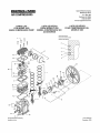
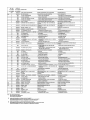
PARTS LIST
FOR MODEL SS5
BARE COMPRESSOR
PUMP
LISTA DE PIEZAS
PARA MODELO
SS5
BOMBA COMPRESORA
SIN
ACCESORIOS
POUR
LISTE DE PII_CES
COMPRESSEUR
MODELE SS5
NU,
Piston R}ng S_quenc_
Se_encla
de ani_lo_;de ptst6n
S_quence des segments
47
/
45
4
27
32
35
--
/
25-30
31 _|
35
8
9
42
19
18
2O
44
6-3
@ Ingersoll-Rand Company
Form SCD-876
Printed in U S A
December 1999
X
_L3
REF NO
PART NO
N_ DE REF.
N_ DE PIEZA
N= DE REP.
N" DE PIECE
REF,
QTY
DESCRIPTION
DESCRIPCt0N
DESCRIPTION
97334148
PUMP, BARE COMPRESSOR
BDMBA COMPRESORA
SET, PISTON
CON JUNTO DE ANILLOS
CANT.
QTY.
RING
SIN ACCESORIOS
COMPRESSEUR
1
20102703
2
NSS
e RING, COMPRESSION
• ANILLO DE COMPRES{0N
•
SEGMENT
DE COMPRESSION
3
NSS
• RING, SCRAPER
e ANILLO RASCADOR
I
SEGMENT
RACLEUR A _PAULEMENT
1
4
NSS
• RIND, OiL CONTROL SPACER
• ANILLO ESPACIADOR
•
SEGMENT
D'ESPACEMENT
2
•
SEGMENT
RACLEUR A FENTES
1
• RIND, OIL CONTROL
DE PISTON
NU
JEU DE SEGMENTS
REGULADOR DE ACEfTE
• ANILLO REGULADOR
1
5
NEE
6
95033593
PLUG. OIL DRAIN
TAPON ROSCADO
7
96705874
CAPSCREW
M8 X 65 (HE.AS BOLT)
TORNILLO DE CA_ET..A MB × 55 {PERNO DE
CULATA)
VIE D'ASSEMBLAGE
CULAESE)
M8 X 55 (BOULON
DE
E
8
98702253
CAPSCREW
M9 X 25 (CYLINDER
TORNtLLO DE CABEZA, M_. X 20 {PERNO DE
CILINDRO)
VIE D'ASSEMBLAGE
CYUNDRE}
Me X 20 (BOULON
DE
E
ARANDELA
RONDELLE
BOLT}
SPRING -- M5
DE ACEWE
2
DE PURGA DEL ACEITE
BOUDHON
9
$5725310
WASHER,
97333173
ASSEMBLY,
11
95705876
I2
20102711
13
NEE
• CRANKSHAFT
• CIGOEI_AL
• VILEBREQUIN
1
14
NES
I SEARING,
MA_N
• COJ}NETE PRINCIPAL
I
PALTER PRiNC{PAL
1
"IS
NSS
• BEARING,
BALL
l0 COJINETE DE BOLAS
t
PALIBR A BILLES
1
18
54423504
• WASHER
• ARANDELA,
•
RONDELLE M8
17
95730437
= CAPSCREW
THREAD
17A
95245494
10
97334254
II CAPSCREW,
ASSEMBLY,
ROD
MB X 35
LEFT HAND
t KEY, WOODRUFF
ASSEMBLY
•
OIL FILL PLUG
CON JUNTO DE C{GOE_AL,
ENSEMBLE
M8
• CHAVE[A
t
1
M8 X 14 FILBT_E. A,
1
CLAVETTE WOODRUFF
PARA RELLENOENSEMBLE
D'PIUtLE
DE BOUCHON
DE REMPUSSAGE
NSS
20
97334289
21
97333389
22
NSS
i!
PISTON
Ii PISTON
23
NSS
•
PiN. PISTON
• pAEADOR
24
NSS
•
RING, LOCK
II ANILLO DE FIJAC{0N
25
97335061
26
NEE
e PLATE, VALVE
la PLATILLO DE VALVULA
_l PLAGUE DE CLAPET
t
27
NES
• VALVE, DISCHARGE
• VALVULA
DE DESCARGA
o CLAPET DE REFOULEMENT
2
28
NSS
•
VALVE, INLET
• VALVULA
DE ADMISION
•
CLAPET D'ASPIRATION
2
29
NSS
t
STOP, DISCHARGE
I DETENEDOR
I
BUTte
2
30
NEE
•
RETAINER,
• RETCH, ADM_SiON
31
NEE
t
SCREW, HEX HEAD -- M3 X 15
32
NSS
It, NUT. I"IEX -- M3 WILOC!_.WASHER
ASSEMBLY,
ASSEMBLY.
PISTON & PiN
DE
It BOUCHON
• JOINT TORIQUE DE BOUCRON
REMPLISSAGE D'NUILE
CON JUNTO DE PISTON Y PASADOR
VALVE
ENSEMBLE
t
DE PISTON
CON JUNTO DE VALVULA
iNLET
DE
DE PISTON ET AXE
2
PISTON
t
• AXE DE PISTON
t
t
2
CIRCUP
t
DE REFOULEMENT
= VOLET DE RETENUE
• TORNtLLO DE CABEZA HEXAGONAL-• TUERCA HEXAGONAL
BLOQUEO
D'ASPIRATJON
2
M3 × 16 o VIE _ TI_:TE HEX. M3 X 16
-- M3 C/ARANDELA
•
_GROU HEX. M3 AVEC RONDELLE
SLOCAGE
BEL33NREEL
34
97330500
CAPSCREW
BOLTS)
35
97333488
CYLINDER
35
20102729
ASSEMBLY,
37
97335/324
39
NSS
39
97333843
40
97334 t71
FRAME, COMPRESSOR
BATIENTE,
_O
41
54429600
GASKET
EMPAQUErADURA,
PLAT$LLO DE VALVULA
JOINT DE PLAQUE DE CLAPET
1
X
42
07333546
GASKET, CYLINBER
EMPAQU_TADURA,
CJLiNDRO
JOINT DB CYLINDRE
1
[3
43
54410867
GASKET, HFJ_,D
EMPAQUErADURA
DE CULATA
JOINT DE CULASSE
1
44
97334270
GLASS, SIGHT
VISOR DE NIVEL
V_EEUR
1
45
54410683
HEAD
CULATA
CULASSE
49
70243936
ASSEMBLY.
CON JUNTO DE PURGA
ENEEMRLE
47
54408640
FILTER, INLET
FtLTRO DE ENTRADA
FILTRE D'ABPIRATIOF!
48
32170979
SEAL, SHAFT
SERVICE
VOLANT D'ENTRAi'NEMENT
1
TORN_LLO DE CABE7Jk ME X t4 (PERNOS DE
TAPA EXTREMA)
VIE D'AEEEMBLAGE
CARTER)
4
CILINDRO
CYLINDRE
CONJDNTO DE TAPA EXTREMA-ii OBTURADOR
•
• EMPAQUETADURA.
•
VENT
ELEMENT, FILTER
SERV{C{O
PARA EJES
• TAPA
VALVE PLATE
2
RUEDA DE POLEA
t COVER, END
GASKET. END COVER
D'ASPIRATtON
4
NSS
END COVER--
o BUTte
4
DE
97335756
M9 X 14 (END COVER
DE ADMISfON
DB
1
t
CLAPET
DE DESCARGA
i DETENEDOR
O'HUtLE
33
•
STOP, INLET
DE REMPLISSAGE
32A
NES
•
• JUNTA TOR{CA TAPON ROSCADO
RELLENO DE LUBRICANTS
PARA
1
19
I O-RING, OIL FILL PLUG
PARA RELLENO
2
I
I VIE D'ASSEMBLAGE
GAUCHE
DE MEDIA LUNA
MS X 25
DE V_LEBREQUIN
• TORNILLO DE CABF_?-A.M8 X 14--ROBCA
IZQUIERDA
i TAPON ROSCADO
LUBRICANTE
E
2
• VIE D'ABSEMBLAGE
SERVICIO
CON JUNTO DE TAPON ROSCADG
DE LUERICANTE
PLUG, OIL FILL
MB
BIELLE
Q TORNILLO DE CABE.ZA MS X 25
CF_%NKEHAFT -- SERVICE
MB X 29--
CON JUNTO DE B_ELA
A RESSORT
1
_i}
CONNECTING
DE MUELLE
DE VIDANGE D'HUILE
EXTREMA
TAPA DE F-..XTREMA
COMPRESOR
• ELEMENTO
NOT SOLDSEPARATELY
NO SE VENDE POR SEPARADO
NON VENDU S_PAREMENT
[3
AVAILABLE INDIVIDUALLY OR IN VALVE KiT 20100277
DISPONIBLE INDIVIDUALMENTE
O EN CON._UNTO DE V._LVULA 20100277
VENDU SEPARI_MENT OU DANE L'ENSEMBLE DE CLAPETS 20100277
X
AVAILABLE INDIVIDUALLY OR IN PISTON RING KIT 20100285
DISPONISLE INDIVlDUALMENTE
O EN CONIUNTO DE ANILLOB DE PISTON 20100285
VENDU SEPAR_MENT OU DANE L'ENSEMBLE DE SEGMENTS 20100285
DEL FILTRO
MB X t4 (BOULON DE
1
ENSEMBLE
DE CARTER
t
•
JOINT D'ARBRE
1
•
CARTER
1
•
JOINT DE CARTER
1
CHASSIS
DE COMPRESSEUR
1
1
D'EVENT
_11_L_MENT
FtLTRANT
1
1
1
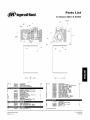
Parts
ingersoliRand
for Models
SS5L5
- 9C
List
& SS5N5
9D
5,6
3
•
8
261023.2.5
-
11-
',
-i
7
..4
--4
22.24
-14-•,
" " .......
<_-17,
• "-9,9A
20-"
,_
.
" 15
21
22
]
iTq--_,-',
F4"-,_
i
13
REF
2
3
NO
PART NO
84G03724
95750394
9733.148
4
5
8
_188518
56280159
7
8
9
9A
9S
9C
90
54416730
5441574_
97173595
9591S078
32496893
32241200
32175564
NI
54451 _0S
DESCRIPTION
CAPSCREW
WASHER, SPRING LOCK
PUMP. BARE COMPRESSOR
OTY
4
4
I
ASSEMBLY,
COMPLETE BELTGUARD
BRACE, BELTGUARD
SCREW, HEX _ SERRATED FLANGE -MS-1.0 X 12MM
BELTGUARD.
FRONT
BELTGUARD.
BACK
CAPSCREW,
SELF TAP -- I14-20 X 1/2
WASHER, FLAT 1/4 ZINC
CL JP, PVC COATED
FASTENER.
U l_PE
CAPSCREW
SERRATED _VASHBR HEAD - 114X3/4
GUARD. COMPRESSOR
END
1
1
I
1
1
4
4
4
I
1
1
p,, u:.0i_;q =!, j !.,[=t.-=_=(.],J
10
11
1_
95031795
87339303
220_0112
_W._I I ;] :] =[o] _ Lvj =_;il
12
97339311
@ [ngetsotI-R_nd
Printed
in U S A
C[_mpany
ELBOW, TUBE 518 X 112
ASSY
DISCHARGE
TUB_ -- SSBL5
ASSY DISCHARGE
TUBE -- SBBN5
#..101[1_
ASSY
;_l]l
REF
t3
14
15
15
16
16
17
17
18
18
19
20
21
22
22
Nt
NO
PART NO
32027120
3210555_
56291412
22109791
85582229
97333165
56269608
32499816
54372834
54627104
97004030
58289624
97171664
54442041
97010094
95.117507
D._SCR LPTION
VALVE. MANUAL DRAIN
VALVE BALL -- 1t2 FtF (SERVICE VALVE)
TANK A R RECE VER-- $8515
TANK, AIR RECEIVER-$85N5
VALVE¸ CHECK -- SS5L5
VALVE, CHECK -- BS5N5
GAUGE¸ PRESSURE -- B$515
GAUGE, PRESSURE -- SSBN5
SWITCH, PRESSURE -- SEBL5
SWITCH, PRESSURE -- SSBN5
CONNECTOR,
CABLE
PITTING_ MANIFOLD
VALVE, BAFETYIRELfEF
VALVE. SAFETWREL_EF
-- SSBL5
VALVE SAFETWRELIEF-SS5N5
N P_LE, ½ X 1-t1_-SSBN5
QTY
1
1
1
1
I
1
I
!
CAPSCREW
SERRATED
WASHER READ
SET. SHEAVE
NUT, WHIZ-LOCK
-- 5/16-18
MOTOR
BELT V--ASS
4
1
I
1
I
1
I
il_[o)_o];|_;|o]ll"
22
32175558
1
1
1
23
24
25
26
32117995
39128555
54421193
95099453
1
Ni = NOT ILLUSTRATED
1
4
1
1
|'
VENT TUBE -- 114
Fo_m SCD-878A
Match
2002
NOTES
START-UP KIT
Each slart_Up kit contI31n._enough Ingersoll-Rand
ISlet etem_nts tD starbup and mglnfaln your _,8
PART NO
20100251
DESCRIPTION
KIT. START*UP
INGERSOLL-RAND
LUBRICANT
PART NO,
3231867,5
32318683
AIR
SYNTHETIC
COMPRESSOR
DESCRIPTION
LUBRICANT, 1 QUART BOTTLE
LUBRICAN'E CASE OF 1 QUART BOTTLES
FILTER
PART NO,
32170979
synthetic compressor _ubricant _nd _Ir
fo_"lh_ first y_at
ELEMENT
DESCRIPTION
ELEMENT_ AIR FILTER
STEP SAVER KITS
Stop S_ve_ K_I_ provide
pit_lon timj t_placemt_n!
PART NO.
26109277
_;t of lhe parta _quiroct
or v_tVe _'opfscomgnt
DESCRIPTION
Kil_ VALVE/GASKET
1o gaff otto common repair task_ _uch as
CONTENTS
V_tve wQoring patt_ and h_ad
ga_,kets lhat _._odast_yed
in
__placing vaiv_ part_
201DO285
KIT RINGIGASKET
Compi_l_
c_anksh_f_
d_sttoyed
Io t_pl_e
CRANKCASE
set of pl,-_tontings,
_eal_ and _nskets th_t _r_
in bfe_k_n 9 lhe unit down
th_ tings¸
HEATER KIT
Crankcase heBI_rs a_ recommended
when amblen_ temperatures
are constsfentl_ below
32=F (O'C} An e_sy-to-instaI_ external crankcase heale_" k_t_s iniendad for _ftermarket
PART NO.
673303_5
DESCRIPTION
K_T, CRANKCASE
MULTI-PURPOSE
Thes{z ah hose assemblies
working pro_,_Ure
HEATER
AIR HOSES
a_e h_avy d_ly
fight w_ighl hos_s deslgn_d f_r 300 PStG
PART NO,
DESCRtPT'O"
323237_8
32323776
HOSB. AIR -- 3/g" X 50 1N" MALE NPT
HOSE. AIR -- 3/8" X 100 (1/4" MALE NP )
2323 6
fl"'MA
T
Y-STRAINERS
Yostta_nors are des_gn,_d ls ptevorti foreign
PART NO
32323528
32323635
DESCRfPTION
Y-STRAINER,
Y-STRAINER,
1/4"
112"
part_olas from moving downstream