1
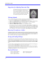
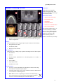
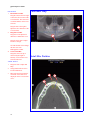
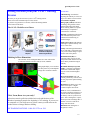
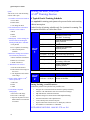
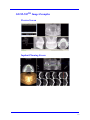
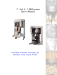
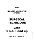
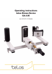
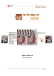
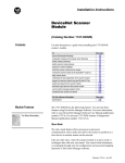
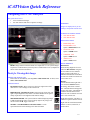
iCATVision Quick Reference
Navigating the i-CAT® Interface
This guide shows how to:
•
•
View reconstructed images
Use main features and tools to optimize an image.
REMINDER
Images are displayed as if you are
looking at the patient from the front.
TO DISPLAY PATIENT IMAGE
1. Click Patient Name.
1
2.
Click Patient Scans
DISPLAYED VIEWS
4
2
3
5
6
7
3.
Patient Study Info
4.
PANORAMIC View
Opens to IMPLANT Screen
5.
SAGITTAL View
Opens to CEPH Screen
6.
CORONAL View
Opens to MPR Screen
7.
AXIAL View
Opens to TMJ Screen
MEASUREMENTS
NOTE: Images shown in this document were acquired on a 17-19 system. Images
acquired on a GXCB-500™ system may have a smaller field of view (examples are
shown at the end of this document).
Tools for Viewing this Image
HIDING THE PATIENT LIST
Patient List can be hidden by selecting Tools > Hide Patient List. To show, select
Tools > Show Patient List.
CURSOR TOOLS
ROTATION TOOL - Hover cursor over the lower right corner of the
desired view. Cursor changes to the rotation tool.
BRIGHTNESS / CONTRAST TOOL - Drag cursor up, down, left, and
right to adjust brightness and contrast. Use Reset Window/Level options
on Pop Up menu to reset brightness and contrast settings.
MIP/RADIOGRAPH - The system software enables displaying images
as MIP or Radiograph. Move cursor to the top right of any image. The
cursor becomes an M, toggle a selection.
MAXILLA and MANDIBLE CONTOUR LINES - can be
repositioned with a click and drag to the desired location.
HU Statistics
(Bone Density) Right click a view
and select HU Statistics. Drag and
click to define an area. Statistics
appear in upper right corner. A
maximum of 4 HU stats can be taken
at a time in a normal view and 2 in a
cross section view.
Distance
(Linear Measurement) right click a
view and select Distance. Point,
click, drag, and release to draw a
line. A measurement in mm appears
in upper left corner. A maximum of
9 distance measurements can be
taken at a time in a normal view and
4 in a cross section view.
Right click and select “HU Stats” or
“Distance” again to turn the tool off
Right click the actual measurement
statistic to remove, inactivate, or
activate them.
D-1
Quick Reference Guide
Suggestions for Adjusting Panoramic Map
Start adjusting the Panoramic map from the Preview
Screen. It is recommended to center the anterior
point at midline and then move the next two points
up closer to the anterior point on each side. Place
them a few teeth away from anterior center. Then
move the next two points closer to the molars.
Filtering Defaults
There are already filters applied to all images. The filters are defaulted as seen below.
1. Preview Screen: Hardon Panoramic and Sharpen Mild for all others.
2. Implant Screen: Sharpen Mild on Axial Slice and Cross Sections - Hard on Panoramic Map.
3. TMJ Screen: Hard for top row images and Sharpen Mild for Condyle Ceph Images.
4. MPR Screen: Sharpen Mild all images.
5. Ceph Screen: Sharp for Upper Left Right Lateral and Hard for all others.
These defaults can always be changed by clicking Tools > Filter Settings > Set Filters. They
can also be changed “on the fly” by right clicking an individual image, selecting Filter Setting
> Set Filter and clicking the desired option (Smooth, Normal, Hard, Sharp, Very Sharp). They
can be changed back to the default by clicking Tools > Filter Settings > Reset to Default.
Removing Circumference Artifact
Circumference Artifact are seen visually in the Preview Screens as horizontal lines in the Coronal
and Sagittal images and a white partial circle around the axial image. This can be removed from the
dataset by right clicking the screen and selecting Remove Data Outside of Center Scanfield. The
data re-calculates and the image is displayed without that artifact.
Saving and Loading Workups
Created plans can be saved for retrieval. When a plan is changed and an attempt to exit or switch
patients is made, iCATVision prompts to save the workup. To save the workup, click Yes. A window
is displayed to Create New Workup. Click this button and enter a new title for the workup or choose
an existing workup name (if one) from the list to overwrite. Once the workup is named, click OK to
save.
Or, before exiting or switching patients, from the Preview Screen, right click to access the pop up
menu and select Save this Workup. Then proceed as instructed above.
To load a workup, click a Patient Name, and Patient Image, and then a workup. To select another
workup (if there are multiple workups), right click the screen to access the pop up menu and select
Load Different Workup. Then select the workup from the list.
Keyboard Shortcuts
Alt + S - Opens Setup dialog
Alt + F - Opens File menu
Alt + T - Opens Tools menu
D-2
Alt + R - Opens Screen menu
Alt + F - Opens Help menu
Quick Reference Guide
Implant Planning Screen
1
REMINDER
2
Implant Screen is acquired by
double clicking Panoramic View
from Preview window or selecting it
from the Screen menu.
DISPLAYED VIEWS
5
3
6
4
1.
AXIAL SLICE POSITION
2.
PANORAMIC MAP
3.
3D MODEL
4.
CROSS SECTIONS
5.
Center Slice is outlined in Blue.
6.
Slice Location Number
Slice Location numbers start at “0”
for center of anatomy or midline.
(The “0” slice is outlined in Red).
All slices to the patient’s right are
negative #’s. All slices to the
patient’s left are positive #’s.
Midline is determined by axial map.
•
Double click an individual Cross Section to zoom in. Double click again to
reduce to original size.
LABELS:
The following labels on the images help clarify the orientation of the anatomy:
•
R: Right Side (Axial, Pan)
•
P: Posterior (Axial)
•
B: Buccal (Cross Sections)
POP UP MENUS
Right click views to display a Pop Up menu containing a subset of these options:
•
HU Statistics
•
Distance
•
Display Formats: The default is 5 x 2. The other options are 7 x 3 and 3 x 1.
•
Set Filters
•
Save as JPEG
•
Open Output Folder
•
Estimate Nerve Canal
CURSOR TOOLS
•
All views, except the 3D Model, have Brightness/Contrast, Rotate, Drag,
Zoom and Pan. 3D Model only has Rotate.
•
The mouse scroll wheel is active on the Axial Slice Position, 3D Model and
Cross Sections to scroll through slices.
•
Back Tool: to exit out of a planning screen back to the Main Display,
move cursor to the very top left corner of screen until X is displayed
and click. Or click the Screen option on the Main Menu bar.
D-3
Quick Reference Guide
PAN TOOLS
1.
Panoramic Map
Horizontal Tool Bar
Drag this center tool left to right
to move the slice location of the
Cross Sections. The center slice
is outlined in Blue on the Cross
Sections.
Drag the tool to the right to
adjust the slice thickness of the
Cross Sections.
2.
3
2
Diagonal Tool Bar
Drag this tool to adjust slice
thickness of Panoramic View.
1
Drag the center tool to adjust
Pan Focal Trough.
Click the bottom tool to change
the Pan view from
Radiographic to MIP.
3.
Vertical Tool Bar
Drag this center tool up or
down to adjust height of
anatomy viewed in the Cross
Sections and Axial.
Axial Slice Position
AXIAL TOOLS
1.
Drag blue dots to adjust Pan
Map.
2.
Orange hash marks are Slice
Location Indicators.
3.
Blue hash mark represents the
centerline of the axial slices
displayed on the Cross Section
views.
2
1
D-4
3
Quick Reference Guide
Ceph Screen
REMINDER
Ceph Screen is acquired by double
clicking Sagittal View from Preview
window or selecting it from the
Screen menu.
DISPLAYED VIEWS
The Ceph Screen displays the
Lateral Cephs in Radiographic and
MIP mode as well as a Coronal
View and a Mid Sagittal Slice
(15mm thick).
CURSOR TOOLS
All views have Brightness/Contrast,
Zoom and Pan.
1
1.
Right click blank screen and select Tag Airways. This generates a 3D view of the
airways for the patient in the blank view. In addition, the tagged airway data is
displayed in the view at the bottom center of the Ceph screen.
•
•
•
Set Filters
Save as JPEG
Open Output Folder
REMINDER
MPR Screen is acquired by double
clicking Coronal View from
Preview window or selecting it from
the Screen menu.
MPR Screen
1
POP UP MENUS
Right click to display the Pop Up
menu to select:
DISPLAYED VIEWS
The MPR Screen allows scrolling
through the Axial, Sagittal, and
Coronal Slices. Mouse scroll wheel
is active to scroll through slices.
2
CURSOR TOOLS
All views have Brightness/Contrast,
Zoom and Pan.
3
1.
Drag center tools from any view to move slice location. The views are colored coded
to correlate which view will adjust.
2.
Drag tool to the right for horizontal and bottom for vertical bars to adjust slice
thickness of the corresponding color coded view.
3.
Right click any of the 3 views and select Irregular, Line, or Explore for additional
cut planes to be displayed in the blank area.
POP UP MENUS
Right click to display the Pop Up
menu to select:
•
•
•
•
•
•
•
•
•
•
Irregular
Line
HU Statistics
Distance
Explore
Explore Speed
Set Filters
Save as JPEG
Open Output Folder
Reset Volume Rotation
D-5
Quick Reference Guide
REMINDER
TMJ Planning Screen is acquired by
double clicking Axial View from
Preview window or selecting it from
the Screen menu.
TMJ Planning Screen
1
DISPLAYED VIEWS
TMJ Screen enables condyle
mapping and creating
corresponding coronal slice views.
2
3
CURSOR TOOLS
All views have Brightness/Contrast,
Zoom and Pan.
POP UP MENUS
Right click to display the Pop Up
menu to select:
• Set Filters
• Save as JPEG
• Open Output Folder
HINT
It may be necessary to first drag the
Axial (SMV) view down in the
window to see the condyles. Move
the cursor to the lower left of the
SMV (axial) view until displayed is
the “P” for pan tool to drag the
image downward.
1.
Drag center tool to scroll up and down Sagittal view to locate condyles in the Axial
view to display condyles properly for mapping.
2.
Create Lateral Slices:
Drag center blue circles to move condyle map (do this for each condyle)
Drag yellow and blue end circles to adjust the angle of each condylar map.
Green markings indicate anterior to condyle.
Red marking indicate posterior of condyle.
Create Coronal Slices: Click red circle on either end map to create Coronal views.
3.
Horizontal Tool Bar: Drag center tool left to right to move slice location of Cross
Section views. Drag tool right to change slice thickness of Cross Section views
Create Export CDs
NOTE:
Make sure to Save Workups before
attempting to burn to a CD,
1.
From the top Main menu,
select Tools > Create Export
CD.
2.
If you have multiple CD
drives, select the hardware
from the drop down list. If
using a CD-RW and need to
erase data, choose Erase CDRW.
3.
Click the patient for burning to
CD. If selecting multiple
patients, hold down the CTRL
key and click on additional patients. All highlighted patients are copied to the CD.
4.
Click Create CD in CD burner window. A message is displayed when the burn
is complete and the CD ejects.
Install Case Studies
from CDs
The iCATVision program will autorun when the CD is inserted into the
computer drive. The User can
choose to install iCATVision and the
case(s) Permanently or Temporarily.
Once installed, the iCATVision
program opens and the new case is
highlighted in the patient list and
ready to be loaded. Just click the
patient name.
D-6
Quick Reference Guide
Getting the most from your i-CAT® Training
Session
We want you to get the most out of your i-CAT® training session.
Please review this information prior to this session.
If you have any questions or concerns, call the ISI training number
at the bottom of this sheet.
The i-CAT® Workflow at a Glance
GLOSSARY
3-D Rendering: A method of
depicting the anatomy as a true 3-D
object as would be seen in real life.
Cone Beam Computed
Tomography (CBCT): The latest
technology that generates a three
dimensional image of the skull
while reducing radiation exposure
substantially as compared to
conventional CT scanners.
DICOM: A standardized file format
and communication protocol for
transmission and archiving of
medical images.
Field of View (FOV): The diameter
and height of patient anatomy seen
in an i-CAT® scan.
1
3
2
Acquire
Scan
View Images
and Prepare
Reports
Output in a Variety of
Formats and Export to
Third-Party Software
Thinking in Three Dimensions
The Coronal, Axial, and Sagittal Planes are color coded in the
iCATVision software interface as Red, Green, and Blue.
AXIAL
PLANE
SAGITTAL
PLANE
This graphic helps you to visualize
the three planes as you manipulate
images in iCATVision software.
CORONAL
PLANE
Gantry: The rotating mechanism on
the i-CAT® that is composed of the
x-ray source and the image receptor
at either side of the patient.
Hounsfield Unit (HU): A
numerical value used in CT scan
interpretation that characterizes the
tissue density within the imaged
anatomy.
Maximum Intensity Projection
(MIP): A computer visualization
method for 3-D data that depicts
only the voxels with the highest
density.
Reconstructed Data: The 3-D
volume generated by software from
the raw projections captured during
the scan.
Resolution: The ability to see fine
details in an object. A higher
resolution implies finer detail.
Click, Zoom, Burn: Are you ready?
All trainees must be proficient with the basic tools and functions of the
Windows Operating System before beginning i-CAT® training. If you are new
to computers or if your skills are rusty, please contact your ISI trainer at the
number below to arrange Windows training.
ISI TRAINING HOTLINE: 1-800-205-3570 ext. 284
Voxel: A voxel (a combination of
the words volumetric and pixel) is a
volume element which represents
the density value of a point in 3-D
space. This is analogous to a pixel,
which represents 2-D image data. A
smaller voxel size results in an
image with finer detail.
Window/Level: Analogous to
Brightness/Contrast.
D-7
Quick Reference Guide
Just for fun, we’ll start the training
session with a quiz!
Getting the most from your
i-CAT® Training Session
1. A smaller voxel size will result in:
A Typical Onsite Training Schedule
QUIZ
A: Less detail
B: More detail
C: No change in detail
2. The Axial Plane in iCATVision
software is color coded as:
It is required for training participants to be present for the entire training
without interruption.
On the first day of training, schedule only 2 to 4 patients for scanning. The
first patient should be no earlier than 10 am.
A: Red
TIME
B: Blue
ACTIVITY
8:30 am – 8:45 am
Introduction to the i-CAT®
and CBCT Technology
8:45 am – 9:15 am
Physical Mechanisms and
Safety Features
A: No patients
9:15 am – 10:00 am
i-CAT® software basics
B: 2 to 4 patients for scanning
10:00 am – 10:45 am
Positioning a patient and
acquiring a scan
10:45 am – 11:15 am
Acquire second patient scan
11:15 am – 12:15 pm
Post-scan image processing
12:15 pm – 1:00 pm
Lunch
1:00 pm – 3:00 pm
Post-scan image
processing, continued
3:00 pm – 5:00 pm
Output of reports and
exporting studies
5:00 pm – 5:30 pm
3DVR Software (3D Renderings)
C: Green
3. During Day 1 of the training, the
staff and doctors attending the
training should plan to schedule:
C: Their normal patient
schedule
4. Before the training session, future
users should be proficient in:
DAY
1
A: Basic functions of Windows
B: Basic use of a mouse
C: Both of the above
5. “Window/Level” refers to:
A: The tilt of the monitor
B: The location of the image on
the screen
C: The brightness and contrast
of the image
6. Images taken with the i-CAT®
can be exported as:
DAY
2
TIME
ACTIVITY
8:00 am – 12:00 pm
Onsite Coaching: One Scan per Hour.
Review as Needed.
A: DICOM
B: FOV
During Training, you will Learn to:
C: MIP
Position the patient to acquire the best possible scan
7. Cone Beam Computed
Tomography:
•
Navigate the iCATVision Software Interface Quickly and Easily
•
Visualize 3-D Anatomical Forms from 2-D Onscreen Images
A: Provides a 2-D image
•
Map and Measure Anatomical Features
B: Provides a 3-D image
•
Optimize Images for TMJ Treatment and Implant Planning
C: Exposes the patient to more
radiation than a conventional
CT scanner
•
Generate Panoramics and Cephalometrics
•
Create, Modify, Print, and Save Reports
•
Export in DICOM 3 Format for use in Third-party Software
•
Save Studies to a Hard Drive or CD-ROM
ISI TRAINING HOTLINE: 1-800-205-3570 ext. 284
D-8
GXCB-500TM Image Examples
Preview Screen
Implant Planning Screen
D-9
Quick Reference Guide
Ceph Screen
MPR Screen
TMJ Planning Screen
D-10