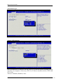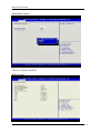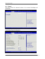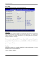
1
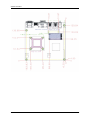
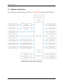
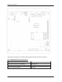
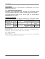
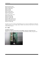
WADE-8020
User's Manual
Version 1.4
Copyright © Portwell, Inc., 2012. All rights reserved.
All other brand names are registered trademarks of their respective owners.
Preface
Table of Contents
How to Use This Manual
Chapter 1......................................................................................................................................1-1
System Overview ........................................................................................................................1-1
1.1 Introduction ....................................................................................................... 1-1
1.2 Check List........................................................................................................... 1-1
1.3 Product Specification........................................................................................ 1-2
1.3.1 Mechanical Drawing................................................................................ 1-4
1.4 System Architecture.......................................................................................... 1-6
Chapter 2......................................................................................................................................2-1
Hardware Configuration .............................................................................................................2-1
2.1 Jumper Setting ................................................................................................... 2-1
2.2 Connector Allocation........................................................................................ 2-3
Chapter 3......................................................................................................................................3-1
System Installation .....................................................................................................................3-1
3.1 Intel® i7/i5/P4500 PGA .................................................................................. 3-1
3.2 Main Memory .................................................................................................... 3-1
3.3 Installing the Mini-ITX Board Computer ...................................................... 3-2
3.3.1 Chipset Component Driver .................................................................... 3-2
3.3.2 Intel® Integrated HD Graphics Controller .......................................... 3-2
3.3.3 Intel Gigabit Ethernet Controller ........................................................... 3-3
3.3.4 Audio Controller ...................................................................................... 3-3
3.3.5 Clear CMOS Operation ........................................................................... 3-4
3.4 GPIO.................................................................................................................... 3-4
3.4.1 Pin assignment ......................................................................................... 3-4
3.4.2 WADE-8020 GPIO Programming Guide.............................................. 3-5
3.4.3 Example ..................................................................................................... 3-6
Chapter 4......................................................................................................................................4-1
BIOS Setup Information..............................................................................................................4-1
4.1 Entering Setup -- Launch System Setup ........................................................ 4-1
4.2 Main .................................................................................................................... 4-2
4.3 Advanced ........................................................................................................... 4-3
4.4 Chipset.............................................................................................................. 4-13
4.5 Boot ................................................................................................................... 4-16
4.6 Security ............................................................................................................. 4-19
4.7 Save & Exit ....................................................................................................... 4-21
Chapter 5......................................................................................................................................5-1
Preface
Troubleshooting..........................................................................................................................5-1
5.1 Hardware Quick Installation........................................................................... 5-1
5.2 BIOS Setting ....................................................................................................... 5-3
5.3 FAQ ..................................................................................................................... 5-4
Preface
How to Use This Manual
The manual describes how to configure your WADE-8020 system board to meet
various operating requirements. It is divided into five chapters, with each chapter
addressing a basic concept and operation of Single Host Board.
Chapter 1: System Overview. Presents what you have in the box and give you an
overview of the product specifications and basic system architecture for this series
model of single host board.
Chapter 2: Hardware Configuration. Show the definitions and locations of Jumpers
and Connectors that you can easily configure your system.
Chapter 3: System Installation. Describes how to properly mount the CPU, main
memory and Compact Flash to get a safe installation and provides a programming
guide of Watch Dog Timer function.
Chapter 4: BIOS Setup Information. Specifies the meaning of each setup
parameters, how to get advanced BIOS performance and update new BIOS. In
addition, POST checkpoint list will give users some guidelines of trouble-shooting.
Chapter 5: Troubleshooting. Provide various of useful tips to quickly get
WADE-8020 running with success. As basic hardware installation has been
addressed in Chapter 3, this chapter will basically focus on system integration issues,
in terms of backplane setup, BIOS setting, and OS diagnostics.
The content of this manual is subject to change without prior notice. These changes
will be incorporated in new editions of the document. The vendor may make
supplement or change in the products described in this document at any time.
System Overview
Chapter 1
System Overview
1.1 Introduction
Powell Inc., a world-leading innovator in the Industrial PC (IPC) market and a
member of the Intel® Communications Alliance, has launched its new WADE-8020 in
response to market demand for a simplified embedded system board (ESB) that
combines a smaller footprint, lower power consumption, robust computing power
and with longevity support.
Based on latest mobile Intel® QM57 Express chipset, WADE-8020 takes advantage of
Intel® Core™ i5 / i7 processor which has high performance and excellent power
management features. WADE-8020 not only supports dual display by VGA / DVI /
HDMI / LVDS and the third display via PIC-Express expansion slot. In addition,
with its display-enriched interface, WADE-8020 can support various multimedia
devices.
Built with 32nm Intel® Core™ i5 / i7 processor and Mobile Intel® QM57 Express
chipset, WADE-8020 can provide the best solution for multiple applications such as
POS, DVR, Mobile Kiosk, Lottery, Gaming and Digital Signage.
1.2
Check List
The WADE-8020 package should cover the following basic items
One WADE-8020 Mini-ITX Main Board
One SATA Cable
One I/O Shield bracket
One Installation Resources CD-Title
If any of these items is damaged or missing, please contact your vendor and keep all
packing materials for future replacement and maintenance.
WADE-8020 User’s Manual
1-1
System Overview
1.3 Product Specification
z Main Processor
- Intel®Core™ i5 / i7 processor
- CPU clock bus: 1333/1066/800 MHz
z Chipset
Intel® QM57 Express chipset
z System BIOS
AMI BIOS
z Main Memory
Two 204-pin DDR3 SODIMM socket support up to 8GB dual channel 800/1066
MHz memory
z Expansion Interface
- One PCI slot and One PCI-E x1 slot
- One Mini PCI-E slot
z SATA Interface
Six SATA ports
z Serial Port
Support three RS232 ports and one RS232/422/485 port
z USB Interface
Support eight USB (Universal Serial Bus) ports, four on rear I/O and four on
board header for internal devices
z Audio Interface
Connector for Mic-In, Line-In and Line-Out
z Watch Dog Timer
- Support WDT function through software programming for enable/disable and
interval setting
- General system reset
z On board VGA
Intel® Gen 6.0 integrated graphic engine
z On-board Ethernet LAN
Two Gigabit Ethernet (10/100/1000 Mbits/sec) LAN ports using Intel 82574L and
82577LM GbE Ethernet Controller
z High Drive GPIO
Onboard programmable 16-bit Digital I/Os (8x In/Out)
WADE-8020 User’s Manual
1-2
System Overview
z Cooling Fans
Support one 3-pin power connector for CPU cooler and one 3-pin power
connector for system fan
z System Monitoring Feature
Monitor system temperature and major power sources.
z Outline Dimension (L x W)
170mm(6.69’’) x 170mm(6.69’’)
z Power Requirements
Configuration
CPU Type
Intel® Core™ i5 CPU M520 @2.4GHz L3:3MB Bus Speed:133MHz
SBC BIOS
Portwell,Inc. WADE-8020 BIOS Rev.:R1.00.E0(09012010)
Memory
Transcend DDR3 1066 1GB (ELPIDA J1108BDBG-DJ-F)
VGA Card
Onboard Intel® QM57
VGA Driver
Intel® Graphics Media Accelerator HD Version 6.14.10.5789
LAN Card
Onboard Intel® 82574L Gigabit Network Connection
LAN Driver
Intel® 82574L Gigabit Network Connection Version 11.4.7.0
LAN Card
Onboard Intel® 82577LML Gigabit Network Connection
LAN Driver
Intel® 82577LML Gigabit Network Connection Version 11.5.10.0
Audio Card
Onboard Realtek ALC888 Audio
Audio Driver
Realtek High Definition Audio Version 5.10.0.6043
Chip Driver
Intel® Chipset Devices Software Version 9.1.1.1025
USB 2.0 Driver
Intel® 5 series/3400 Series Chipset Family USB Enhanced Host
Controller Version 9.1.1.1013
SATA HDD
Seagate ST3160815AS 160GB
CDROM
LITE-ON LH-20A1S DVD-ROM
Power Supply
FSP350-60GLC
Item
Power ON
Full Loading 10Min
Full Loading 30Min
CPU +12V
0.94
1.23
1.25
System +12V
0.30
0.33
0.33
System +5V
3.31
3.49
3.55
WADE-8020 User’s Manual
1-3
System Overview
z Operating Temperature
0 °C ~ 60 °C
z Storage temperature
-20 ~ 80 °C
z Relative Humidity
0% ~ 90%, non-condensing
1.3.1 Mechanical Drawing
WADE-8020 User’s Manual
1-4
System Overview
WADE-8020 User’s Manual
1-5
System Overview
1.4 System Architecture
All of details operating relations are shown in WADE-8020 System Block Diagram.
WADE-8020 System Block Diagram
WADE-8020 User’s Manual
1-6
Hardware Configuration
Chapter 2
Hardware Configuration
This chapter indicates jumpers’, headers’ and CONNECTORs’ locations. Users may
find useful information related to hardware settings in this chapter.
2.1 Jumper Setting
WADE-8020 User’s Manual
2-1
Hardware Configuration
The jumper settings are schematically depicted in this manual as follows:
JP5: COM2 RS232, 422, 485 Selection
JP5
5-6,9-11,10-12,15-17,16-18 Short
3-4,7-9,8-10,13-15,14-16,21-22 Short
1-2,7-9,8-10,19-20 Short
WADE-8020 User’s Manual
Function
RS-232 Ì
RS-422
RS-485
2-2
Hardware Configuration
JP13: VDDLVDS_IN Selection
JP13
1-3 Short
3-5 Short
3-4 Short
Function
VCC3 Ì
VCC
+12V
JP15: CMOS Clear Header
JP15
1-2 Open
1-2 Short
Function
Normal Operation Ì
Clear CMOS Contents
JP14 ME RTC Clear Header
JP14
1-2 Open
1-2 Short
Function
Normal Operation Ì
CLEAR ME RTC REGISTER
2.2 Connector Allocation
I/O peripheral devices are connected to the interface connectors.
Connector Function List
Connecto
Function
r
JP6
COM3 Pin Header
JP7
COM4 Pin Header
JP9
Backlight POWER CONNECTOR
JP10
Front Panel Pin Header
JP11
LVDS Backlight VDD SETTING
JP12
LPC Debug Pin header
J5
AUDIO CONNECTOR
J6
VGA+DVI CONNECTOR
J7
COM1+COM2 NNECTOR
J8
USBX2 + LAN CONNECTOR
J9
USBX2 + LAN CONNECTOR
J11
ATX 4P CONNECTOR
J12
PCI CONNECTOR
WADE-8020 User’s Manual
Remark
2-3
Hardware Configuration
J13
CPU FAN CONNECTOR
J14
16-bit GPIO Pin Header
J15
LVDS CONNECTOR
J16
PCI-E X1 SLOT
J17
USBx2 Pin Header
J18
DDR3 SODIMM SOCKET
J19
SATA CONNECTOR
J20
SATA CONNECTOR
J21
SATA CONNECTOR
J22
DDR3 SODIMM SOCKET
J23
USBx2 Pin Header
J25
SATA CONNECTOR
J26
SATA CONNECTOR
J27
SATA CONNECTOR
J29
SYSTEM FAN CONNECTOR
J30
ATX 20P CONNECTOR
J32
Mini-PCI-E CONNECTOR
Pin Assignments of Connectors
JP6: COM3 Pin Header
Pin No.
1
2
3
4
5
6
7
8
9
10
Signal Description
DCD#
DSR#
RXD#
RTS#
TXD#
CTS#
DTR#
RI#
GND
NC
WADE-8020 User’s Manual
2-4
Hardware Configuration
JP7: COM4 Pin Header
Pin No.
1
2
3
4
5
6
7
8
9
10
Signal Description
DCD#
DSR#
RXD#
RTS#
TXD#
CTS#
DTR#
RI#
GND
NC
JP8: SM Bus Pin Header
Pin No.
1
2
3
Signal Description
SMB_CLK
SMB_DATA
GND
JP9: Backlight POWER CONNECTOR
Pin No.
1
2
3
4
5
Signal Description
ENABLE
GND
+12V
GND
VCC
JP10: Front Panel Pin Header
PIN No.
1
3
5
7
9
11
13
Signal Description
VCC
HD_LED#
GND
RESET#
NC
GND
VCC
WADE-8020 User’s Manual
PIN No.
2
4
6
8
10
12
14
Signal Description
Power on LED
GND
PWRBTN
GND
NC
GND
KEY
2-5
Hardware Configuration
JP11: LVDS Backlight VDD SETTING
Pin No.
1-3, 2-4
1-3, 4-6
3-5,2-4
3-5,4-6
Signal Description
5V, Active High
12V, Active High
5V, Active Low
12V, Active Low
JP12: LPC Debug Pin header
PIN No.
6
7
8
9
10
Signal Description
LAD0
LAD1
LAD2
LAD3
KEY
PIN No.
1
2
3
4
5
Signal Description
VCC3
PLT_RST#
LFRAME#
CLOCK
GND
PIN No.
2
4
6
8
10
12
14
16
18
Signal Description
GPIO32
GPIO33
GPIO36
GPIO37
GPIO74
GPIO75
GPIO76
GPIO77
VCC
J13: CPU Fan connector
Pin No.
1
2
3
4
Signal Description
GND
+12V
SENSE
PWM_CONTROL
J14: 16-bit GPIO
PIN No.
1
3
5
7
9
11
13
15
17
Signal Description
GPIO11
GPIO12
GPIO30
GPIO31
GPIO70
GPIO71
GPIO72
GPIO73
GND
WADE-8020 User’s Manual
2-6
Hardware Configuration
J15: LVDS CONNECTOR
Pin No.
2
4
6
8
10
12
14
16
18
20
22
24
26
28
30
Signal Description
VDD
LVDSA_DATA#0
LVDSA_DATA#1
LVDSA_DATA#2
LVDSA_DATA#3
LVDSA_CLKN
LVDS_DDC_DATA
GND
LVDSB_DATA#0
LVDSB_DATA#1
LVDSB_DATA#2
LVDSB_DATA#3
LVDSB_CLKN
NC
GND
Pin No.
1
3
5
7
9
11
13
15
17
19
21
23
25
27
29
Signal Description
VDD
LVDSA_DATA0
LVDSA_DATA1
LVDSA_DATA2
LVDSA_DATA3
LVDSA_CLKP
LVDS_DDC_CLK
GND
LVDSB_DATA0
LVDSB_DATA1
LVDSB_DATA2
LVDSB_DATA3
LVDSB_CLKP
NC
GND
PIN No.
2
4
6
8
10
Signal Description
J29: SYS FAN CONNECTOR
Pin No.
1
2
3
Signal Description
GND
PWM_CONTROL
SENSE
J17 & J23: USBx2 Pin Header
PIN No.
1
3
5
7
9
Signal Description
VCC
DATA DATA +
GND
KEY
WADE-8020 User’s Manual
VCC
DATA DATA +
GND
GND
2-7
Hardware Configuration
J30 : ATX Power Connector
PIN No.
1
2
3
4
5
6
7
8
9
10
Signal Description
+3.3V
+3.3V
GND
+5V
GND
+5V
GND
PWR_OK
+5VSB
+12V1
WADE-8020 User’s Manual
PIN No.
11
12
13
14
15
16
17
18
19
20
Signal Description
+3.3V
-12V
GND
PS_ON#
GND
GND
GND
NC
+5V
+5V
2-8
System Installation
Chapter 3
System Installation
This chapter provides you with instructions to set up your system. The additional
information is enclosed to help you set up onboard PCI device and handle Watch
Dog Timer (WDT) and operation of GPIO in software programming.
3.1 Intel® i7/i5/P4500 PGA
WADE-8020 has equipped the most advanced Intel® Core™ i5/i7 series CPUs which
has built-in Intel® HD Graphics Controller providing a total solution of
multi-purpose operation. Furthermore, the leading-edge Intel® Core™ processor
delivers unmatched technology for intelligent performance on the most demanding
tasks, such as creating digital video and playing intense games. With building into
WADE-8020 Mini-ITX board computer, it can be applied in many different uses
depending on the configurations of system setup.
Support List
Intel® Core™ i7-820QM Processor
Intel® Core™ i7-620M Processor
Intel® Core™ i5-520M Processor
Intel® Celeron® Processor P4500
3.2 Main Memory
WADE-8020 provides 2 x 204-pin SO-DIMM sockets which supports dual channel
DDR3 800/1066 MHz SDRAM as main memory. The maximum memory size can be
up to 8GB capacity.
For system compatibility and stability, do not use memory module without brand.
Memory configuration can be either one double-sided DIMM in either one DIMM
socket or two single-sides SO-DIMM in both sockets.
Watch out the contact and lock integrity of memory module with socket, it will
impact on the system reliability. Follow normal procedures to install memory module
into memory socket. Before locking, make sure that all modules have been fully
inserted into the card slots.
Dual Channel DDR3 SO-DIMM
Dual Channel DDR3 memory technology doubles the bandwidth of memory bus.
Adequate or higher bandwidth of memory than processor would increase system
performance. To enable Dual Channel DDR3 memory technology, you have to install
dual identical memory modules in both memory sockets. Following tables show
bandwidth information of different processor and memory configurations.
WADE-8020 User’s Manual
3-1
System Installation
CPU FSB
1066MHz
800MHz
Bandwidth
8.5GB/s
6.4GB/s
Memory Frequency
1066MHz
800MHz
Dual Channel DDR Bandwidth
17GB/s
12.8GB/s
Note:
To insure the system stability, please do not change any of DRAM parameters in
BIOS setup to modify system the performance without acquiring technical
information
3.3 Installing the Mini-ITX Board Computer
To install your WADE-8020 into standard chassis or proprietary environment, please
perform the following:
Step 1 : Check all jumpers setting on proper position
Step 2 : Install and configure CPU and memory module on right position
Step 3 : Place WADE-8020 into the dedicated position in the system
Step 4 : Attach cables to existing peripheral devices and secure it
Note:
Please refer to section 3.3.1 to 3.3.4 to install INF/VGA/LAN/Audio drivers.
3.3.1 Chipset Component Driver
WADE-8020 uses state-of-art Intel® QM57 chipset. It’s a new chipset that some old
operating systems might not be able to recognize. To overcome this compatibility
issue, for Windows Operating Systems such as Windows XP/Vista/Win7, please
install its INF before any of other Drivers are installed. You can find this chipset
component driver very easily in installation CD of WADE-8020.
3.3.2 Intel® Integrated HD Graphics Controller
Unlike the other structure, WADE-8020 has integrated HD Graphics derived from
Intel® Core™ series CPU (i5/i7) technology. It is the most advanced design to gain
an outstanding graphic processing performance in a compact size. Support
DVMT/Fixed mode for integrated graphic memory size up to the maximum
DDR3-SDRAM capacity. WADE-8020 supports VGA, DVI-D, HDMI, and integrated
LVDS display output. This combination makes WADE-8020 an excellent piece of
multimedia workstation.
With no additional video adaptor, this onboard graphic controller will be the primary
system graphic processing handler. By adjusting the BIOS setting to disable on-board
VGA, an add-on PCI-Express graphic card can take over the system display.
WADE-8020 User’s Manual
3-2
System Installation
Drivers Support
Please find all the drivers in the installation CD of WADE-8020. Drivers support
Windows XP/Vista/Win7.
3.3.3 Intel Gigabit Ethernet Controller
WADE-8020 equips with Intel® 82574L and Intel® 82577LM Gigabit Ethernet
controllers technologies through PCI Express bus route that give you a premium
networking experience. Intel® 82577LM supports iAMT 6.0 providing built-in
manageability for your system.
Operation of Ethernet Port
WADE-8020 provides two LED indicators on each port to report Gigabit Ethernet
interface status. Please refer to the table below as a quick reference guide.
LED Indicator
Name of
82574L/82577LM
Color
LED
Linked
Active
LAN Linked
Status LED
Green
On
Blinking
& Active
Orange
Giga Mbps 100 Mbps
10 Mbps
Speed LED
LAN Speed
Green
Orange
Green
Off
Drivers Support
Please find INTEL 82574L and 82577LM LAN driver in installation CD of
WADE-8020. The drivers support Windows XP/Vista/Win7.
3.3.4 Audio Controller
Drivers Support
Please find Intel® High Definition Audio driver in installation CD of WADE-8020.
The drivers support Windows XP/Vista/Win7.
WADE-8020 User’s Manual
3-3
System Installation
3.3.5 Clear CMOS Operation
The following table indicates how to enable/disable Clear CMOS Function by
putting jumpers at proper position.
JP14: ME RTC Clear Header
JP15: CMOS Clear Header
JP14 ME RTC Clear Header
JP11
1-2 Open
1-2 Short
Function
Normal Operation Ì
CLEAR ME RTC REGISTER
JP15: CMOS Clear Header
JP15
1-2 Open
1-2 Short
Function
Normal Operation Ì
Clear CMOS Contents
3.4 GPIO
The WADE-8020 provides 16 programmable input or output ports that can be
individually configured to perform a simple basic I/O function. Users can configure
each individual port to become an input or output port by programming register bit
of
I/O Selection. To invert port value, the setting of Inversion Register has to be made.
Port values can be set to read or write through Data Register.
3.4.1 Pin assignment
J14: 16-bit GPIO
PIN No.
1
3
5
7
9
11
13
15
17
Signal Description
GPIO11
GPIO12
GPIO30
GPIO31
GPIO70
GPIO71
GPIO72
GPIO73
GND
PIN No.
2
4
6
8
10
12
14
16
18
Signal Description
GPIO32
GPIO33
GPIO36
GPIO37
GPIO74
GPIO75
GPIO76
GPIO77
VCC
All General Purpose I/O ports can only apply to standard VCC3=3.3 ± 5% signal
level (0V/3.3V), and each source sink capacity up to 8mA.
WADE-8020 User’s Manual
3-4
System Installation
3.4.2 WADE-8020 GPIO Programming Guide
There are 16 GPIO pins on WADE-8020. These GPIO pins are from SUPER I/O
(IT8721FF) GPIO pins, and can be programmed as Input or Output direction.
J14 pin header is for 16 GPIO pins and its pin assignment as following :
J14_Pin1 from SUPER I/O_GPIO11 with Ext. 4.7K PH
J14_Pin2 from SUPER I/O_GPIO32 with Ext. 4.7K PH
J14_Pin3 from SUPER I/O_GPIO12 with Ext. 4.7K PH
J14_Pin4 from SUPER I/O_GPIO33 with Ext. 4.7K PH
J14_Pin5 from SUPER I/O_GPIO30 with Ext. 4.7K PH
J14_Pin6 from SUPER I/O_GPIO36 with Ext. 4.7K PH
J14_Pin7 from SUPER I/O_GPIO31 with Ext. 4.7K PH
J14_Pin8 from SUPER I/O_GPIO37 with Ext. 4.7K PH
J14_Pin9 from SUPER I/O_GPIO70 with Ext. 4.7K PH
J14_Pin10 from SUPER I/O_GPIO74 with Ext. 4.7K PH
J14_Pin11 from SUPER I/O_GPIO71 with Ext. 4.7K PH
J14_Pin12 from SUPER I/O_GPIO75 with Ext. 4.7K PH
J14_Pin13 from SUPER I/O_GPIO72 with Ext. 4.7K PH
J14_Pin14 from SUPER I/O_GPIO76 with Ext. 4.7K PH
J14_Pin15 from SUPER I/O_GPIO73 with Ext. 4.7K PH
J14_Pin16 from SUPER I/O_GPIO77 with Ext. 4.7K PH
<<<<< Be careful Pin17=GND , Pin18=VCC >>>>>
There are several Configuration Registers (CR) of IT8721FF needed to be
programmed to control the GPIO direction, and status(GPI)/value(GPO). 25h ~ 29h
are common (global) registers to all Logical Devices (LD) in IT8721F. LDN=07h
contains the Logical Device Number that can be changed to access the LD as needed.
LD7 contains the GPIO11,32,12,33,30,36,31,37 registers.
Programming Guide
For example,
LD7_CR25h_Bit1.P1; Let Function select GPIO11
LD7_CRC0h_Bit1.P1; Let GPIO11 as Simple I/O Function
LD7_CRC8h_Bit2.P1; Let GPIO12 as Output
LD7_CRCAh_Bit3.P0; Let GPIO33 as Input
How to access IT8721F CR?
In WADE-8020, the Test 1 = 002Eh, and Test 2 = 002Fh.
Test 1 and Test 2 are 2 IO ports needed to access IT8721F CR.
Test 1 is the Index Port, Test 2 is the Data Port.
CR index number needs to be written into Test 1 first,
Then the data will be read/written from/to Test 2.
WADE-8020 User’s Manual
3-5
System Installation
To R/W IT8721F CR, it is needed to Enter/Enable Configuration Mode first.
When completing the programming, it is suggested to Exit/Disable Configuration
Mode.
Enter Configuration Mode: Write 87h to IO port Test 1 twice.
Exit Configuration Mode: Set bit 1 of the configure control register (index=02h) to "1"
to exit.
3.4.3 Example
.model small
.stack
.data
string1 db 'SIO is not IT8721F (2E,2F)', 0ah, 0dh ,'$'
string2 db 'Test Fail', 0ah, 0dh ,'$'
string3 db 'Test Pass', 0ah, 0dh ,'$'
string4 db 'Only test for WADE-8020 GPIO ', 0ah, 0dh ,'$'
.code
pgm:
mov
mov
ax, @data
ds, ax
mov dx,offset string4
mov ah,09h
int 21h
mov
dx, 2eh
mov al, 87h
out
dx, al
mov al, 01h
out dx, al
mov al, 55h
out dx, al
mov al, 55h
out dx, al
; enter MB PnP mode in 2Eh
mov al, 20h
out dx, al
inc dx
in al, dx
; default =87h
mov bl, al
mov al, 21h
mov dx, 2eh
out dx, al
; read the Chip ID to check the address of SIO
WADE-8020 User’s Manual
3-6
System Installation
inc dx
in al, dx
; default =21h
mov bh, al
cmp bx, 2187h
je
;cmp CHIP ID
L1
mov dx,offset string1
mov ah,09h
mov al, 000h
int 21h
jmp L6
L1 :
mov dx, 2eh
mov al, 07h
out dx, al
inc dx
mov al, 03h
out dx, al
; Switch to LDN=03h
mov dx, 2eh
mov al, 0F0h
out dx, al
inc dx
in al, dx
or al, 08h
out dx, al
; Set F0 bit3=1 ;disable 80 port function
mov dx, 2eh
mov al, 30h
out dx, al
inc dx
and al, 00h
out dx, al
; Set 30 bit0=0 ;Set GPIO 7X enable
mov dx, 2eh
mov al, 07h ;Switch to Logic Device 07 & LDN=07h
out dx, al
inc dx
out dx, al
WADE-8020 User’s Manual
3-7
System Installation
mov dx, 2eh
mov al, 25h
out dx, al
inc dx
mov al, 06h
out dx, al
; Set GLPIO 11 12 enable
mov dx, 2eh
mov al, 27h
out dx, al
inc dx
mov al, 0CFh
out dx, al
; Set GLPIO 30 31 32 33 36 37 enable
mov dx, 2eh
mov al, 0C0h
out dx, al
inc dx
mov al, 06h
out dx, al
; set GPIO 1X function is Simple I/O
mov dx, 2eh
mov al, 0C2h
out dx, al
inc dx
mov al, 0CFh
out dx, al
; set GPIO 3X function is Simple I/O
mov dx, 2eh
mov al, 0C8h
out dx, al
inc dx
mov al, 06h
out dx, al
; set GPIO 11 12 output
mov dx, 2eh
mov al, 0CAh
out dx, al
inc dx
mov al, 03h
out dx, al
; set GPIO 30 31 output
mov dx, 2eh
; set GPIO 70 71 72 73 output
WADE-8020 User’s Manual
3-8
System Installation
mov al, 0CEh
out dx, al
inc dx
mov al, 0Fh
out dx, al
mov dx, 2eh
mov al, 062h
out dx, al
inc dx
;Gasym out al, dx
in al, dx
mov bh, al
mov dx, 2eh
mov al, 063h
out dx, al
inc dx
;Gasym out al, dx
in al, dx
mov bl, al
;bx is simple I/O address
mov dx, bx
add dx,02h
in al,dx
;Simple I/O address +2 is GPIO 3X state register
and al, 0CCh
cmp al, 00h
jnz L5
add dx,04h
register
in al,dx
;Simple I/O address +2 +4 is GPIO 7X state
and al, 0F0h
cmp al, 00h
jnz L5
;;;;;;;;;;;;;;;;;;;;;;;;;;;;;;;;;;;;;;;;;;;;;;;;;;;;;;;;;;;;;;;;;;;;;;;;;;;;;;;;;;;;;;;;;;;;;;;;
mov dx, 2eh
; set GPIO 11 12 input
mov al, 0C8h
out dx, al
inc dx
WADE-8020 User’s Manual
3-9
System Installation
mov al, 00h
out dx, al
mov dx, 2eh
output
mov al, 0CAh
out dx, al
inc dx
mov al, 0CCh
out dx, al
; set GPIO 30 31 input and GPIO 32 33 36 37
mov dx, 2eh
output
mov al, 0CEh
out dx, al
inc dx
mov al, 0F0h
out dx, al
; set GPIO 70 71 72 73 input and GPIO 74 75 76 77
mov dx,bx
in al,dx
and al, 06h
cmp al, 00h
jnz L5
;Simple I/O address is GPIO 1X state register
add dx, 02h
in al, dx
and al, 03h
cmp al, 00h
jnz L5
;Simple I/O address +2 is GPIO 3X state register
add dx,04h
register
in al,dx
and al, 0Fh
cmp al, 00h
jnz L5
;Simple I/O address +2 +4 is GPIO 7X state
jmp L4
L5 :
mov dx,offset string2
mov ah,09h
int 21h
jmp L6
WADE-8020 User’s Manual
3-10
System Installation
L4 :
mov dx,offset string3
mov ah,09h
int 21h
L6:
mov
dx, 2eh
mov
al, 02h
out
dx, al
inc dx
mov al, 02h
out dx, al
exitp: mov ah, 4ch
int 21h
;return dos
end pgm
WADE-8020 User’s Manual
3-11
BIOS Setup Information
Chapter 4
BIOS Setup Information
WADE-8020 uses AMI Aptio BIOS programming stored in Flash ROM. These
BIOS has a built-in setup utility program that allows users to modify the basic
system configuration easily. This type of information is stored in CMOS EEPROM
so that it is retained during power-off periods. When system is turned on,
WADE-8020 communicates with peripheral devices and checks its hardware
resources with the configuration information stored in the CMOS memory. If any
error is detected, or the CMOS parameters need to be initially defined, the
diagnostic program will prompt the user to enter the SETUP program. Some
errors are significant enough to abort the start up.
4.1 Entering Setup -- Launch System Setup
Power on the computer and the system will start POST (Power-On-Self-Test)
process. When the message below appears on the screen, press <Del> key will
enter BIOS setup screen.
Press <Del> or <F2> to enter SETUP
If the message disappears before responding and still wish to enter Setup, please
restart the system by turning it OFF and On or pressing the RESET button. It can
be also restarted by pressing <Ctrl>, <Alt>, and <Delete> keys on keyboard
simultaneously.
The BIOS setup program provides a General Help screen. The menu can be easily
called up from any menu by pressing <F1>. The Help screen lists all the possible
WADE-8020 User’s Manual
4-1
BIOS Setup Information
keys to use and the selections for the highlighted item. Press <Esc> to exit the
Help screen.
4.2 Main
Use this menu for basic system configurations, such as time, date etc.
System Time
The time format is <Hour> <Minute> <Second>. Use [+] or [-] to configure
system Time.
System Date
The date format is <Day>, <Month> <Date> <Year>. Use [+] or [-] to configure
system Date.
WADE-8020 User’s Manual
4-2
BIOS Setup Information
4.3 Advanced
Use this menu to set up the items of special enhanced features.
Launch PXE OpROM
Enable or Disable Boot Option for Lagacy Network Devices.
Choices: Disabled, Enabled
WADE-8020 User’s Manual
4-3
BIOS Setup Information
PCI Subsystem Settings
PCI Latency Timer
Choices: 32 PCI, 64 PCI, 96 PCI, 128 PCI, 160 PCI, 192 PCI, 224 PCI, 248 PCI Bus
Clocks
WADE-8020 User’s Manual
4-4
BIOS Setup Information
Maximum Payload
Choices: Auto, 128 Bytes, 256 Bytes, 512 Bytes, 1024 Bytes, 2048 Bytes, 4096 Bytes
Maximum Read Request
Choices: Auto, 128 Bytes, 256 Bytes, 512 Bytes, 1024 Bytes, 2048 Bytes, 4096 Bytes
WADE-8020 User’s Manual
4-5
BIOS Setup Information
ACPI Settings
Choices: Enabled, Disabled.
Wake System with Fixed Time
Choices: Disabled, Enabled
WADE-8020 User’s Manual
4-6
BIOS Setup Information
CPU Configuration
Items marking as black show the detailed specifications of your CPU. Read only.
Intel Virtualization Technology
Choices: Disabled, Enabled.
WADE-8020 User’s Manual
4-7
BIOS Setup Information
Power Technology
Choices: Disabled, Energy Efficient, Custom
SATA Mode
This setting specifies the function of the on-chip SATA controller.
Choices: Disabled, IDE Mode, RAID Mode, AHCI Mode.
WADE-8020 User’s Manual
4-8
BIOS Setup Information
Intel IGD SWSCI OpRegion DVMT/FIXED Memory
Choices: 128M, 256MB, Maximum
IGD – Boot Type
Select the Video Device which will be activated during POST.
Choices: VBIOS Default, CRT, LVDS, CRT+LVDS, HDMI, DVI, DVI+CRT.
WADE-8020 User’s Manual
4-9
BIOS Setup Information
LCD Panel Type
Choices: VBIOS Default, 800x600 LVDS, 1024x768 LVDS, 1280x1024 LVDS.
Legacy USB Support
Set to [Enabled] if you need to use any USB 1.1/2.0 device in the operating system
that does not support or have any USB 1.1/2.0 driver installed, such as DOS and
SCO Unix.
Choices: Disabled, Enabled, Auto.
WADE-8020 User’s Manual
4-10
BIOS Setup Information
Smart Fan1 control
Choices: Disabled, Enabled.
H/W monitor
WADE-8020 User’s Manual
4-11
BIOS Setup Information
Second Super IO Configuration
AMT
Choices: Disabled, Enabled.
WADE-8020 User’s Manual
4-12
BIOS Setup Information
4.4 Chipset
This menu controls the advanced features of the onboard Northbridge and
Southbridge.
North Bridge Chipset Configuration
WADE-8020 User’s Manual
4-13
BIOS Setup Information
Initiate Graphic Adapter
Select which graphics controller to use as the primary boot device.
Choices: IGD, PCI/IGD, PCI/PEG, PEG/IGD, PEG/PCI.
IGD Memory
Choices: Disabled, 32M, 64M, 128M
WADE-8020 User’s Manual
4-14
BIOS Setup Information
South Bridge Chipset Configuration
Azalia HD Audio
Choices: Disabled, Enabled.
WADE-8020 User’s Manual
4-15
BIOS Setup Information
4.5 Boot
Use this menu to specify the priority of boot devices.
Quiet Boot
This BIOS feature determines if the BIOS should hide the normal POST messages
with the motherboard or system manufacturer's full-screen logo. When it is
enabled, the BIOS will display the full-screen logo during the boot-up sequence,
hiding normal POST messages.
Please note that enabling this BIOS feature often adds 2-3 seconds of delay to the
booting sequence. This delay ensures that the logo is displayed for a sufficient
amount of time. Therefore, it is recommended that you disable this BIOS feature
for a faster boot-up time.
Choices: Disabled, Enabled.
Fast Boot
Enabling this setting will cause the BIOS POST routine to skip some of its tests
during boot up for faster system boot.
Choices: Disabled, Enabled.
WADE-8020 User’s Manual
4-16
BIOS Setup Information
Boot Up Num-Lock State
This setting is to set the Num Lock status when the system is powered on. Setting
to [On] will turn on the Num Lock key when the system is powered on. Setting to
[Off] will allow users to use the arrow keys on the numeric keypad.
Choices: On, Off.
GateA20 Active
Choices: Upon Request, Always
Option ROM Messages
This item is used to determine the display mode when an optional ROM is
initialized during POST. When set to [Force BIOS], the display mode used by AMI
BIOS is used. Select [Keep Current] if you want to use the display mode of
optional ROM.
Choices: Force BIOS, Keep Current.
Interrupt 19 Capture
Interrupt 19 is the software interrupt that handles the boot disk function. When
enabled, this BIOS feature allows the ROM BIOS of these host adaptors to
"capture" Interrupt 19 during the boot process so that drives attached to these
adaptors can function as bootable disks. In addition, it allows you to gain access
to the host adaptor's ROM setup utility, if one is available.
When it is disabled, the ROM BIOS of these host adaptors will not be able to
"capture" the Interrupt 19. Therefore, you will not be able to boot operating
systems from any bootable disks attached to these host adaptors. Nor will you be
able to gain access to their ROM setup utilities.
Choices: Disabled, Enabled.
WADE-8020 User’s Manual
4-17
BIOS Setup Information
Boot Option # 1
Choices: Built-in EFI Shell, Optional Bootable Device
WADE-8020 User’s Manual
4-18
BIOS Setup Information
4.6 Security
Use this menu to set supervisor and user passwords.
Administrator Password
Administrator Password controls access to the BIOS Setup utility. These settings
allow you to set or change the supervisor password.
User Password
User Password controls access to the system at boot. These settings allow you to
set or change the user password.
WADE-8020 User’s Manual
4-19
BIOS Setup Information
HDD Password Configuration
Allows access to set, modify, and clear Hard disk user and master password.
Must be supported by HDD specification to enable this function.
WADE-8020 User’s Manual
4-20
BIOS Setup Information
4.7 Save & Exit
This menu allows you to load the BIOS default values or factory default settings
into the BIOS and exit the BIOS setup utility with or without changes.
Save Changes and Exit
Exit System Setup and save your changes to CMOS. Pressing <Enter> on this item
asks for confirmation: Save changes to CMOS and exit the Setup Utility.
Discard Changes and Exit
Abandon all changes and exit the Setup Utility.
Save Changes and Reset
Exit System Setup and save your changes to CMOS then reboot.
WADE-8020 User’s Manual
4-21
BIOS Setup Information
Discard Changes and Reset
Abandon all changes and exit the Setup Utility then reboot
Save Changes
Save all changes and continue with the Setup Utility.
Discard Changes
Abandon all changes and continue with the Setup Utility.
Restore Defaults
Use this menu to load the default values set by the SBC manufacturer specifically
for optimal performance of the SBC.
WADE-8020 User’s Manual
4-22
BIOS Setup Information
Save as User Defaults
Save all changes and considers as User’s default.
Restore User Default
Restore the setting according to User’s default
Launch EFI Shell from filesystem device
To enter the Built-in EFI shell for further modification such as upgrade BIOS.
Reset System with ME disable Mode
Reset the system with ME disabled.
WADE-8020 User’s Manual
4-23
Troubleshooting
Chapter 5
Troubleshooting
This chapter provides a few useful tips to quickly get WADE-8020 running with
success. As basic hardware installation has been addressed in Chapter 2, this chapter
will primarily focus on system integration issues, in terms of BIOS setting, and OS
diagnostics.
5.1 Hardware Quick Installation
ATX Power Setting
WADE-8020 supports ATX. Therefore, there is no other setting that really needs to be
set up. However, there are only two connectors that must be connected—J11 (4 pins
CPU +12V main power connector) & J30 (20 pins ATX Power Connector)
ATX Power Connector
4-Pins CPU Main Power Connector
WADE-8020 User’s Manual
5-1
Troubleshooting
Serial ATA Hard Disk Setting for IDE/RAID/AHCI
Unlike IDE bus, each Serial ATA channel can only connect to one SATA hard disk at a
time; there are total six connectors, SATA1~6 port. The installation of Serial ATA is
simpler and easier than IDE, because SATA hard disk doesn’t require setting up
Master and Slave, which can reduce mistake of hardware installation. All you need to
operate IDE, RAID (0/1/5/10) and AHCI application for system, please follow up
setting guide in BIOS setup utility (Table 5-1).
Table. 5-1 SATA Mode setting guide
WADE-8020 User’s Manual
5-2
Troubleshooting
5.2 BIOS Setting
It is assumed that users have correctly adopted modules and connected all the
devices cables required before turning on ATX power. CPU, CPU Fan, 204-pin DDR3
memory, keyboard, mouse, floppy drive, SATA hard disk, DVI-I connector, but it
only can use on DVI-D function, doesn’t support DVI-I function, device power cables,
ATX accessories are good examples that deserve attention. With no assurance of
properly and correctly accommodating these modules and devices, it is very possible
to encounter system failures that result in malfunction of any device.
To make sure that you have a successful start with WADE-8020, it is recommended,
when going with the boot-up sequence, to hit “DEL” key and enter the BIOS setup
menu to tune up a stable BIOS configuration so that you can wake up your system far
well.
Loading the default optimal setting
When prompted with the main setup menu, please scroll down to “Load Optimal
Defaults”, press “Enter” and “Y” to load in default optimal BIOS setup. This will
force your BIOS setting back to the initial factory configuration. It is recommended to
do this so you can be sure the system is running with the BIOS setting that Portwell
has highly endorsed. As a matter of fact, users can load the default BIOS setting any
time when system appears to be unstable in boot up sequence.
Auto Detect Hard Disks
In the BIOS => Standard CMOS setup menu, pick up any one from
Primary/Secondary Master/Slave IDE ports, and press “Enter”. Setup the selected
IDE port and its access mode to “Auto”. This will force system to automatically pick
up the IDE devices that are being connected each time system boots up.
Improper disable operation
There are too many occasions where users disable a certain device/feature in one
application through BIOS setting. These variables may not be set back to the original
values when needed. These devices/features will certainly fail to be detected.
When the above conditions happen, it is strongly recommended to check the BIOS
settings. Make sure certain items are set as they should be. These include the COM1/
COM2 ports, USB ports, external cache, on-board VGA and Ethernet.
It is also very common that users would like to disable a certain device/port to
release IRQ resource. A few good examples are
Disable COM1 serial port to release IRQ #4
Disable COM2 serial port to release IRQ #3
Etc…
A quick review of the basic IRQ mapping is given below for your reference.
WADE-8020 User’s Manual
5-3
Troubleshooting
IRQ #0 System Timer
IRQ #1 Keyboard Event
IRQ #2 Usable IRQ
IRQ #3 COM2
IRQ #4 COM1
IRQ #5 Usable IRQ
IRQ #6 Diskette Event
IRQ #7 Usable IRQ
IRQ #8 Real-Time Clock
IRQ #9 Usable IRQ
IRQ #10 Usable IRQ
IRQ #11 Usable IRQ
IRQ #12 IBM Mouse Event
IRQ #13 Coprocessor Error
IRQ #14 Hard Disk Event
IRQ #15 Usable IRQ
It is then very easy to find out which IRQ resource is ready for additional peripherals.
If IRQ resource is not enough, please disable some devices listed above to release
further IRQ numbers.
5.3 FAQ
Installation Problem
Question: I forget my password of system BIOS, what am I supposed to do?
Answer: You can simply short JP14 and JP15 (clear CMOS) to reset your password.
WADE-8020 User’s Manual
5-4
Troubleshooting
Question: How to update the BIOS file of the WADE-8020?
Answer:
Please visit web site of the Portwell download center as below hyperlink and register
an account. http://www.portwell.com.tw/support/
Input your User name and password to log in the download center.
Select the "Search download" to input the keyword "WADE-8020".
Find the "BIOS" page to download the ROM file and flash utility.
Execute the zip file to root of the bootable USB Pen drive.
Insert your bootable USB Pen drive in WADE-8020 board and power-on.
Input the "FPT /f XXXXX.ROM /BIOS" to start to update BIOS. (“XXXXX” is the file
name of the ROM file.)
Switch "Off" the Power Supply when you finished the update process.
To short the JP14 and JP15 jumper for 5 seconds then set back to normal. (Clear
CMOS)
Switch "ON" the Power Supply then press the "del" key to BIOS to load "Restore
Defaults" then save them to exit.
Note:
Please visit our technical web site at http://www.portwell.com.tw
For additional technical information, which is not covered in this manual, you can
mail to [email protected] or to our sales for further assistance. Thank you.
WADE-8020 User’s Manual
5-5