1
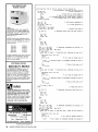
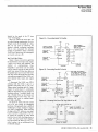
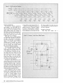
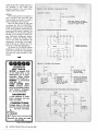
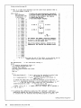
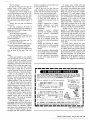
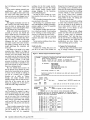
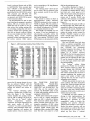
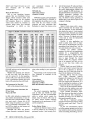
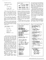
The Kaypro 4-84 Internal
Modem
G. R. Blowers
We were somewhat hard pressed for a Kaypro
column this issue when, 10 and behold, this terse
treatise on the Kaypro's modem came in on our
RBBS. The original file was dated April, 1984, but
the information is timeless.
For those of you doing interesting things with
your Kaypros: think about submitting an article to
Micro C. We'd like to see what you're up to.
his article documents. the internal
modem in the Kaypro 4-84. I got the information by decoding the relevant
parts of ST.COM (provided on the
CP /M disk). Some of the code comes straight
from ST and some is code that I used to test the
various modem functions.
The 4-84's modem is not a smart type (not
Hayes compatible). It consists primarily of two
TI chips-an FSK modem, and a dialer. All
programming and filtering must be done by the
user. The modem makes use of both a parallel
and a serial port. Each of these ports must be
programmed.
T
Port Locations
The parallel port lives at 21h, with its command port at 23h. You'll find the serial port at
ODh, and its command/status port at OFh. The
modem appears to use the normal modem CTC
port of OOH, which needs to be set up for 300
baud (outp(O,5». I'll divide this discussion into
four parts: port bit usage, initialization, modem,
and dialing.
I don't intend to decode ST any further than
I already have. All I want, or need, is enough to
put the internal modem through its paces. Although I can find no copyright notice in
ST.COM, I presume Kaypro considers it
proprietary. Therefore: No commercial use may
be made of this information without prior written consent from Kaypro Corporation.
Parallel Port Bit Usage
The low nibble (bits 0-3) of the parallel port
(21h) is used for dialing. Place the number (not
76
MICRO CORNUCOPIA, #39, lan-Feb 1988
the ASCII) here when dialing. During modem
use, send this nibble a OAh.
Bit 4 sets the dial mode, reset (zero) for tone
and set (one) for pulse. It must be set during
modem operation. Bit 6 specifies off! on hook.
A reset bit 6 means off-hook and set means onhook. Setting bit 7 commands the dialer to do
its thing.
Serial Port Bit Usage
On to the serial status/command port at
OFh. Read Register 0 (RR#O) behaves normally
except for bit 5. Bit 5 seems to be used for ring
detection. It looks at DCD (Data Carrier
Detect).
See Figure 2 for initialization of write
registers 0-4 (WR#0-4).
In WR#5, RTS (Request To Serid) and DTR
(Data Terminal Ready) are important. Setting
RTS enables the modem. With RTS set and
DTR reset, the modem goes to originate mode.
The combination of RTS set and DTR set gives
the answer mode.
The serial data port lies at ODh.
Initialization
The CPU must be initialized to 1M2 and interrupts must be enabled. Then load the interrupt vector, and finally, enter the interrupt service routine. Although the code could be
anywhere, I chose to use the page 0 restart
area. See Figure 1 for the CPU initialization
code and Figure 2 for port initialization.
Modem Use
Figure 3 contains code for operating the
modem. The dialing routine (Figure 4) comes
from ST.COM. I found that a delay was needed
between numbers. The code assumes that
register A contains a valid number. Remember,
this is not the ASCII representation of the number, but the actual binary number, zero through
nine.
All filtering and selection of tone or pulse
mode dialing must be done prior to entering
the dialing loop. I won't go into the detection of
carrier or switching to the modem mode as
they are straightforward. Normal conventions