1
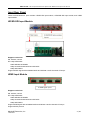
Marshall Electronics MMV‐XXI‐2HD 1RU Multi‐Viewer System (Dual HDSDI Outputs) User Manual V2.0 www.lcdracks.com Table of Contents Description ........................................................................................................................ 1 Features............................................................................................................................ 1 Special Notice ................................................................................................................... 2 Front Panel ....................................................................................................................... 2 Input/ Output Rear Panel .................................................................................................. 3 Input Rear Panel .......................................................................................................... 4 HD/SD-SDI Input Module.................................................................................... 4 HDMI Input Module............................................................................................. 4 CVBS/SD-SDI Input Module ............................................................................... 5 Output Rear Panel ....................................................................................................... 6 Application ........................................................................................................................ 7 How To Use The Remote Control Software....................................................................... 7 Attention Before Use: ................................................................................................... 7 Basic Physical Configuration of MMV-2HD .................................................................. 8 Edit Input Source ................................................................................................ 9 Edit Screens ..................................................................................................... 10 General Configuration .................................................................................................11 Function Overview .............................................................................................11 System Settings................................................................................................ 12 Create a Channel ........................................................................................... 13 Choose Input Source ..................................................................................... 15 Make / Delete Signal Marker .......................................................................... 17 Create Clock / Timer / Logo............................................................................ 18 Delete an Object ............................................................................................ 19 Clear All.......................................................................................................... 19 Screen 1 and Screen 2................................................................................... 20 Quick Tools..................................................................................................... 21 Do & Undo................................................................................................. 21 Alignment Tools ......................................................................................... 21 Full Screen ................................................................................................ 21 Layout Management ...................................................................................... 22 Save Layout .............................................................................................. 22 Edit Layout ................................................................................................ 22 Delete Layout ............................................................................................ 22 Download Layout File................................................................................ 22 Upload Layout File .................................................................................... 22 HDMI Output Resolution ................................................................................ 23 SDI Output Resolution.................................................................................... 23 Audio Monitor Output Select .......................................................................... 24 Frame Layout ................................................................................................. 25 Aspect Ratio................................................................................................... 25 Input Source................................................................................................... 25 Waveform Display .......................................................................................... 25 UMD & Audio Meters Display ......................................................................... 26 Attach to Point................................................................................................ 27 Position and Size ........................................................................................... 27 Set Air Timer................................................................................................... 28 OSD Elements ............................................................................................... 28 UMD Settings ............................................................................................ 29 Tally Settings ............................................................................................. 31 Adjusting the Transparency of Audio and UMD ......................................... 32 Display Settings......................................................................................... 33 Adjust Border Color ................................................................................... 33 Extended Settings .......................................................................................... 34 Set Color Parameters ................................................................................ 34 Serial Port Settings.................................................................................... 34 Timing Settings.......................................................................................... 35 Upload Custom Picture ............................................................................. 36 Channel Style ............................................................................................ 36 Detection Settings............................................................................................. 37 Audio Detection.............................................................................................. 38 Audio Overload.......................................................................................... 38 Audio Silence ............................................................................................ 39 Video Detection .............................................................................................. 39 Loss of Signal............................................................................................ 39 Video Frozen ............................................................................................. 39 Video Black ............................................................................................... 39 Voice Alarm .................................................................................................... 39 User Configuration............................................................................................ 45 Network Configuration ...................................................................................... 45 Help .................................................................................................................. 47 Accessories List .............................................................................................................. 48 Contact Us ...................................................................................................................... 49 Copyright Copyright © November 2011, Marshall Electronics, Inc. All Rights Reserved. This document may not be copied. Trademarks Other trademarks used in this document are registered trademarks or manufacturer or vendor trademarks associated with the products. Disclaimer Product options and specifications can b e changed without notice. The information in this manual is furnished for informational use only and should not b e construed as a commitment by Ma rshall Electronics, Inc. Marshall Electronics, Inc. assumes no responsibility or liability for any errors or inaccuracies that may appear in this publication. MMV‐XXI‐2HD : 1RU Compact Multi‐Viewer System with HDSDI Dual Output User Manual Description MMV-XXI-2HD is a modular multi-viewer system with two high-quality individual outputs. This system is equipped with two output cards and up to four inp ut cards. It su pports up to 16 input signals. One output shares all the sign al sources with the other. Sign als can be a ppointed to any output for display freely . Furthermore, any video channel can be directly and simply moved from one screen to another screen in realtime. HDMI and HDSDI dual output interfaces are provided on each output card. The HDMI re solution is u p to 1920x1080 and HDSDI format is up to 1080p 60. MMV-2HD provides three kinds of input cards: MMV-CVSD input card (4 auto-sensing CVBS/ SDI inputs), MMV-SDHD input card (4 aut o-sensing HD/SD inputs) and MMV-HDI input card (4 HDMI inputs). This modular system allows the user to ea sily construct display systems in a 1RU frame of 4 inputs, 8 inputs, 12 inputs or 16 inputs. The MMV-XXI Montage Series is a multi-view di splay system wit h rich features of hig h-quality, multi-format input, flexible and customizable functions, remote panel, audio monitoring, waveform display, real time monitoring and voice alarm warning, a nd dynamic UMD & tally from routers. It can be widely use d in the studio, broadcasting room, general control center, and production editing studio. The most flexible com bination and feature-rich platform makes it ideal f or many ap plications where video/audio monitoring and displays are required! Features Provides high-quality dual outputs with flexible and individual configuration on each output. Provides three kinds of input cards: MMV -CVSD: CVBS/SDI aut o-sensing input card, MMV -SDHD: HD/SD auto-sensing input card, and the MMV-HDI: HDMI input card. Different multi-viewer display configuration depending on number and type of input card in 1RU frame. Input displays on either output using the flexible configuration panel on the internal web server. Multi-format input combinations can be configured. Flexible output options: 4:3, 16.9, or customized aspect ratio. Editable dual program UMD and 4 channel audio meters display. Several types of timers: air timer, countdown timer, analog clock timer, and digital clock timer. Mark key signal(s) to find in one complicated layout. Supports user-defined border color in each channel separately or ability to cancel border display. Dynamic UMDs & tally from routers and switches via RS232 interface. Supports format display of input signal and AFD information display. Video/audio auto detection and alarming: video loss, video frozen, video black, audio silence, and audio overload with high rate of accuracy. Two alarm forms: text alarm and icon alarm. Supports SNMP. Supports customized layout presets for different applications: studio, OB van, production room, etc. Standard 1RU frame with dual power supply. Marshall Electronics, Inc 11/22/2011 1 / 49 MMV‐XXI‐2HD : 1RU Compact Multi‐Viewer System with HDSDI Dual Output User Manual Special Notice 1. In order to avoid network traffic congestion, please do not submit new parameters before the last modification has been applied. 2. Generally, it take s about three seconds to get resu lts after yo u submit a command. T he time is related with the monitor type. 3. Do not plug-in the HDMI connector without power-down. 4. Without the professional technological guidance from Marshall Electronics, users are not permitted to replug the mo dules away from the cha ssis or d ebug the internal operation. Marshall Ele ctronics is n ot responsible for damage caused by unauthorized or incorrect module installation. 5. Easily control the MMV via Ethernet connectivity on your computer. The MMV IP address should be in the same network segment as your computer. The MMV IP and Mac address should be a unique value. 6. Windows 2003, Windows XP, Windo ws Vista a nd Windows 7 a re strongly recommended with Intern et Explorer.exe. 7. User can also upgrade system under the label “Network”. Before the upgrade, the anti-virus software and firewall must be closed to make sure that the upgrade data is transmitted to the MMV-2HD system without rejection. Power and network connections can not be interrupted during a system upgrade. 8. Please set all channels to input inner test signal without waveform display before upgrade. This will reduce the time to upgrade the system. 9. If the cu rrent output resolution of HDMI signal is not compatible with your monitor, you can change the output resolution on the web control server. Front Panel Reset Button: Located in the small hole on the front panel. This function is used to restore the factory value IP address and user password (192.168.1.76 & 000000). Insert a push pin to the small hole and press the button until there is no picture from HDMI and HD/SD-SDI output. The device will restart with the default IP address and user password. Marshall Electronics, Inc 11/22/2011 2 / 49 MMV‐XXI‐2HD : 1RU Compact Multi‐Viewer System with HDSDI Dual Output User Manual Input/ Output Rear Panel Slot A Slot C Slave Output XLR Interface Slot B Slot D Main Output RS232 Serial Port There are six slots for input and output cards. For dual output display system, two output cards are used: main output card and slave output card. See the picture above. The dual outputs are configured by the web server with the network inte rface (RJ45) on m ain output ca rd. The default IP address is 19 2.168.1.76. The RJ45 interface on slave output card is invalid with no function. Four slots remain for input card. Ea ch slot has an attribute. From bottom to t op and left to right, these slots are named as Slot A, Slot B, Slot C and Slot D. When one input card is inserted into Slot A, up to four virtual channels can be created from this input card as a channel group named group A. This applies to Slot B, C an d D as well. Input signals can only be displayed on virtual channels created from the same input card. XLR Interface is for LTC timing. The definition is shown below: Pin 1—GND Pin 2—LTC+ Pin 3—LTC‐ 1 3 2 MMV-XXI-2HD is EBU code according to IEC standard. The pin 1 is GND and pin 2 & 3 receive LTC data. Check the “LTC” box on the web page to enable the LTC timing. See the picture below for details. RS232 Serial Port is for GPS Timing, Dynamic UMD & Tally and Layouts Remote. RS232, DB9 definition (For TSL and GPS) Pin Function 2 Rx 3 Tx 5 GND RS232 to RS232 Cable Connection 2------------------------3 3------------------------2 5------------------------5 Marshall Electronics, Inc 11/22/2011 3 / 49 MMV‐XXI‐2HD : 1RU Compact Multi‐Viewer System with HDSDI Dual Output User Manual Input Rear Panel There are three kinds of i nput modules: HD/SD-SDI input modul e, CVBS/SD-SDI input module, and HDMI input module. HD/SD-SDI Input Module Support resolutions: SD: 480i 60, 576i 50 HD: 720p 50Hz/60Hz 1080i 50Hz/59.94Hz/60Hz 1080p 23.976Hz/24Hz/25Hz/29.97Hz/30Hz 1080p 50Hz/60Hz Support HD/SD signal with embedded audio and indicate 4 audio channels of Group1. HDMI Input Module 4 HDMI signal inputs Support resolutions: SD: 480i 60, 576i 50 HD: 720p 50Hz/60Hz 1080i 50Hz/59.94Hz/60Hz 1080p 23.976Hz/24Hz/25Hz/29.97Hz/30Hz 1080p 50Hz/60Hz Support HDMI signal with embedded audio and indicate 4 audio channels of Group1. Support HDCP protocol. Marshall Electronics, Inc 11/22/2011 4 / 49 MMV‐XXI‐2HD : 1RU Compact Multi‐Viewer System with HDSDI Dual Output User Manual CVBS/SD-SDI Input Module The Audio/Tally input module supports 1 audio channel for each analog video input. Support formats: CVBS : NTSC/Pal SDI : 480i 60/576i 50 Support SDI signal with embedded audio and indicate 4 audio channels of Group1. Marshall Electronics, Inc 11/22/2011 5 / 49 MMV‐XXI‐2HD : 1RU Compact Multi‐Viewer System with HDSDI Dual Output User Manual Output Rear Panel Each output module provides HDSDI and HDMI dual outputs. The output module provides an HDMI input and RJ45 interface for web server. Network: RJ45 interface with 10/100/1000M auto-detection. The dual outputs are configured by web server with the network interface (RJ45) on main output card. The default IP address is 192.168.1.76. When the output card is on the left side facing the rear panel of the frame, it is a slave output card. The RJ45 interface on the slave output is invalid without function. Slot A Slave Output Slot C Slot D Slot B Main Output HDMI OUT: Two channel HD/SD-SDI audio signals, eight channel HDMI audio signals, or one channel analog audio can be embedded into the HDMI output signal. Users can select audio source via the web control to m onitor audio signals embedded into HDMI output si gnal. The output resolution of HDMI signal is up to 1920x1080. The output resolutions are listed below: 1024x768, 1280x720, 1280x768 1280x1024, 1360x768, 1400x1050 1600x1200, 1680x1050, 1920x1080 HDMI IN: An HDMI input interface is provided on each output card. When the HDMI interface input is non3G signal, the channel can display audio meters, UMD, input resolution, safe area, etc. When the HDMI interface input is 3 G signal (1080p 50/59.94/60), the ch annel only di splays UMD. The HDMI input channel is either above or below all the channel input modules. The input resolutions are listed below: SD: 480i 60, 576i 50 HD: 720p 50Hz/60Hz 1080i 50Hz/60Hz 1080p 24Hz/25Hz/30Hz 1080p 50Hz/60Hz HDSDI OUT: There is an HD/SD-SDI output interface on the output module. The embedded audio signals of HD/SD-SDI output signal are the same as the ones of HDMI output signal. The output format can be configured via web server to fixed value below: 576i 50/480i 59.94 720p, 1080i, 1080p Marshall Electronics, Inc 11/22/2011 6 / 49 MMV‐XXI‐2HD : 1RU Compact Multi‐Viewer System with HDSDI Dual Output User Manual Application MMV-2HD can be applied in the Studio System with two individual outputs from a single device. The signal source can be assigned to any output. MMV-2HD can be appli ed in a Produ ction Station. A single device can be used in two dif ferent rooms for monitoring at same time. The signal source can be assigned to any output. How To Use The Remote Control Software Attention Before Use: MMV-2HD has built-in Web Server; user can configure via Internet Explorer easily if connected through cable. First Step: Login to 192. 168.1.76/config.html and o pen physical configuration of MMV-2HD: Input Source Name Editing and Screen Position Settings. Second Step: Login to 192.168.1.76 and open general web control. There are several web labels: System, Alarm, User, Network, and Help. The default IP address: 192.168.1.76. The default user name: admin The default password: 000000 Marshall Electronics, Inc 11/22/2011 7 / 49 MMV‐XXI‐2HD : 1RU Compact Multi‐Viewer System with HDSDI Dual Output User Manual Basic Physical Configuration of MMV-2HD Open Internet Explorer and input http://192.168.1.76/config.html to open web page of Physical Configuration. The page is shown below: Marshall Electronics, Inc 11/22/2011 8 / 49 MMV‐XXI‐2HD : 1RU Compact Multi‐Viewer System with HDSDI Dual Output User Manual Edit Input Source Edit name of input source for each input card on left side of web page. HDMI Input signal from main output card HDMI Input signal from slave output card 4 Input signals from input card inserted Double click each bar to edit individual name for each input source 4 Input signals from input card inserted 4 Input signals from input card inserted 4 Input signals from input card inserted Rear Panel: Slot A Slave Output Slot C Slot D Slot B Main Output Relationship between Input Source and Inserted Slots: Slot Module Type Interface on the rear Channel Name on Web page M HDMI In on Main output card HDMI IN M1 S HDMI In on Slave output card HDMI IN S1 A Input card inserted in Slot A CH1, CH2, CH3, CH4 Group A: A1, A2, A3, A4 B Input card inserted in Slot B CH1, CH2, CH3, CH4 Group B: B1, B2, B3, B4 C Input card inserted in Slot C CH1, CH2, CH3, CH4 Group C: C1, C2, C3, C4 D Input card inserted in Slot D CH1, CH2, CH3, CH4 Group D: D1, D2, D3, D4 Note: 1. Interfaces named CH1~CH4 on rear panel of input card inserted into Slot A are corresponding to A1~A4 on Web. So does Group B, C and D 2. If there is no input card inserted into certain slot, like Slot A, the related channel group, that is channel group A, will not be shown on the web page. Marshall Electronics, Inc 11/22/2011 9 / 49 MMV‐XXI‐2HD : 1RU Compact Multi‐Viewer System with HDSDI Dual Output User Manual Edit Screens Display IP Address Arrangement Mode Editing Buttons Display Area Display IP address: Shows the IP address for dual output system in the location bar; read only. Editing Buttons: Create, Delete, and Release. Create: Creates a screen. Maximum of two screens can be created. Del: Deletes an existing screen. Release: Releases current name of input sources and arrangement of screens. Jumps to web page 192.168.1.76. Arrangement Mode: To arrange the position of scre ens; based on a ctual physical position of monit ors connected to the MMV-2HD. Screen 1 is the HDMI output signal of main output card. Screen 2 is the HDMI output signal of slave output card. : Screen 1 is left and Screen 2 is right. : Screen 2 is left and Screen 1 is right. : Screen 1 is up and Screen 2 is down. : Screen 2 is up and Screen 1 is down. Marshall Electronics, Inc 11/22/2011 10 / 49 MMV‐XXI‐2HD : 1RU Compact Multi‐Viewer System with HDSDI Dual Output User Manual General Configuration You do not need to install the client software. Open Internet Explorer and enter the IP address in the location bar to open the user interface. Default IP address is: http://192.168.1.76. Login Interface: Enter user name: admin and initial code: 000000. Click “Login” to enter actual operation remote control. Function Overview The following function options can be located on the top menu bar of the web page: System, Alarm, User, Network, and Help. System: Designs the output display layout via creating or deleting windows, clock, logo, UMD and other display elements. Alarm: The system detects audio, mute, frame frozen, black, signal l oss, EDH detection. Each ala rm threshold can be programmed to meet your needs. User: The system supports user name called admin. The initial password i s 000000 which can be changed. The new password will take effect during next log in. Network: Modifies the IP address and upgrades the firmware. The modification will take effect after machine has been restarted. Help: Shows all versions of firmware here. Marshall Electronics, Inc 11/22/2011 11 / 49 MMV‐XXI‐2HD : 1RU Compact Multi‐Viewer System with HDSDI Dual Output User Manual System Settings You can set the ba sic configuration in the System Setti ngs which includes the following functions: create or delete the channels, add the clock and logo, align selected channels via th e quick tools, undo the previous operations, and set the p arameters such as output resolutions, aspect ratio, and extend ed configuration. Click the submit button to take effect after configuration is selected. See details below: Marshall Electronics, Inc 11/22/2011 12 / 49 MMV‐XXI‐2HD : 1RU Compact Multi‐Viewer System with HDSDI Dual Output User Manual Create a Channel The system detects the name of input source for each input card and makes a list according to the settings on the Physical Configuration page. If no input card is in serted in a slot (Ex: Slot A), the related channel group (Ex: Channel Group A) will not be shown on the web page. Each channel group has their own color box. Click the col or box to crea te channel M1. This color is c olor ID of Channel M. Click the col or box to crea te channel S1. This color is c olor ID of Channel S. Click the col or box to creat e channel A1, A 2, A3 and A4. This color is color ID of Channel group A. HDMI signal source from HDMI input interface of Main output card HDMI signal source from HDMI input interface of Slave output card Signal sources from interface (CH1 t CH4) of input card inserted into Slot A o Signal sources from interface (CH1 t CH4) of input card inserted into Slot B o Click the color box to cr eate channel C1, C2, C3 and C4. This color is color ID o f Channel group C. Signal sources from interface (CH1 t CH4) of input card inserted into Slot C o Click the color box to cr eate channel D1, D2, D3 and D4. This color is color ID o f Channel group D. Signal sources from interface (CH1 t CH4) of input card inserted into Slot D o Click the color box to cr eate channel B1, B2, B3 and B4. This color is color ID o f Channel group B. Steps to Create a Video Channel: Step 1- Click the color box of a channel group. For Example: Click color box Channel M. Marshall Electronics, Inc 11/22/2011 13 / 49 MMV‐XXI‐2HD : 1RU Compact Multi‐Viewer System with HDSDI Dual Output User Manual Step 2- Hold the mouse a nd drag from top to botto m of the target screen to create the frame. Step 3- Release the mouse. The system will create a Channel M1 with the size and position of the frame. You ca n change the si ze and position of the channel as needed. Channel M1 is shown below: Channel ID Name of Input Source The unique Channel ID i s shown on each channel. The input source name is di splayed on the current channel. Channel Colors distinguish the various channels from one another. Marshall Electronics, Inc 11/22/2011 14 / 49 MMV‐XXI‐2HD : 1RU Compact Multi‐Viewer System with HDSDI Dual Output User Manual Choose Input Source HDMI signal source from HDMI input interface of Slave output card. It only can be displayed on Channel S1. HDMI signal source from HDMI input interface of Main output card. It only can be displayed on Channel M1. Signal sources from interface (CH1 to CH4) of input ca rd inserted into Slot A. They only can be displayed on their own group, that is, channel A1, A2, A3 and A4. Signal sources from interface (CH1 to CH4) of input card inserted into Slot B. They only can be displayed on their own group, that is, channel B1, B2, B3 and B4. Signal sources from interface (CH1 to CH4) of input card inserted into Slot D. They only can be displayed on their own group, that is, channel D1, D2, D3 and D4. Signal sources from inte rface (CH1 to CH4) of i nput card inserted into Slot C. They only can be displayed on their own group, that is, channel C1, C2, C3 and C4. The input signal sources from each input card can only be displayed on its own four channels; Input signals and channel group are joined together. Marshall Electronics, Inc 11/22/2011 15 / 49 MMV‐XXI‐2HD : 1RU Compact Multi‐Viewer System with HDSDI Dual Output User Manual Steps to Assign Input Source to Video Channel: Step 1- Use the mou se to cho ose one input source in the l ist and drag out (Ex: “HD Server1” from Chan nel GroupA). Step 2- Drag the signal out of the list until it is p ositioned on t he target channel and release the mouse. (Signal so urce and selected channel must belong to the same group.) Channel A1 currently displays source as “HD Server1”. Marshall Electronics, Inc 11/22/2011 16 / 49 MMV‐XXI‐2HD : 1RU Compact Multi‐Viewer System with HDSDI Dual Output User Manual Make / Delete Signal Marker The key signal will be shown in a red font while the displayed channel will be marked with a red border so it can be located quickly in a complicated layout, even after a series of position adjustments. Note: Multiple signals can be marked at the same time. The name of the marke d source is sh own in a red font. The selected channel using the signal as the curren t display so urce appears with a red border not only o n the web but on the actu al output as well. The signal marker can be removed by using the “Delete Marker” button. Select the input source in the list and click “Mark Source”. For Example: “HD Keyer” from Group C. Marshall Electronics, Inc 11/22/2011 17 / 49 MMV‐XXI‐2HD : 1RU Compact Multi‐Viewer System with HDSDI Dual Output User Manual The display channel using the source signal will appear on the actual output with a red border. Create Clock / Timer / Logo The following objects can also be created. These options are located on the sub-menu bar: Analog Clock, Digital Timer, Count-down Timer, Air Timer, and Logo. Two objects in each category can be created but only one object can exist on the screen at a time. The size of Digital Timer, Count-down Timer, and Air Timer can be changed as needed. The size of Logo and Analog Clock cannot be changed. Step 1- Click the o bject to be cre ated. For Example: click the “Analog Clock” button to create an analog clock. Step 2- Hold the mouse and drag from top to bottom on the target scre en to create the frame for the object. Marshall Electronics, Inc 11/22/2011 18 / 49 MMV‐XXI‐2HD : 1RU Compact Multi‐Viewer System with HDSDI Dual Output User Manual Step 3- Release the mouse. The system then creates the object in the position of the frame with a fixed size. You can move the position of the object as needed. (Ex: Analog Clock shown here) Note:The time can be customized for the Air Timer. The details are shown below: Air Timers on each screen can be configured individually. First, click the target screen and press the “Set Air Timer” button. A pop-up message box will appear and the time can be entered. Enter the numbers for each box separately. Press “O K” to submit and save the data. The countdown timer is the interval time between air timer and the current timer. Delete an object Select an i ndividual, unnecessary object (Channel / Clock / “ Timer / Logo) and then press the button ”. The selected object will be deleted immediately. The hot key is “Delete” on the keyboard. Clear All Each screen can be cleared in full with one command. Click the selected screen and then press the button “ ” to clear all the objects from the current screen. Marshall Electronics, Inc 11/22/2011 19 / 49 MMV‐XXI‐2HD : 1RU Compact Multi‐Viewer System with HDSDI Dual Output User Manual Screen 1 and Screen 2 Screen 1 is the HDMI out put signal of main outp ut card. Screen 2 is the HDM I output signal of slave out put card. The position of the two screens can be configured as needed. See instructions in the Basic Physical Configuration section (Edit Screen / Arrangement Mode, page 10). Various functions are available in this menu. Main functions are listed below: 1. Display all the channels, clock, timer and logo. 2. Adjust the position of the clock and logo by dragging the edge with the mouse. 3. Adjust the position and size of the channels by dragging the edge with the mouse. 4. Adjust the position and size of au dio meters and UMD of each channel by dragging the edge of each audio meter or UMD with the mouse. 5. Select one or more objects in this area before changing parameters or taking further actions. 6. Video channels can be moved from one screen to another screen in real time. Each screen can be magnified to full screen size for easy editing. All operations in this area are displayed on the monitor or LCD in real time. Maximize Screen 1 Maximize Screen 2 Restore Two Screens Marshall Electronics, Inc 11/22/2011 20 / 49 MMV‐XXI‐2HD : 1RU Compact Multi‐Viewer System with HDSDI Dual Output User Manual Quick Tools There are various quick tools for creating various layouts. Do & Undo : Undo, hotkey is “Ctrl+Z”; : Do, hotkey is “Ctrl+Y”. Alignment Tools All operations among these windows are aligned to the last selected one. : Align Top : Align Bottom : Align Left : Align Right : Align Horizontal Center : Align Vertical Center : Horizontal Average : Vertical Average : Overspread with Horizontal Equal Width : Overspread with Vertical Equal Height The buttons below are not only for channels but for UMD & Audio Meters as well. The selected audio meter is adjusted according to another one in the same channel. The buttons below can’t be applied to audio m eters from different channels. : Equal Width : Equal Height : Equal Width & Height. Except for the alignment tools above, this software supports hotkeys on the keyboard, such as direction key “ ” to move channels in this area. Full Screen Choose one channel and double click it. The selected channel will output in full screen mode. When you want to quit the full screen mode, please use hot key “Ctrl+Z” or click Marshall Electronics, Inc 11/22/2011 . 21 / 49 MMV‐XXI‐2HD : 1RU Compact Multi‐Viewer System with HDSDI Dual Output User Manual Layout Management The system allows customers to save multiple user- defined layouts. The max number of layouts is 10 fo r the customer. Layouts can be applied and saved at any time. Save Layout Enter the name of layout in the blank area and click the “Save” button. The layout is saved as a thumbnail in the layout management area. The layouts on both screens are saved at the same time. Click the thumbnail to apply the relevant layout. If the name of the layout already exists, the new layout will be saved in place of the old layout. Edit Layout Click the selected thumbnail layout and adjust as needed. After completion, click the “Save” button. Delete Layout : Delete Button Click the delete button on the top of the selected layout thumbnail to delete the unnecessary layout. Download Layout File Click “Download” button and save the designed layouts as a BIN file. All the layouts in this area are saved as one file and can not be downloaded individually. Upload Layout File Click the “Browse” button to find and upload the current layouts. A me ssage box will appear after layout has been successful uploaded. Please refresh the p age so the layouts will appear in layout disp lay area as new thumbnails. Apply a layout by clicking its relevant thumbnail. NOTE: The most recently uploaded layout will replace the original one. Marshall Electronics, Inc 11/22/2011 22 / 49 MMV‐XXI‐2HD : 1RU Compact Multi‐Viewer System with HDSDI Dual Output User Manual HDMI Output Resolution HDMI output interface provides EDI D detection from the moni tor. And the re solutions from EDID are highlighted in the dropdown list. See the picture shown above. The output resol ution of HDMI signal has a maximum resolution of 1920x1080. Select a sp ecific screen and then cho ose the outp ut resolution for the HDMI signal in the drop-down list. (Screen 1 is from main output card and Screen 2 is from slave output card.) 1024x768, 1280x720, 1280x768 1280x1024, 1360x768, 1400x1050 1600x1200, 1680x1050, 1920x1080 SDI Output Resolution HD/SD-SDI and HDMI inte rface produce output si gnals at the same time with the sam e video content and embedded audio for each output card. The SDI output fo rmat is different from HDMI output signal which can be set independently. Select a specific screen and choose the output resolution for the HD/SD-SDI signal in the drop-down list. (Screen 1 is from main output card and Screen 2 is from slave output card.) None 576i 50/480i 60 720p 1080i 1080p Marshall Electronics, Inc 11/22/2011 23 / 49 MMV‐XXI‐2HD : 1RU Compact Multi‐Viewer System with HDSDI Dual Output User Manual Audio Monitor Output Select Channels located on Screen1 in the drop‐down list Choose Screen 1 and select one of th e channels located on Screen 1 in the drop-down list. HD/SD-S DI audio signals will be displayed on the selected channel and will be embedded into HDMI and HD/SD on the main output card signal. Fo r Example: When selecting Channel D2, input audio signals displayed on Channel D2 are embedded into HDMI and HD/SD on the main output card signal. Channels located on Screen2 in the drop‐down list Choose Screen 2 and select one of th e channels located on Screen 2 in the drop-down list. HD/SD-S DI audio signals will be displayed on the selected channel and will be embedded into HDMI and HD/SD on the slave output card signal. For Example: When sel ecting Channel D3, input audio si gnals displayed o n Channel D3 are embedded into HDMI and HD/SD on the slave output card signal. The audio for a specific channel is re ached by monitoring the embedded audio of the HDMI or HD/SD-SDI output signal. A, When the input source is HD/SD-SDI signal, two channel HD/SD-SDI audio signals can be embedded into the HDMI and HD/SD-SDI output signal. B, When the input source is HDMI signal, up to eight channel HDMI audio signals can be embedded into the HDMI and HD/SD-SDI output signal. C, When the input source is CVBS signal, one channel analog audio signals can be embedded into the HDMI and HD/SD-SDI output signal via the audio/Tally input module. Marshall Electronics, Inc 11/22/2011 24 / 49 MMV‐XXI‐2HD : 1RU Compact Multi‐Viewer System with HDSDI Dual Output User Manual Frame Layout There are two types of video display: Full Channel and Original Proportion. Full Channel means the video image will cover the entire channel and ignore the aspect ratio of video signal. Original Proportion means the video image always keeps the aspect ratio of video sign al even though the ratio of the channel or the size of UMD and Audio meters can be changed. For SD input signal, the aspect ratio of video image is 4:3. For HD input signal, the aspect ratio is 16:9. Aspect Ratio Aspect Ratio channel options are 4:3, 16:9, and Free Ratio. 4:3-The channel size will always keep the aspect ratio of 4:3. 16:9- The channel size will always keep the aspect ratio of 16:9. Free Ratio- The size of channels can be changed to any specific aspect ratio. Input Source Select the video type between the External Signal (HD/SD-SDI) and the test signal generated by the system. Waveform Display MMV-2HD supports the display of re al-time waveform. Cli ck the drop-down list to vie w three o ptions: None, Waveform One and Waveform Two. Waveform One (from top to bottom): Y waveform, PbPr waveform, and Vector; Waveform Two (from top to bottom): Y waveform, Audio waveforms of G 1 CH1, and Audio phase of G1 CH1& CH2. None means there are no waveforms on the image. No audio meters will be associated with this display. Marshall Electronics, Inc 11/22/2011 25 / 49 MMV‐XXI‐2HD : 1RU Compact Multi‐Viewer System with HDSDI Dual Output User Manual Waveform One: Waveform Two: UMD & Audio Meters Display Check the “ UMD” and it will be sh own within the channel. Th e system supports dual UMD displays. The UMD can be configured with the “OSD Elements” button located on the bottom-right side of web page. Check the “CH1&2” box to display the audio meters of CH1 and CH2 with HD/SD signal. Check the “CH3&4” box to display the audio meters of CH3 and CH4 with HD/SD signal. Check the “Locked” box to lock the audio meters and UMD within that window. The audio meters and UMD can’t be operated separately when locked. Marshall Electronics, Inc 11/22/2011 26 / 49 MMV‐XXI‐2HD : 1RU Compact Multi‐Viewer System with HDSDI Dual Output User Manual Attach to Point When checking the “Attached to Point” box, a grid will appear on both screens. Objects can be moved or adjusted by aligning to a point or line within the grid. Grid settings can be customized to change the row and column width and density. When box is not checked, the two screens are blank and objects can be moved and adjusted as needed. Position and Size The values of the chann el’s coordinates (height and width) a re shown on th e right of web page when an object is selected. These are read only and can not be adjusted in this menu. Marshall Electronics, Inc 11/22/2011 27 / 49 MMV‐XXI‐2HD : 1RU Compact Multi‐Viewer System with HDSDI Dual Output User Manual Set Air Timer Air Timers in each scree n can be conf igured separately. First, click the targ et screen a nd press “Set Air Timer” button and a pop-u p window will appear. See t he picture above. Enter the numb ers in the Ho ur, Minute, and Second boxes individually. Press “OK” to submit the data. The countdown timer is the inte rval time between air timer and current timer. OSD Elements Click the “ ” button for the following options: Marshall Electronics, Inc 11/22/2011 28 / 49 MMV‐XXI‐2HD : 1RU Compact Multi‐Viewer System with HDSDI Dual Output User Manual UMD Settings Select the ap propriate channel from th e drop-down list. The syst em supports single or d ual program UMD displays. Dual UMD is composed of left UMD and right UMD. A white dash separates the left and right UMD text. Left UMD Right UMD These can be configured separately. UMD text can be edited via network or serial port. Network-Static UMD Choose “Network” in the drop-down list and click “Settings”. Upload UMD Text Type the cha racters in the Input Cha racter field a nd select text color. When all parameters have be en set, click “OK” to save. All characters will be displayed in the UMD. To Clear the UMD Enter a “space” and then click “OK”. All the characters in the UMD area will be deleted. Marshall Electronics, Inc 11/22/2011 29 / 49 MMV‐XXI‐2HD : 1RU Compact Multi‐Viewer System with HDSDI Dual Output User Manual Serial Port (RS232)-Dynamic UMD Choose “Serial Port” in the drop-down list and click “Settings”. Steps for Dynamic UMD: First: Set the baud rate and parity. The baud and parity must be the same as the TSL Tallyman. Second: Check the "TSL” box to enable the Dynamic UMD function. Third: Set the target address for selected channel to receive the data from TSL Tallyman. To view more details, please see the serial port configuration section under “Extended Settings”, page 34. Please make sure target address for single o r dual UMDs are different; each target address has a unique value, even for right and left UMD of dual UMD display. NOTE: Multiple strings for TSL functions can be at the same time. Maximum Strings = 10. RS232, DB9 Definition (For TSL and GPS) Marshall Electronics, Inc 11/22/2011 Pin Function 2 Rx 3 Tx 5 GND 30 / 49 MMV‐XXI‐2HD : 1RU Compact Multi‐Viewer System with HDSDI Dual Output User Manual Protocol V3.1 Dynamic UMD Protocol ---------------------------------------------------------------| HEADER | CONTROL BYTE | DISPLAY DATA | ---------------------------------------------------------------Header = Display Address (0-126) + 80 hex (1 byte) (Control byte and display data will be sent) Control (1 byte) bit 0 = tally 1 (1=on, 0=off) bit 1 = tally 2 (1=on, 0=off) bit 2 = tally 3 ( 1=on, 0=off ) bit 3 = tally 4 ( 1=on, 0=off ) bits 4-5 = brightness data bit 4 = 0, bit 5 = 0 (0 brightness) bit 4 = 0, bit 5 = 1 (1/7 brightness) bit 4 = 1, bit 5 = 0 (1/2 brightness) bit 4 = 1, bit 5 = 1 (full brightness) bit 6 = reserved (clear to 0) bit 7 = cleared to 0 Display Data (16 bytes) = 16 displayable ASCII characters in the range 20 hex to 7E hex. All 16 characters must be sent. Tally Settings First, select the appropriate channel in the drop-down list. Second, check the box to enable the Tally Display function. The system supports single Tally display. Tally options are GPI or Serial Port. GPI-Static Tally Choose “GPI” in the drop-down list to enable Static Tally. Static Tally is applied with the Tally input module below: Marshall Electronics, Inc 11/22/2011 31 / 49 MMV‐XXI‐2HD : 1RU Compact Multi‐Viewer System with HDSDI Dual Output User Manual "Static Tally” should be checked when there is a high level input and the TALLY area will turn light or dark red, depending on the level. If it’s not checked, no matter what the input level, t he TALLY area will turn gray. Voltage higher than 3.3V and lower than 7V is considered high level input. Users can choose the modified channel from drop-down list shown below: "Static Tally” Not Checked, the tally area is gray: "Static Tally” Checked without high level input, the tally area is dark red: "Static Tally” Checked with high level input, the tally area is light red: Serial Port (RS232)-Dynamic Tally Choose “Serial Port” in the drop-down list to enable Dynamic Tally. When “Dynamic Tally” is checked, the tally is implemented with Dynamic UMD of both single UMD and dual UMD. The current color of Tally is changed based on the latest operation of Dynamic UMD. Tally 1=Red. Tally 2=Yellow. Adjusting the Transparency of Audio and UMD Choose the target channel or all channels from the drop-down list. In this area, users can modify the transparency of audio meters or UMD of each channel. Select the channel to be mo dified and slide the poi nter to the assig ned position. Or you can manually enter the parameter settings ranging from 0 to 255. “0” stands for full transparency and “255” stands for opacity. Attach to Edge Check “Attach to Edge” box when the audio meters and the UMD are located at the b ottom edge of the image. When this is checked, the audio meters and the UMD are aligned to the edge with image in full view. If this box is not selected, the UMD and audio meters may overlap the images. Marshall Electronics, Inc 11/22/2011 32 / 49 MMV‐XXI‐2HD : 1RU Compact Multi‐Viewer System with HDSDI Dual Output User Manual Display Settings Choose the target channel or all channels from the drop-down list. Check the “ AFD Information” box and AFD information will b e overlaid on the top of the channel. AFD information is shown in the form of a picture according to the AFD code inside input signal. Check the “ Input Resolution” box and input resol ution will be overlaid on the top of the channel. In put resolution is shown as 480i 60/525i 50/720p/1080i/1080p. 1080i Check the "Underscan" box to see in selected channels. Check the “ Safe Areas” box and SD-SDI pi cture signal is m arked with 16:9 safe a rea markers; HD-SDI picture signal is marked with 4:3 safe area markers. Check the “Border” box and the selected channel is shown with a border. Border color can be modified. Adjust Border Color Choose the target channel or all chan nels from the drop-down list and cli ck “Modify”. On the color palette, select the appropriate color and click “OK”. The current border color will be changed to the selected color. Marshall Electronics, Inc 11/22/2011 33 / 49 MMV‐XXI‐2HD : 1RU Compact Multi‐Viewer System with HDSDI Dual Output User Manual Extended Settings Set Color Parameters Luminance: To set the brightness and darkness of the picture. The range is from -512 to 511. Saturation: To set the color of the picture. The range is from 0 to 511. Contrast: To adjust the clarity of the picture. The range is from 0 to 511. DeNoise: To remove digital artifacts. The range is from 0 to 63. Restore Default Button: To restore the factory default settings. Serial Port Settings There are three functions provided by the MMV-2HD system via RS232 interface: RS232 Timing, TSL UMD & Tally, and Layout Remote Control. Marshall Electronics, Inc 11/22/2011 34 / 49 MMV‐XXI‐2HD : 1RU Compact Multi‐Viewer System with HDSDI Dual Output User Manual Serial Port Setting Steps: First: Set the baud rate and parity. The baud and parity must be the same as the RS232 devices such as TSL TallyMan. Second: Check the "TSL”, “GPS” or “Template” box to enable this fun ction. O nly one function can be selected because they share the same RS232 interface. Third: For TSL UMD & Tally, select the “Serial Port” in the drop-down list under “UMD Settings” on the OSE Elements menu. Set a ddress for t arget channel to receive the data from TSL TallyMan. GPS Timing and Layout Remote Control do not need this third step. NOTE: Multiple strings for TSL functions can be at the same time. Maximum Strings = 10. RS232, DB9 Definition (For TSL and GPS) Pin Function 2 Rx 3 Tx 5 GND RS232 Cable Connection 2------------------------------3 3------------------------------2 5------------------------------5 “Template” for Layout Remote Control is reserved. Timing Settings There are four kinds of timing modes: LTC Timing, GPS Timing, Local Timing, and NTP Timing. Only one timing mode can be selected at a time. See details of each mode below: LTC Timing means timing is b ased on LTC code via XLR interface. The LTC of MMV-2HB is EB U code according to IEC standard. The pin 1 is GND and pin 2 & 3 receive LTC data. Check the “LTC” box to enable. 1 3 Pin 1—GND Pin 2—LTC+ Pin 3—LTC‐ 2 Marshall Electronics, Inc 11/22/2011 35 / 49 MMV‐XXI‐2HD : 1RU Compact Multi‐Viewer System with HDSDI Dual Output User Manual GPS Timing means the analog clock and digital timer are controlled by GPS timer via RS232 interface. Check the “GPS” box to enable. Baud rate and parity should be configured appropriately. Two “GPS” options are bound together. Check one and the other box is automatically checked. NTP Timing means the analog clock and digital timer are set by NTP Server through RJ45 interface. This supports Network Time Protocol (NTP). The IP address of the NTP Server should be configured in the same network segment as MMV. Configure the “NTP Server” labeled “Network”. Check the “NTP” box to enable. Local Timing means the analog clock and digital timer are controlled by a computer which can also access the web control of MMV-2HD through RJ45 interface. There are two items that required attention: First, the lo cal IP address of this computer should be configured in the same network segment as MMV. Second, refresh the web page after checking the “Local” box to enable and sub mit the current time of computer to MMV. The factory timing mode is the local time. MMV-2HD has a bu ilt-in battery-backed clock so it keeps time when the MMV-2HD is powered down. The battery-backed clock stores the GPS or LTC time code, not Local or NTP. Upload Custom Picture The background, logo, and UMD picture of each channel can be customized through this function. Picture upload must be 32bits TGA format with Alpha channel. The size of the pi cture is 720x60 pixels for UMD and 960X540 pixels for the backgrou nd. The logo picture must be less than 500K B and shoul d be 32bits TGA format with Alpha channel. Channel Style This “ ” button is invalid without function. Marshall Electronics, Inc 11/22/2011 36 / 49 MMV‐XXI‐2HD : 1RU Compact Multi‐Viewer System with HDSDI Dual Output User Manual Detection Settings : : All channel boxes will be selected : The current channel will not be selected while all the others are selected Can : : : cel all channel selections Restore factory settings All channel detection settings will be selected Can cel all channel detection setting selections MMV-2HD provides two kinds of warning modes: texts and small icons. Only one mode can be selected at a time. Text is shown at the bottom of each channel. Video warning icon is shown at left edge of each channel while audio warning is located at the right edge. Marshall Electronics, Inc 11/22/2011 37 / 49 MMV‐XXI‐2HD : 1RU Compact Multi‐Viewer System with HDSDI Dual Output User Manual The video and audio input of each channel can report signal status and validity (with text and icons): (1) Loss of signal: and (2) Video frozen: and (3) Video black: and (4) Audio overload: and (5) Audio in silence: and Several channels can be configured at the same time. If the detection parameters of each channel differ, the configuration should be completed separately. Audio Detection Measuring digital audio units is dBFS (dB Full Scal e). 0dBFS is t he maximum audio level corresponding to +24dBu analog audio. Audio Overload A warning picture will appear when the audio level reaches the maximum programmed threshold. Up to four audio channels will be mo nitored only when checkboxes are selected. The audio threshold and duration of detection can be configured for each audio channel. The threshold in this case is the m aximum audio level. When the actual volume is above this threshold, the system will show an audio overload warning. Marshall Electronics, Inc 11/22/2011 38 / 49 MMV‐XXI‐2HD : 1RU Compact Multi‐Viewer System with HDSDI Dual Output User Manual Audio Silence A warning picture will appear when the audio level falls below the programmed threshold. Up to four a udio channels will be m onitored only when checkboxes are selected. The audio threshold and duration of detection can be configured for each audio channel. The threshold in this case is the minim um audio level. When actual volume is below this threshold, the system will show an audio silence warning. Video Detection Loss of Signal A warning picture will appear when signal is lost. Signal will be monitored only when selected. Video Frozen A warning picture will appear when the regul ar pixel ratio of the ima ge is lower th an the programmed threshold. Images will be monitored only when checkbox is selected. The video th reshold and duration of detection can be configured as needed. The threshold in this ca se is the frozen pixel percentage in one frame. Video Black A warning pi cture will appear when video level is l ower than th e programmed threshold. Images will be monitored only when checkbox is selected. The video threshold and duration of detection can be configured as needed. Voice Alarm The system supports signal alarm in not only pictures, but also voice. The alarm information is transmitted to the computer though a cable with RJ45 inte rface and is transferred by spea ker or headphones. It’ s compatible with Windows 2003, Windows XP, Windows Vista and Windows 7. The anti-virus software and firewall must be closed to make sure that the alarm data is transmitted to the MMV system without rejection. The syntax of the alarm i s “UMD text + au dio 1(2/3/4) silence/ video lost”. For Example: If UMD text on channel 1 is “sport channel”, the condition is video fr eeze. The alarm would announce “sport channel video freeze”. If channel 1 doesn’t have UMD text, it would announce “channel 1 video freeze”. Marshall Electronics, Inc 11/22/2011 39 / 49 MMV‐XXI‐2HD : 1RU Compact Multi‐Viewer System with HDSDI Dual Output User Manual 1. Configure the IP Address on the “Network” page. Enter the lo cal IP address of the computer in the Manager IP field and click “Submit”. A pop-up message will appear and the device will restart. Note: The computer and MMV should have the same IP domain. Marshall Electronics, Inc 11/22/2011 40 / 49 MMV‐XXI‐2HD : 1RU Compact Multi‐Viewer System with HDSDI Dual Output User Manual 2. Check the “Voice Alarm” box to enable the Voice Alarm function on the “Alarm” page. The option to choose voice alarm takes place when the signal status is back to normal and option to change count of the cycle alarm. Adjustments will take effect when new alarm dates are transmitted to the computer. 3. Select the Channel Parameters for Video and Audio Signal Monitoring. First, select the channels to be monitored. Second, choose the appropriate alarm parameters. Click “Submit” to save. 4. Install the Alarm Software on the computer. Double click the “AlarmS ound.exe” executable file. When pop-up window appears, enter the local IP address and click “Ok”. The software is now running in the notification area of the taskbar. Alarm software icon Marshall Electronics, Inc 11/22/2011 41 / 49 MMV‐XXI‐2HD : 1RU Compact Multi‐Viewer System with HDSDI Dual Output User Manual Right click on the icon to view the Alarm Configuration Menu. Alarm Server Menu Descriptions: 1) Close Exit alarm software 2) Log: Re corded Alarms can be viewed in this folder . Log inf o is saved a s a text document. These documents are named by the date the alarms sounds. Ex: “2010-06-08.txt”. 3) Network Configure: The Local IP address can be modified here. Enter IP Address & click “Apply”. 4) Speech Configure: Speech corpora, volume an d speed can be modified here. Click “A pply” to hear the effect. Choose “Default” to apply the speech corpora provided by Windows XP/Vista/Win7. Marshall Electronics, Inc 11/22/2011 42 / 49 MMV‐XXI‐2HD : 1RU Compact Multi‐Viewer System with HDSDI Dual Output User Manual 5) Time Section: Create specific working time se ctions for th e voice alarm function. The Full Day mo de creates a 24 hour period time section for voice alarm. Full Day Mode Right click in the blank area to modify or delete existing time sections or insert a new time section. Click “Apply” to save. Marshall Electronics, Inc 11/22/2011 43 / 49 MMV‐XXI‐2HD : 1RU Compact Multi‐Viewer System with HDSDI Dual Output User Manual The system assembles all the times and generates the final time section displayed in green. The voice alarm function will take effect during these periods in the green time zone area. Time Zone 6) Language: Select software language here. Language Options: English or Chinese. 7) Trap Version: MMV-2HD must use the Version 2.0. Marshall Electronics, Inc 11/22/2011 44 / 49 MMV‐XXI‐2HD : 1RU Compact Multi‐Viewer System with HDSDI Dual Output User Manual User Configuration The software provides a password-protected function. The initial user name is “admin” and the password is “000000”. Users can mod ify the password; maximum password length is 12 bi ts. When password has been modified successfully, the system message will show "The password is altered successfully. It will take effect when you login next time." The download alarm diary is reserved. Network Configuration Marshall Electronics, Inc 11/22/2011 45 / 49 MMV‐XXI‐2HD : 1RU Compact Multi‐Viewer System with HDSDI Dual Output User Manual Change IP Address User can modify the IP address. When IP address has been modified successfully, the system message will show "Network has been configured successfully. Please turn of f the pow er and restart the device ag ain.” Restart the device, enter the new IP address in the IE address, and the web software will be opened. Change Manager IP for Voice Alarm Configure the “Manager IP” as the local IP address of the computer for Voice Alarm. The computer and MMV2HD should be in the sa me network segment. The Trap Common and Trap Port are for SNMP of the voice alarm. Do not change. Change NTP IP for NTP Timing Configure the “NTP Server” as the IP address of the NTP server for NTP timing. The NTP server and MMV2HD should be in the same network segment. Upgrade System Firmware User can also upgrade the system under this menu. Before the system upgrade, the anti-virus software and firewall must be cl osed to make sure that the up grade data is t ransmitted to th e MMV-2HD system without rejection. Windows 2003, Windows XP, Windows Vista and Windows 7 system are strongly recommended to use when upgrading the system with Internet Explorer.exe. Set all chann els to input inner te st signal without wa veform display before up grade. This will sho rten the required time to perform the upgrade. There are six modules for upgrading: Main DSP, Slave DSP 1, Slave DSP 2, Output Module, Input Module, and Front Base File. If n ew versions are released, Marshall will supply 1-5 fi les named accordingly. Each item should be upgraded separately from Main DSP. Power and network must stay on during the upgrade. When system is upgraded successfully, turn off the power and restart the device. It takes about 15 minutes to upgrade the Main DSP and about 5 minutes to upgrade the additional modules. Upgrade Text File for UMD Font The “Font” selection allows you to refresh and change the font style on the device from your PC. The font file must be less than 6MB. Before the upgrade, the anti-virus software and firewall must be closed to make sure that the upgrade data is transmitted to the MMV-2HD system without rejection. Marshall Electronics, Inc 11/22/2011 46 / 49 MMV‐XXI‐2HD : 1RU Compact Multi‐Viewer System with HDSDI Dual Output User Manual Help Shows the firmware version. Marshall Electronics, Inc 11/22/2011 47 / 49 MMV‐XXI‐2HD : 1RU Compact Multi‐Viewer System with HDSDI Dual Output User Manual Accessories List Name Unit Specification Quantity Remark Video Cable - Audio Cable Power Cable Audio/Tally input module 2 \ Disk 2 - - - User’s Manual 1 \ 1 LTC interface 1 XLR Male 1 Others Total 4 Marshall Electronics, Inc 11/22/2011 48 / 49 MMV‐XXI‐2HD : 1RU Compact Multi‐Viewer System with HDSDI Dual Output User Manual Contact Us Marshall Electronics Technical support: Tel: 800-800-6608 Fax: 310-333-0688 Website: www.lcdracks.com E-mail: [email protected] Address: Marshall Electronics, Inc 1910 E Maple Ave El Segundo, CA 90245 For more information, please visit www.lcdracks.com Copyright © November 2011, Marshall Electronics All Rights Reserved JLv2.0_11‐22‐11 Marshall Electronics, Inc 11/22/2011 49 / 49