1
HEIDELBERG INSTRUMENTS SOFTWARE GUIDE
Conversion Job Manager V. 1.8.3, µPG 501
DXF
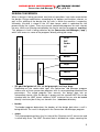
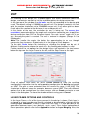
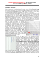
On selecting a DXF design file, a window opens that shows information about the
design, and contains controls to set the available options for design conversion.
In the top row of the window, the dxf units can be set according to the design grid
used. The default setting is 1000000 nm per dxf unit. For designs created in an inch
grid, the number should be set to 25400000 nm per unit. If any other grid has been
used, adjust the number to the distance in nm used per dxf unit.
In the center of the row, the resolution for arcs is being set. The arcres (arc
resolution) parameter defines the angle unit used when converting arcs to polylines
during conversion from DXF to Structure format. For each “arcres” angle unit in an
arc, one polyline point is created. The unit is entered in degrees (Range: 0.1 to
20 degrees)
Note: The smaller the angle, the better the approximation to an arc, though
conversion time increases. A good value is in the range of 3 to 9 degrees.
To the right, Scale factors for stretching or shrinking the design can be set. A
different scaling can be chosen for each axis. Any floating point number is valid.
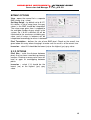
Further controls to set options for the design layers are located in the two frames
below the top row: the Layer Frame to the left, and the Step Frame to the right.
Layer Frame
Step Frame
Once all options have been set, press Create Default to store the resulting
configuration information into the corresponding configuration file dxf.cfg and create
an HIMT File with a name extracted from the source file name. If the HIMT File
should get a different name for example, because several HIMT Files with different
options are to be created from the same source, click on Create and enter a new
name in the dialog box. To close the window without saving, press Cancel.
LAYER FRAME OPTIONS AND CONTROLS
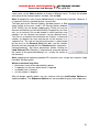
In the Layer Frame, a list of the layers present in the design is shown. Each layer is
assigned to a layer number and can be selected or deselected by clicking into the
leading Layer Checkbox. If there is more than one layer, it is also possible to set
operations between layers (<or> (default), <cut>, <xor>). For a further explanation of
these operations please refer to the Appendix section on Layer Merging. Also, the
18