1
User Manual for the
HEC-GV3-RTU Option Card
RTU/MODBUS Network
Communication
Option Board for use with Reliance
Electric GV3000 AC Drive
Third Edition,
20 July 1999
MAN0183-03
PREFACE
20 JULY 1999
PAGE 2
PREFACE
This manual explains how to use the RTU/MODBUS Network Communication Option Board for use with
Reliance Electric GV3000 AC Drive.
Copyright (C) 1999, Horner APG, LLC., 640 North Sherman Drive, Indianapolis Indiana, 46201. All rights
reserved. No part of this publication may be reproduced, transmitted, transcribed, stored in a retrieval
system, or translated into any language or computer language, in any form by any means, electronic,
mechanical, magnetic, optical, chemical, manual or otherwise, without the prior agreement and written
permission of Horner APG, LLC.
All software described in this document or media is also copyrighted material subject to the terms and
conditions of the Horner Software License Agreement.
Information in this document is subject to change without notice and does not represent a commitment on
the part of Horner APG, LLC.
PAGE 3
20 JULY 1999
PREFACE
LIMITED WARRANTY AND LIMITATION OF LIABILITY
Horner APG, LLC. ("HE") warrants to the original purchaser that the RTU/Modbus Network
Communication Option Board manufactured by HE is free from defects in material and workmanship
under normal use and service. The obligation of HE under this warranty shall be limited to the repair or
exchange of any part or parts which may prove defective under normal use and service within two (2)
years from the date of manufacture or eighteen (18) months from the date of installation by the original
purchaser whichever occurs first, such defect to be disclosed to the satisfaction of HE after examination
by HE of the allegedly defective part or parts. THIS WARRANTY IS EXPRESSLY IN LIEU OF ALL
OTHER WARRANTIES EXPRESSED OR IMPLIED INCLUDING THE WARRANTIES OF
MERCHANTABILITY AND FITNESS FOR USE AND OF ALL OTHER OBLIGATIONS OR LIABILITIES
AND HE NEITHER ASSUMES, NOR AUTHORIZES ANY OTHER PERSON TO ASSUME FOR HE, ANY
OTHER LIABILITY IN CONNECTION WITH THE SALE OF THIS RTU/MODBUS NETWORK
COMMUNICATION OPTION BOARD. THIS WARRANTY SHALL NOT APPLY TO THIS RTU/MODBUS
NETWORK COMMUNICATION OPTION BOARD OR ANY PART THEREOF WHICH HAS BEEN
SUBJECT TO ACCIDENT, NEGLIGENCE, ALTERATION, ABUSE, OR MISUSE. HE MAKES NO
WARRANTY WHATSOEVER IN RESPECT TO ACCESSORIES OR PARTS NOT SUPPLIED BY HE.
THE TERM "ORIGINAL PURCHASER", AS USED IN THIS WARRANTY, SHALL BE DEEMED TO
MEAN THAT PERSON FOR WHOM RTU/MODBUS NETWORK COMMUNICATION OPTION BOARD IS
ORIGINALLY INSTALLED. THIS WARRANTY SHALL APPLY ONLY WITHIN THE BOUNDARIES OF
THE CONTINENTAL UNITED STATES.
In no event, whether as a result of breach of contract, warranty, tort (including negligence) or otherwise,
shall HE or its suppliers be liable of any special, consequential, incidental or penal damages including,
but not limited to, loss of profit or revenues, loss of use of the products or any associated equipment,
damage to associated equipment, cost of capital, cost of substitute products, facilities, services or
replacement power, down time costs, or claims of original purchaser's customers for such damages.
To obtain warranty service, return the product to your distributor with a description of the
problem, proof of purchase, post paid, insured and in a suitable package.
ABOUT PROGRAMMING EXAMPLES
Any example programs and program segments in this manual or provided on accompanying diskettes are
included solely for illustrative purposes. Due to the many variables and requirements associated with any
particular installation, Horner APG cannot assume responsibility or liability for actual use based on the
examples and diagrams. It is the sole responsibility of the system designer utilizing the RTU/Modbus
NETWORK COMMUNICATION OPTION BOARD to appropriately design the end system, to
appropriately integrate the RTU/Modbus NETWORK COMMUNICATION OPTION BOARD Module and to
make safety provisions for the end equipment as is usual and customary in industrial applications as
defined in any codes or standards which apply.
Note: The programming examples shown in this manual are for illustrative
purposes only. Proper machine operation is the sole responsibility of the
system integrator.
PREFACE
20 JULY 1999
PAGE 4
Revisions to This Manual
This version (MAN0282-03) of the RTU/MODBUS Network Communication Option Board for use with
Reliance Electric GV3000 AC Drive User Manual contains the following revisions and additions:
a.
Added the Quick Termination Board (QTB) to Section 2.3. Starting with release C, the QTB is
included with the RTU/Modbus Option Card.
b.
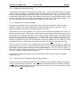
Revised the label on wire diagram in Figure 2.5.
c
Added Figure 2.6, which shows the Quick Termination Board.
d.
Added installation procedures for the Quick Termination Board in Section 2.3.
e.
Revised the timing response time from 100msec. to 350msec. in Sections 4.1.3, 4.1.4, 4.1.10,
and Table 4.1.
f.
Revised Section 4.1.10 to indicate that for fault reset command bit detection, it must be
maintained in both the 0 and 1 state for at least 20 milliseconds each.
g.
Revised Section A1.2.2, item 2 to indicate that the Start bit must make a low to high transition to
start the drive. Therefore, after power-up, the master must first send a Drive Control Word with
the Start bit reset.
PAGE 5
20 JULY 1999
PREFACE
PREFACE
20 JULY 1999
PAGE 6
TABLE OF CONTENTS
PREFACE ..........................................................................................................................................2
LIMITED WARRANTY AND LIMITATION OF LIABILITY .......................................................................3
ABOUT PROGRAMMING EXAMPLES ................................................................................................3
TABLE OF CONTENTS ......................................................................................................................6
SAFETY NOTICES .............................................................................................................................8
CHAPTER 1: INTRODUCTION ......................................................................................................... 10
1.1
Product Description ............................................................................................................. 10
1.2
Additional Information .......................................................................................................... 11
CHAPTE R 2: INSTALLATION ........................................................................................................... 12
2.1
Safety Notices ..................................................................................................................... 12
2.2
Installing the HEC-GV3-RTU Option Board ........................................................................... 12
2.3
Connecting the GV3000 Controller to an RTU Network .......................................................... 17
CHAPTER 3: CONFIGURATION ...................................................................................................... 20
3.1
Entering Network parameters ............................................................................................... 20
3.1.1
Network ID Assignment ................................................................................................. 20
3.1.2
Network Connection Type ............................................................................................. 20
3.1.3
Network Communications (Comm) Loss......................................................................... 21
3.1.4
Network Frame Assignment .......................................................................................... 22
3.2
ASCII Mode Support ............................................................................................................ 22
3.3
Connection Timeout Timer Adjustment ................................................................................. 23
3.4
Customizing the User-Configurable-Protocol-Frame (SMARTCFG)......................................... 23
CHAPTER 4: OPERATION AND FUNCTIONALITY ............................................................................ 26
4.1
Drive Data Registers Overview ............................................................................................. 26
4.1.1
General ........................................................................................................................ 26
4.1.2
Input Data Update Response......................................................................................... 26
4.1.3
Output Data Update Response ...................................................................................... 27
4.1.4
Limitation on Data Registers Accessible (Basic/Extended)............................................... 27
4.1.5
Input Data Transfer Conditions ...................................................................................... 27
4.1.6
Output Data Transfer Conditions .................................................................................... 28
4.1.7
Data Transfer Summary ................................................................................................ 28
4.1.8
Tune/Config Transfer Synchronization Flag .................................................................... 29
4.1.9
Parameter Processing Error Flag ................................................................................... 30
4.1.10 Data Retention Timing Requirements............................................................................. 30
4.1.11 Inaccessible Drive Parameters (Keypad Only parameters) .............................................. 30
4.1.12 Drive Ready Status Bit.................................................................................................. 31
4.2
Network Access to Drive Registers ....................................................................................... 31
4.3
Network Diagnostics............................................................................................................ 32
APPENDIX A: ACCESS TO DRIVE DATA REGISTERS .................................................................... 34
A1.1.
Drive Status ..................................................................................................................... 34
A1.2 Drive Control ....................................................................................................................... 34
A1.2.1 General ........................................................................................................................ 34
A1.2.2 Register 32: Drive Control Word ................................................................................... 35
A1.2.3 Register 33: Network Speed/torque Reference .............................................................. 35
APPENDIX B: DEFAULT TUNE/CONFIGURATION REGISTERS ....................................................... 36
PAGE 7
20 JULY 1999
PREFACE
PREFACE
20 JULY 1999
PAGE 8
SAFETY NOTICES
a.
DANGER
Only qualified electrical personnel familiar with the construction and operation of this equipment
and the hazards involved should install it. Read and understand this manual in its entirety before
proceeding. Failure to observe this precaution could result in severe bodily injury or loss of life.
b.
DANGER
The user is responsible for conforming to the NEC/CEC and all other applicable local codes.
Wiring practices, grounding, disconnects, and over-current protection are of particular
importance. Failure to observe this precaution could result in severe bodily injury or loss of life.
c.
DANGER
Do not install modification boards with power applied to the controller. Disconnect and lock out
incoming power before attempting such installation. Failure to observe this precaution could
result in severe bodily injury or loss of life.
PAGE 9
20 JULY 1999
PAGE INTENTIONALLY LEFT BLANK
INTRODUCTION
CH. 1: INTRODUCTION
20 JULY 1999
PAGE 10
CHAPTER 1: INTRODUCTION
1.1
Product Description
The Horner RTU/MODBUS Network Communications Option Board (HEC-GV3-RTU) allows a
GV3000 controller to be operated and monitored remotely via an RTU Master. The option board
mounts below the regulator board inside the GV3000 controller connected via a flexible ribbon
cable. Power for the option board comes from the GV3000 controller power supply.
The option board allows different levels of configuration and tuning of the GV3000 drive registers
according to preference and the capability of the RTU Network master. Once configured, the
drive can be completely controlled via the option board. Reset, fault code monitoring and
complete control can all be accomplished over an RTU network. In many applications, there may
be only a network interface connection, hard-wired emergency stop (Function Loss input), and
three-phase input and output power wiring.
Control and status information is passed between the drive and the network as 16-bit values
using RTU READ and PRESET Holding Register commands. Parameters are grouped in such a
manner to optimize control, tune and monitor packets. An RTU connection time-out timer may be
enabled to determine when RTU control is lost. If RTU control is lost, one of three different drive
operation responses can be selected. Commonly used RTU frame protocols (baud, stop bits
and data size mode) can be selected from a list or a user configurable frame protocol can be
created through the optional PC configuration utility SMARTCFG.
a.
Mechanical Description
The option board is a printed circuit assembly that mounts inside a GV3000 Controller. The
option board connects to the GV3000 Controller’s regulator board via a ribbon cable. A DB-15
connector is used to connect the option board to a dual twisted pair RS -422 network. An optional
RS-232-to-RS-422 converter can be used to provide an interface to an RS-232 serial connection.
The option board also contains 2 LEDs, which provide a visual indication of the state of the option
board, time-timer and communications activity.
b.
Electrical Description
The option board contains its own microprocessor. The microprocessor connects to one port of
the module’s dual port memory while the other port interfaces with the GV3000’s regulator. The
board contains a watchdog timer, which is enabled when power is turned on to the Controller.
The microprocessor must reset the watchdog timer within a specified period or the
microprocessor shuts down resulting in a “F 60” code on the GV3000 controller’s front-panel
display. The option board provides communications through a DB-15 RS-422 communications
port.
PAGE 11
1.2
20 JULY 1999
INTRODUCTION
Additional Information
The user needs to be familiar with all of the instruction manuals that describe the system
configuration. This can include, but is not limited to, the following:
D2-3323
GV3000 AC General Purpose (Volts/Hz) and Vector Duty Drive Software Startup
and Reference Manual Version 4.0 (or later).
D2-3324
GV3000 AC Power Modules Hardware Reference, Installation
Troubleshooting 1-150 HP @ 380-460 VAC Version 4.0 (or later).
and
CHAPTER 2: INSTALLATION
20 JULY 1999
PAGE 12
CHAPTER 2: INSTALLATION
2.1
Safety Notices
a. DANGER
Only qualified electrical personnel familiar with the construction and operation of this
equipment and the hazards involved should install it. Read and understand this manual in
its entirety before proceeding. Failure to observe this precaution could result in severe
bodily injury or loss of life.
b. DANGER
The user is responsible for conforming to the NEC/CEC and all other applicable local
codes. Wiring practices, grounding, disconnects, and overcurrent protection are of
particular importance. Failure to observe this precaution could result in severe bodily
injury or loss of life.
c.
DANGER
Do not install modification boards with power applied to the controller. Disconnect and
lock out incoming power before attempting such installation. Failure to observe this
precaution could result in severe bodily injury or loss of life.
2.2
Installing the HEC-GV3-RTU Option Board
Refer to Figures 2.1 – 2.4.
1.
2.
3.
4.
5.
6.
7.
8.
9.
Disconnect and lock-out all incoming power to the GV3000 controller.
Loosen the four (4) captive screws at the corners of the GV3000 controller cover and
remove the cover. Refer to Figure 2.2.
Disconnect the ribbon cable that runs between the right side of the regulator board and
the daughter board from the connector on the daughter board.
If the controller is equipped with a fan, disconnect the fan power leads from the connector
on the power board.
Remove the three (3) screws that fasten the stand-off bracket (to which the regulator
board and keypad are mounted) to the controller base, and remove the regulator
board/keypad/bracket assembly from the controller.
Invert the regulator board/keypad/bracket assembly so that the keypad is on the bottom.
The ribbon cable that connects to the daughter board extends from the left of the
regulator board, and the ribbon cable that connects to the RTU/Modbus Network
Communications Option Board extend from the right of the regulator board. Refer to
Figure 2.1.
Connect the ribbon cable that extends from the right side of the regulator board to the
connector on the RTU/Modbus Network Communication Option Board.
Mount the RTU/Modbus Network Communication Option Board to the underside of the
stand-off bracket. Use the two- (2) M3 self-tapping screws and lock washers (provided)
on the right side. Use the two (2) plastic rivets to fasten the left side of the board to the
stand-off bracket.
Re-install the regulator board/keypad/bracket assembly to the controller base.
PAGE 13
20 JULY 1999
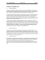
CH. 2 INSTALLATION
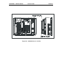
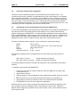
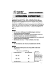
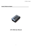
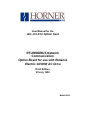
RIBBON CONNECTOR
TO REGULATOR BOARD
U4
U16
U15
J2
U17
U14
U10
U21
U18
U11
U3
U19
U9
U
8
U16
U22
U12
U1
U2
RS-485 Port
Figure 2.1 – RTU/Modbus Option Board
CHAPTER 2: INSTALLATION
20 JULY 1999
Figure 2.2 – GV3000 Drive (1-5 HP)
PAGE 14
PAGE 15
20 JULY 1999
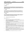
CH. 2 INSTALLATION
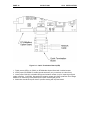
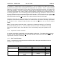
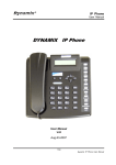
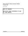
REGULATOR BOARD
9.5
9
8.5
8
7.5
7
1.5
1
.5
10
.5
"Y "
1
"X"
1 .5
2
2 .5
85
10
15
90
95
3
56919-100B
CON101
5
100
25
5
"Y"
TB 1
AI R
FLOW
A IR
FLOW
CON2
C O N7
ENTER
AUT O Fo rwa rd
RUNNING MAN
Re v e rs e
REMOT E
JOG
RUN
PRO GRAM JOG
AUTO
FO RWARD
REVERSE
PROGRAM
20
START
RPM
VOLTS
AMPS
Hz
Kw
T ORQUE
Passwor d
ST OP
RESET
16
1
10
"X "
0-56930-100A
DAUGHTER BOARD
NETWORK BOARD
805534-B
805534-A
Figure 2.3 – GV3000 Drive (7.5-10 HP)
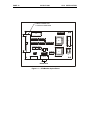
CHAPTER 2: INSTALLATION
20 JULY 1999
Figure 2.4 – GV3000 Drive (15 – 25 HP)
PAGE 16
PAGE 17
2.3
20 JULY 1999
CH. 2 INSTALLATION
Connecting the GV3000 Controller to an RTU Network
When connecting to the RTU/Modbus Communications Bus, the GV3000 drive should be wired
with the same cabling as other devices on the network. Refer to the EIA RS-422 standard for
cable and termination guidelines. The option board provides an internal 120 ohm terminating
resistor for the receive pair which can be strapped by shorting pins 9 and 10 on the DB-15
connector. Only the two end-point devices on the RS -422 cable should have terminators
enabled.
Starting with release C, included with the RTU/Modbus Option Card is a Quick Termination Board
(QTB) which is basically a DB-15 to Phoenix screw terminal converter. This QTB is provided to
reduce field installation time for 2-Wire networks by circumventing the need to solder DB15
connectors. The QTB also provides jumpers for enabling the internal termination resistor and
disabling the QTB ground isolation resistor (100 ohms). Refer to Figure 2.6 for installation.
Table 2.1 - DB-15 Port Pin-out (Female)
Pin
Tag
Direction
1
N/C
2
N/C
3
N/C
4
N/C
5
+5V
OUT
6
RTS OUT
7
GND
8
CTS IN
9
Terminator (short 9 & 10 to enable)
10
RXDIN
11
RXD+
IN
12
TXD OUT
13
TXD+
OUT
14
RTS+
OUT
15
CTS IN
*Handshake and factory lines are not used for RTU communications and should
not be connected.
*An optional RS -422 to RS-232 Adapter is available from Horner Electric. It
receives power from pins 5 (+) and 7 (C). The part number is HE693SNP232.
When using this adapter, the RS-232 pin-out is as follows:
Table 2.2 - DB-9 Port Pin-Out (Male)
Pin
Tag
Direction
1
N/C
2
TD
OUT
3
RD
IN
4
N/C
5
GND
6
N/C
7
CTS
OUT
8
RTS
IN
9
N/C
-
CHAPTER 2: INSTALLATION
20 JULY 1999
PAGE 18
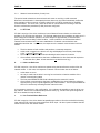
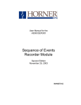
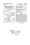
15-pin D-sub
TERM
RXDTXDRXD+
TXD+
0V
9
10
12
11
13
A(-)
B(+)
0V
7
A(-)
B(+)
0V
120 Ω
A(-)
B(+)
0V
Figure 2.5 – Two-Wire RS-485 Wiring Diagram
PAGE 19
20 JULY 1999
CH. 2 INSTALLATION
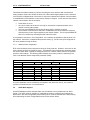
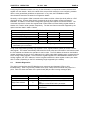
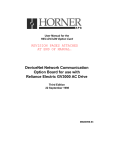
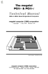
Figure 2.6 – Quick Termination Board (QTB)
1. Tightly secure QTB to J1 (DB15) on RTU/Modbus Option Board with included screws.
2. Insert jumper ‘EN TERM’ to enable internal terminator (only on devices on ends of bus).
3. Insert jumper ‘DIS ISO’ to disable QTB ground isolation resistor (only for improving marginal
quality networks). CAUTION: Bypassing the isolation resistor will reduce protection from voltage
difference on third wire ground (network) and option board digital ground.
4. Shield wire should be kept as short to prevent shorting with exposed metal.
CH. 3: CONFIGURATION
20 JULY 1999
PAGE 20
CHAPTER 3: CONFIGURATION
3.1
Entering Network parameters
This chapter covers configuration of the option board by entering the respective parameters
through the drive’s keypad. For instructions on operating the drive’s keypad, refer to the GV3000
Installation and Operation Instruction Manual (D2-3287).
The drive becomes active on the RTU network after the following steps are performed:
1.
2.
3.
4.
5.
6.
Connect the HEC-GV3-RTU option board to the RTU network through the RS-422 serial
connector.
Apply power to the drive.
Using the keypad, access the Network ID Assignment parameter (P.060) and assign a valid
RTU Id to the drive (limited to 1- 55).
Using the keypad, access the Network Connection Type parameter (P.061) and select either
Basic Drive Connection or Full Drive Connection.
Using the keypad, access the Comm Loss Selection parameter (P.062) and select the fault
action to be taken on a RTU connection time-out.
Using the keypad, access the Network Frame Assignment parameter (P.063) and select
either the User-configurable-protocol-frame (1) or one of the predefined protocol frames (2-8).
*Selecting the User-configurable-protocol-frame requires running an external
configuration program to set the specific parameters such as baud rate, parity, stop and
time-out.
**Note that P.061, P.062 and P.063 can also be accessed and changed via the network.
Serial communications can then be established with an RTU master. Input and Output
information can be accessed using the READ_HOLDING_REG and PRESET_HOLDING_REG
RTU commands. However, additional requirements must be met before inputs can be transferred
to the drive regulator. These requirements are described in Chapter 4.
3.1.1
Network ID Assignment
RTU communication networks can support up to 246 nodes on a network. However, because of
network hardware limitations, the number of nodes is generally limited to 32. Each node on an
RTU communications network must be assigned a unique ID number. This ID is used by the
RTU Master to route commands to the appropriate RTU device. The Network ID Assignment
parameter (P.060) contains the ID for this option board and can be any value from 1 to 55.
3.1.2
Network Connection Type
The drive’s Network Connection Type parameter defines the scope of status and control that the
RTU master has with the connected drive. Two types of data connections are provided: Basic
Drive Connection and Full Drive Connection. The Basic Drive Connection (0) limits the number of
control and status parameters accessible over the RTU network to the first 64 drive registers.
The Full Drive Connection (1) allows RTU access to all drive registers (see section 4.1.5 for
further limitations on writes). This selection becomes more prevalent when using the Tune/cnfg
enable bit to load configuration and tuning parameters from the RTU network. The drive’s
network connection type is selected with the Network Connection Type parameter (P.061).
PAGE 21
3.1.3
20 JULY 1999
CH. 3: CONFIURATION
Network Communications (Comm) Loss
The option board maintains a timeout timer that is reset on receiving a valid command.
Whenever communication is interrupted (the timer times out), the board immediately notifies the
drive regulator of this occurrence, and then waits for the next RTU command to re-establish
communications. The drive, then, reacts to the loss of communications according to how the
Comm Loss Selection parameter (P.062) has been configured.
a.
0 – IET Fault
If P.062 is equal to 0, the drive considers a Loss of Network Communication as a drive fault
resulting in an IET-type stop sequence. To eliminate extraneous fault conditions at power-up of a
drive configured for network operation, the drive delays for approximately 10 seconds after
power-up before annunciating a fault condition. A fault condition is annunciated thereafter if
network communications have not been established or if network communications was
established and then lost. In this case, the response to the network communication loss is as
follows:
•
•
•
•
b.
The drive latches a fault condition and performs a coast stop sequence.
A fault code is logged in the drive’s error log and displayed on the front-panel display
(“nCL” = network Comm Loss).
The front-panel REMOTE LED blinks indicating that the network is inactive.
Once network communications has been re-established, a drive fault reset is required to
re-start the drive. (Note: A fault reset does not clear the error log).
1 – Hold Last Reference
If P.062 is equal to 1, the drive continues to operate using the last reference received from the
network master. In this case, the response to network communication loss is as follows:
•
•
•
•
A fault does not occur.
An entry is made into the drive’s error log for each active to inactive transition of the
network communication status
The front-panel REMOTE LED blinks indicating that the network is inactive.
Once network communications has been re-established, the drive follows the reference
and sequencing control inputs supplied by the network master. The front -panel REMOTE
LED is on continuously indicating that the network is active.
It is important to note that, in this configuration, it is not always be possible to stop the drive over
the network. Some form of hardwired stop must be used (e.g., function loss input configured for
IET when asserted to stop the drive).
c.
2 – Use Terminal Block Reference
If P.062 is equal to 2, the drive obtains its speed/torque reference from the terminal block analog
input and its STOP input from the terminal block STOP input. All other inputs are held at the last
values received from the network master.
CH. 3: CONFIGURATION
20 JULY 1999
PAGE 22
This allows the network master to continue controlling the drive reference with a direct-wired
analog output to input and to STOP the drive with a direct-wired digital output to input. Note that
once the drive is stopped while in this mode, it cannot be re-started until network communications
is re-established or the operation control source (P.000) is changed. In this case, the response to
network communication loss is as follows:
•
•
•
•
A fault does not occur.
An entry is made into the drive’s error log for each active to inactive transition of the
network communication status.
The front-panel REMOTE LED blinks indication that the network is inactive.
Once network communications has been re-established, the drive follows the reference
and sequencing control inputs supplied by the network master. The front -panel REMOTE
LED is on continuously indicating that the network is active.
It is important to note that, in this configuration, it is not always be possible to stop the drive over
the network. Some form of hardwired stop must be used (e.g., function loss input configured for
IET when asserted to stop the drive).
3.1.4
Network Frame Assignment
RTU communications protocol supports a variety of frame protocols. However, each node on the
same network must be configured the same. The Network Frame Assignment parameter allows
the user to select either a typical pre-assigned protocol or create a custom protocol configuration
specific to their network. The following table indicates which frame protocol is selected by the
value in the Network Frame Assignment parameter (P063):
Selection
0
1
2
3
4
5
6
7
8
Mode
RTU
RTU
RTU
RTU
RTU
RTU
RTU
Table 3.1 – Network Frame Assignment
Baud
Parity
Stop bits
Connection timeout
(Run configurator only)
(User-configurable-protocol-frame)
9600
N
1
6 Sec
9600
O
1
6 Sec
9600
E
1
6 Sec
19.2K
N
1
3 Sec
19.2K
O
1
3 Sec
19.2K
E
1
3 Sec
57.6K
N
1
3 Sec
Since this parameter can be modified by the keypad or the network on-the-fly, use caution to
prevent non-intentional loss of communications.
3.2
ASCII Mode Support
Some RTU/Modbus masters transport data over the network in an encoded seven bit ASCII
format. This ASCII mode of operation is supported but must be configured by modifying the
Mode field in the User-configurable-protocol-frame (which must be selected as the active frame).
See Customizing the User-Configurable-Protocol-Frame section below.
PAGE 23
3.3
20 JULY 1999
CH. 3: CONFIURATION
Connection Timeout Timer Adjustment
This timer is used for determining when a Loss of Network Communications occurs. The
connection timeout timer is preset to a value determined by the current selection in the Network
Frame Assignment parameter. If this period is not acceptable, it can be changed by modifying
the Connection timeout field in the User-configurable-protocol-frame (which must be selected as
the active frame). The period should be set to a value larger than the expected time between
incoming RTU/Modbus commands. The timer can be disabled by setting the period to zero. See
Customizing the User-Configurable-Protocol-Frame section below.
3.4
Customizing the User-Configurable-Protocol-Frame (SMARTCFG)
If one of the preset Network Frame Assignment (P.063) selections don’t meet the requirements of
the network, the User-configurable-protocol-frame selection can be custom tailored with the
optional configuration tool SMARTCFG. An optional RS232-t o-RS485 converter (Horner Electric
APG m/n HE693SNP232) is also required to communicate with a PC com port. SMARTCFG is a
Horner Electric utility that is IBM compatible and only works with Dos version 3.3 or higher. The
SMARTCFG utility is used to configure stop bits, baud rates, data types and timeouts..
The User-configurable-protocol selection can be configured to support the following:
Modes:
Baud:
Parity:
Stop bits:
Connection time-out:
RTU or ASCII
1200, 2400, 4800, 9600, 14.4k, 19.2k, 38.4k and 57.6k
None, Odd and Even
1, 2
0 (off) – 120 sec.
The following combinations are not supported and can cause frame errors with some RTU
devices.
ASCII, None, 1 stop bit
- Actually transmits two stop bits
RTU, Odd or Even, 2 stop bits. - Actually only transmits one stop bit
The following steps are required to activate and program the User-configurable-protocol frame
selection:
a. Establish communication with SMARTCFG
1.
2.
3.
4.
5.
6.
Connect to a PC com port though the RS-232-to-RS-422 adapter to the option board
communications port.
Apply power to the drive
Using the keypad, access the Network Frame Assignment parameter (P.063) and set it to
0.
Remove power to the drive allowing the keypad indicators to go completely out.
Apply power to the drive and observe for the option card’s MS LED to flash RED.
Run SMARTCFG on the PC and configure the parameters.
Note that when the drive is power-cycled with the Network Frame Assignment parameter set to
zero, the option board is not capable of RTU communications or drive control. Setting the
Network Frame Assignment parameter to zero does not affect current communications until the
drive is power-cycled.
CH. 3: CONFIGURATION
20 JULY 1999
b. Set parameters with SMARTCFG
1.
2.
3.
4.
5.
Use arrow keys to select option (e.g. baud rate, stop bits, etc.)
Press the Enter key after selection is made
Press Space Bar key to change parameters of selection
After changing the parameters, Press the ESC key to return to main menu
Press ESC key once more to exit software utility
Figure 3.1 – Example Configuration Screen
Figure 3.2 – Example Configuration Screen
PAGE 24
PAGE 25
20 JULY 1999
CH. 3: CONFIURATION
c. Reset option card from Run-Configurator-only mode
1.
2.
Using the keypad, access the Network Frame Assignment parameter (P.063) and set it to
1 (User-Configurable-Protocol-Frame).
Once the MS LED begins to flash GREEN, the option board port is configured and ready
to control the drive.
CHAPTER 4: OPERATION
20 JULY 1999
PAGE 26
CHAPTER 4: OPERATION AND FUNCTIONALITY
4.1
Drive Data Registers Overview
4.1.1
General
The drive is monitored and controlled over the network by reading and writing through RTU/Modbus
commands to the drive’s data registers. The data registers are addressed over the network by a register
number (Reg #) and contain 16 bit values. The data registers are divided into separate types according
to function. Generally speaking, the Tune/Config registers hold an image of the P.xxx, H.xxx and U.xxx
parameters accessible by the drive’s keypad and the Control/Reference registers hold an image of the
drives physical inputs (start, stop, speed ref., etc). When the drive is configured for network control and
other certain conditions are met, the drive registers accessed by the network option card are selected as
an alternate source for controlling the drive as opposed to the keypad and/or physical input.
Network data written to the drive’s data registers is buffered before it is transferred to the drive’s internal
regulator. In order to minimize regulator board CPU loading, the rate of transfer of register data to the
drive regulator varies for different data register types. Additionally, some register data transfer are
blocked until additional conditions are met. The sections that follow describe each data type for input and
output register data along with the drive’s response and conditions for acceptance of transfer. The
presented response times do not include network transfer times.
The drive data registers which can be read or modified are listed in a table in Horner Electric’s
Supplement (SUP-0096). The table lists the register number, type, access and description for each
register.
4.1.2
Input Data Update Response
The drive’s input data is categorized as one of three types: control/reference, tunable or configurable.
Control/reference inputs include data which require fast update rates. This includes data such as
sequencing inputs (start, stop, run/jog, fwd/rev, etc.) and speed/torque reference. Control/reference
inputs are transferred from the data registers to the regulator every speed loop scan period (for the
GV3000, every 5 milliseconds), or as often as it is required by the drive. For example, if the drive is
configured to obtain its torque reference from the option port, it reads this data from the option port every
torque loop control scan.
Tunable inputs include parameters which modify the drive’s response regardless of the drive’s run state.
Tunable data includes parameters such as accel/decel rates, min/max limits, gains or offsets, etc.
Tunable inputs are transferred from the data register to the regulator whenever the regulator performs
the processing of new tunable parameters. This occurs approximately every 350 milliseconds while the
drive is running or stopped.
Configurable inputs include parameters, which alter the way that the drive operates in such a way that
they cannot be modified while the drive is running. Configuration data includes parameters such as
reference source selection, I/O configuration, motor/tach nameplate data, etc. Configurable inputs are
transferred from the data registers to the regulator whenever the regulator performs processing of new
configuration parameters. This occurs approximately every 350 milliseconds while the drive is stopped.
Values sent from the network master while the drive is running are not read in and used by the drive
regulator until the drive is stopped.
PAGE 27
4.1.3
20 JULY 1999
CHAPTER 4: OPERATION
Output Data Update Response
The drive output data is categorized as one of two types: runtime signal data or tunable- configurationand-status-data. Runtime signal data includes things such as selected speed reference value,
sequencing status (ready, running, etc.), drive fault flags, terminal block digital inputs state, and frontpanel display mode values (RPM, Volts, Amps). The information is transferred from the regulator to the
data registers every speed loop scan period (for the GV3000, every 5 milliseconds).
Tunable configuration and status data includes all other information provided by the drive which is not
defined as runtime signal data. This would typically include all drive parameter values. When accessed
via the network, the data provides a complete image of how the drive is configured and operating.
Tunable configuration and status data are transferred from the regulator to the data registers whenever
the regulator performs the processing of new tunable and configurable input parameters. This occurs
every 350 milliseconds.
4.1.4
Limitation on Data Registers Accessible (Basic/Extended)
The data registers are divided into a Basic and Extended set. The Basic set covers the first 64 data
registers while the Extended set includes the Basic set plus all remaining data registers. Drive parameter
“Network Connection Type” (P.061) selects the set and determines which data registers are updated or
read by the regulator. While configured to the Basic set, the drive blocks transfer (reading and writing) to
data registers above Register number 64.
Normally, networks are not used to access to data registers above register number 64. Therefore, this
option is especially useful in limiting the number of Tune/Config parameters which are modified in the
regulator when using the Tune/Config option described below. Since the network option board does not
provide default values for those Tune/Config data registers over register number 64, each Tune/Config
data register above that number must be initialized over the network when using the Extended set and
the Tune/Config option.
Note: Use care not to inadvertently set Reg. 61 since this register (P.061) enables the Extended set.
4.1.5
Input Data Transfer Conditions
The network option board must be actively communicating with a master, and it must be selected as the
drive’s control source (P.000 = OP(2)) in order for any inputs to be transferred from the data registers
to the drive regulator. Note that the keypad can still be used to change parameter values when the drive
control source is the network option. However, any changes made via the keypad are overwritten with
data register values when the next input data update occurs. This needs to be kept in mind if parameter
changes need to be made while the network option is the control source for the drive.
In addition, a network -controlled “Tune/Cnfg input enable” bit (Drive Control Word: Reg 32, bit 14) is
provided to enable the transfer of tunable and configurable register data to the drive regulator. Until this
bit is set ON (1), only Control/Reference data registers are read in by the drive regulator. This
gives the master's application program direct control over when tunable and configurable parameter
values are read in by the drive, if at all.
CHAPTER 4: OPERATION
20 JULY 1999
PAGE 28
For example, if a master loads Tune/Config parameters, it must first initialize the tunable and configurable
parameter data through network messages to the appropriate data registers. Then, a network message
setting the “Tune/Cnfg input enable” bit in the Drive Control Word enables the transfer of this data to the
drive’s data registers. Once the Tune/Config register data is transferred to the drive’s regulator, the
“Tune/Cnfg input enable” bit must be reset to prevent regulator overhead and un-expected changes in
Tune/Config parameters. The “Tune/Config Update synchronization flag” described in Section 4.1.8 can
be used to determine when the regulator has transferred the data. Those Tune/Config data registers not
explicitly preloaded through network messages contain default values as described in the Appendix B.
Note that the default value is not the same as the value previously loaded by the keypad.
Alternately, should the user prefer that inputs are set exclusively by the keypad and that the network only
modifies the control/reference data to the drive, the master should not set the “Tune/Cnfg input enable”
bit. The drive is, then, configured locally, but start, stop, reset and reference are sent from the network
master.
Note: The user needs to exercise caution to prevent the unintentional setting of the Tune/Cnfg
input enable bit (Reg 32, bit 14). This could cause the drive to transfer un-initialized tune/config
data from the network option card to the drive, which could radically change the operation of the
drive.
4.1.6
Output Data Transfer Conditions
All regulator output data is transferred to the data registers continuously. The network does not have to
be active, and the network option does not have to be selected as the drive control source (P.000). No
output enable control bit is necessary.
4.1.7
Data Transfer Summary
Table 4.1 summarizes the response times to the different drive data types described earlier in this
Sections 4.1.2, 4.1.3, and 4.1.6.
Table 4.1 – Transfer between Data Registers and the Drive Regulator
Direction
Category
Conditions
Input (to drive)
Control / Reference
drive running or stopped
Tunable
drive running or stopped
Configurable
Drive stopped
Output (from drive)
Runtime
Always
Tunable, Configuration &
Always
Status
Rate
5ms
350ms
350ms
5ms
350ms
PAGE 29
20 JULY 1999
CHAPTER 4: OPERATION
Figure 4.1 summarizes the conditions which effect transfer of input and output register data to the drive’s
regulator.
Figure 4.1 - Transfer Condition Logic Summary
4.1.8
Tune/Config Transfer Synchronization Flag
To allow the network master's application program to determine when tunable and configurable inputs
have been updated in the drive, a sync write bit (Drive Control Word: Reg. 32, bit 15) is provided which is
copied to a sync read bit (Status Word: Reg. 0, bit 7) by the drive. The drive copies the sync write bit to
the sync read bit after the drive has read in and processed all tunable and/or configurable input registers.
The “Tune/Cnfg input enable” bit must be set (1) in order for this to happen. Note that configurable type
inputs are only read in by the drive while it is not running. This does not affect the copying of the sync bit
since tunable inputs are still transferred.
By toggling the sync bit in the master and by monitoring the copied value from the drive, the master's
application program determines when the drive has read in data. This feature is provided for those
applications which can require this type of synchronization. It is not necessary for the master's
application program to use it as it has no affect on drive operation.
To determine when changes to tunable and configurable data on the drive have been completed, the
master performs the following sequence:
1.
2.
3.
4.
Modify the tunable and/or configurable register data in the appropriate network register(s).
Set the Tune/Cnfg input enable flag (if not already set).
Toggle the network synchronization flag.
Monitor the loopbacked copy (read register) of the network synchronization flag until it equals the
value written in step 3.
CHAPTER 4: OPERATION
4.1.9
20 JULY 1999
PAGE 30
Parameter Processing Error Flag
A “Parameter Processing Error Flag” (Fault Log Entries: Reg. 14, bit 8) is provided to allow the network
master to determine whether any parameter values are unacceptable to the drive. If this flag is set (1),
then one or more data register values transferred to the drive were rejected. If this flag is not set (0), then
all data register values sent to the drive were accepted. Note that the “tune/config inputs enable” bit must
be set (1) before the drive can read-in, and consequently process, any Tune/Config parameters. The
parameter processing error flag is updated approximately every 100 milliseconds.
4.1.10 Data Retention Timing Requirements
All tunable and configurable drive input register values must be maintained by the network master's
application program for at least 350 milliseconds to assure that they are seen by the drive. This is
particularly relevant for data which is transition-detected by the drive.
Control/reference data types generally do not have this 350 millisecond requirement since they are
scanned by the drive every 5 milliseconds. Special cases to this rule are the start input and the error log
clear command. The start input requires a 0 to 1 transition in order to start the drive. The start input from
the network can be delayed by the drive for up to 100 milliseconds. This is done to synchronize a drive
start to the processing of new confi gurable data. In order for the network master to assure this 0 to 1
transition is detected by the drive, the network master must maintain both the 0 and 1 states for at least
100 milliseconds each. Values, which are maintained for less time may not be detected by the drive.
The error log clear command bit is processed every 350 milliseconds even though it is defined as
control/reference data. A 0 to 1 transition must be detected by the drive after the network is active and
the control source has been se lected to be the network option for the error log to be cleared. In
order for the network master to assure this 0 to 1 transition is detected by the drive, it must maintain both
the 0 and 1 states for at least 350 milliseconds each.
For fault reset command bit detection, it must be maintained in both the 0 and 1 state for at least 20
milliseconds each.
4.1.11 Inaccessible Drive Parameters (Keypad Only parameters)
There are a few GV3000 parameters which are not accessible through drive data registers, and therefore,
are not accessible through the network. Table 4.2 is a list of parameters that are inaccessible. Because
most of the inaccessible parameters are related to local drive control functions only, the inability to access
the parameters do not limit network control.
PAGE 31
20 JULY 1999
CHAPTER 4: OPERATION
Table 4.2 – Inaccessible Parameters
Description
Parameter
Second menu enable password
P.006
Terminal block digital inputs config
P.007
Terminal block speed reference selection
P.008
Second accel rate
P.017
Second decel rate
P.018
MOP acc/dec rate
P.023
MOP reset configuration
P.024
Multispeed preset 1
P.031
Multispeed preset 2
P.032
Multispeed preset 3
P.033
Multispeed preset 4
P.034
Multispeed preset 5
P.035
Multispeed preset 6
P.036
Multispeed preset 7
P.037
Multispeed preset 8
P.038
Restore parameters defaults command
P.050
Program disable password
P.051
Network drop number
P.060
Vector torque loop self tune enable
U.008
4.1.12 Drive Ready Status Bit
The Drive Ready status bit (Drop_1, Reg 0 Bit 0) is used to indicate that a 0 to 1 transition on the start
input starts the drive. The Drive Ready bit is ON (1) when all of the following conditions are met, and OFF
()) when one or more are not met:
• No drive faults are active (Drop_1 Reg 0 Bit 2 = 1)
• Stop input is ON (1) (Drop_1 Reg 32 Bit 1 = 1)
• Front -panel STOP/RESET button is not pressed
• Function loss TB input closed (Drop_1 Reg 0 Bit 12 = 1)
• A download from the serial port (using the CE3000) is not in progress
If in the JOG mode (Drop_1 Reg 0 Bit 3 = 1), then in addition, the vector torque loop self-tune enable
parameter must be OFF (U.008 = OFF).
4.2
Network Access to Drive Registers
The drive registers accessible over the network are summarized in SUP0096 - Supplement for
Reliance GV3000 Drive Registers, which is provided as part of this document. Based on the information
provided in this supplement and section 4.1, the user must decide which of these drive registers to
access over the network.
Note: that when the drive Network Connection Type (parameter P.061) is configured for Basic Drive
Connection, ONLY the first 64 drive registers contain valid data.
Note: Always verify that ALL tune/config parameters in the current Drive-Connection- set have been
initialized to a sane value before writing the Tune/Config-inputs- enabled bit in the first drive command
register.
CHAPTER 4: OPERATION
20 JULY 1999
PAGE 32
Configuring RTU/Modbus masters can vary in what information is required to access a selected drive
register over the network. While it is outside of the scope of this manual to cover configuring a master
device, some generalized guidelines are presented. In any case, the RTU/Modbus master
documentation should be consulted for configuration details.
Generally, a drive register’s offset is entered at the master as either a frame (low level) offset or a PLC
(high level) offset. A frame offset directly corresponds to the drive register number presented in
SUP0096. In addition, a frame offset configuration generally also requires a command number. The
commands required to access drive register data is either Read or Preset Holding register based on
whether it is a read or write operation respectively. The low level frame commands supported by the
option board are listed in table 4.3 below.
Table 4.3- RTU/Modbus Function Codes
Function
Code
Valid Offsets
Maximum Length
Read (Holding) Registers
3
0-182
183
Preset Single (Holding) Register
6
0-182*
1
Preset Multiple (Holding) Registers
16
0-182*
183
Read Exception Status
7
Loopback Maintenance
8
(sub commands: 0,1,4,10-15)
*Every other 32 word region starting at offset 0 is read only and generates an error if
addressed by this command.
A high level configuration generally only requires a “PLC” register address (offset) to access a drive’s
data register. The master automatically determines the frame offset and commands to use based on both
the PLC address and whether the operation is read or write. The PLC address is based on the Modbus
register addressing scheme in which addresses in the 4001-4999 (40001-49999) range correspond to the
PLC’s analog holding registers. Since the drive’s registers appear to the RTU/Modbus network as PLC
holding registers, the “PLC” address of a drive’s register would be the drive register number ‘plus’ either
4001 or 40001 (depending on the PLC addressing range supported by the master)
4.3
Network Diagnostics
The option board provides both RTU/Modbus error responses and diagnostic LEDs to aid in
troubleshooting. Table 4.4 gives the possible errors (error codes) which the master may return for a
point. Table 4.5 shows the status of the option board (MS) and the incoming messages (NS).
Error
Invalid Function Code
Illegal Data Address
Illegal Data Value
Table 4.4 – RTU/Modbus Response Errors
Code
Reason
1
Requested RTU function code not supported
Attempt to access parameter beyond valid offset
2
(or)
Attempt to write READ-ONLY parameter.
3
Attempt to read or write more than 125
parameters.
PAGE 33
MS Led
Red (Solid)
Red (Flash)
Green (Solid)
Green (Flash)
NS Led
Red (Flash)
Yellow (Flash)
Green (Flash)
20 JULY 1999
CHAPTER 4: OPERATION
Table 4.5 – Option Board LEDs
Description
Factory Diagnostics mode (Contact Technical Support)
User-configurable-protocol-frame program mode
Network active
Network not active (connection time-out timer expired)
Description
Data activity but invalid frame protocol or RTU/checksum error
Valid RTU frame with non-match address (normal if other RTU
devices communicating )
Valid RTU frame addressed to this device.
APPENDIX A
20 JULY 1999
PAGE 34
APPENDIX A: ACCESS TO DRIVE DATA REGISTERS
A1.1.
Drive Status
The remote run-time status of the drive is typically returned in Drive Registers 0 through 11. These
values reflect the drives actual status regardless of the Control Source or the Auto/Remote mode. Refer
to Horner Electric’s Supplement (SUP-0096), Table1 (description column) to determine the Drive Register
functions. Registers 0, 1 and 5 are covered in more detail in this appendix.
a.
Register 0: Status Word
The first half of the word provides a bit-mapped run-time status of the drive similar to that which is
displayed by the keypad. The second half of the word provides an indication of the physical inputs to the
Control Terminal.
The "drive ready" status bit (Status Word: Reg. 0, bit 0) is used to indicate that a 0 to 1 transition on the
start input starts the drive. The drive ready status bit is ON (1) when all of the following conditions are
met and OFF (0) when one or more conditions are not met:.
•
•
•
•
No drive faults are active (Fault Active: Register 0, bit 2)
Stop input is ON (1) (!Stop: Register 32, bit 1)
Front -panel STOP/RESET button is not pressed
Function loss TB input closed (monitored w/Function Loss: Register 0, bit 12)
b.
Register 1: Selected Speed Reference
This register returns the currently selected speed reference. This value is scaled from 0 - 4095 where
4095 is the maximum allowable value. (i.e. The maximum 4095 value may correspond to 10 Volts at the
Control Terminal: Analog Speed Reference Input or the maximum value placed in Register 33).
c.
Register 5: RPM Display
This value returns the current output frequency (scaled) of the motor. The value returned is scaled
according to those formulas presented in the GV3000/SE AC General Purpose (Volts/Hz) and Vector
Duty Drive Software Startup and Reference Manual under Speed Display Scaling (P.028).
A1.2
Drive Control
A1.2.1 General
Network run-time drive control consists primarily of manipulating Drive Registers 32, 33, and sometimes,
34. Once in OPtion mode, these parameters is used to control the drive alternately to those values input
through the Control Terminal and/or Keypad when the drive is in LOCaL or rEmote mode.
PAGE 35
20 JULY 1999
APPENDIX A
A1.2.2 Register 32: Drive Control Word
The bits in this register are used by the drive alternately to the Discrete voltage inputs to the Control
Terminal. Generally, asserting a bit in the Drive Control Word while under OPtion mode performs the
same function as asserting a control voltage on the Control Terminal while under reMote mode.
Exception and special conditions are listed as follows:
1.
2.
3.
Before the drive can be started with the Start bit, the conditions which activate the Drive Ready bit
into the Status Word (Register 0) must be active.
Start bit must make a low to high transition to start the drive. Therefore, after power-up, the master
must first send a Drive Control Word with the Start bit reset. Once Drive Status indicates the drive
started, the Start bit can be reset. The drive is then stopped by releasing the Stop bit .
Tune/Cnfg input enable bit causes the drive to accept option card default (or updated) Tune/Config
parameters. Setting this bit can severely alter drive operation (See Chapter 4).
A1.2.3 Register 33: Network Speed/torque Reference
This register is used to control the drive’s speed reference when the drive is in Option mode, and the
Remote/Local control is in Remote mode. This value is scaled such that the 0 is equal to stop, and the
value 4095 is equal to full speed.
PAGE 36
20 JULY 1999
APPENDIX B
APPENDIX B: DEFAULT TUNE/CONFIGURATION REGISTERS
TheTune/Config data registers not explicitly preloaded through Explicit network messages contain default
values as described in Table B1.
Table B1- Default Tuning/Configuration
Register Preload Values
Register
Default Load Value
32
Stop
33
0
34
0
35
0
36
0
37
20.0
38
20.0
39
5.0
40
60.0
41
100
42
0
43
1.000
44
0
45
0
46
0
47
0
48
0
49
5.0
50
0
51
0
52
1800
53
0
54
0
55
0
56
0
57
0
58
0
59
0
60
0
61
0
62
0
63
P.063
PAGE 37
20 JULY 1999
NOTES
APPENDIX B