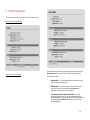
1
1. Introduction
Congratulations on your purchase of Solectek’s SKYWAY 5000 Series
Bridge/Router, a feature rich, best-in-class wireless solution. This User’s Guide
will describe the operation of your SKYWAY 5000 unit in detail.
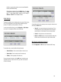
SYSTEM FEATURES
•
•
•
•
•
•
•
•
Field proven OFDM modulation allowing near line-of-sight deployment
and strong immunity to multi-path.
Data rates from 6 Mbps to 72 Mbps.
High power radio (400mW) and improved radio sensitivity for best in
class link ranges – over 10 miles with only 1-foot panel antenna.
Power over Ethernet (PoE) for simplified cable routing – only a single
outdoor CAT5 cable is needed.
Integrated antenna/radio simplifies installation and eliminates lossy RF
coax runs.
AES encryption for the ultimate in security and data protection.
Client access control via MAC address filtering.
Intuitive Web based user interface.
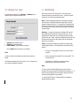
PACKAGE C ONTENTS
•
•
•
•
•
(2)
(2)
(2)
(2)
(2)
•
•
•
CD-ROM containing documentation and software utilities.
Registration Card.
Warranty and Compliance Card.
SKYWAY point-to-point radios: 5101, 5301 or 5501.
24VDC Power Supplies.
Power over Ethernet (PoE) injectors.
Two-axis mast mounting kits.
Ethernet cable weatherproofing glands.
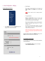
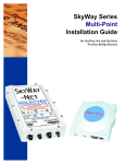
SKYWAY 5000 Series
Point-to-Point
User’s Guide
For SkyWay 5101, 5301 and 5501
NOTE: CAT5 Ethernet cable is not included in the package. Please contact
Solectek for information on available UV -protected Ethernet cables for outdoor
use.
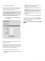
System Requirements
•
•
Indoor CAT 5 cable – straight cable if connecting to a hub/switch,
cross-over cable if connecting to a PC.
A computer running TCP/IP over Ethernet for testing of the client in a
live multipoint wireless network.
1
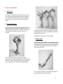
2. Physical Installation
A. INTRODUCTION
Your SkyWay radio is designed to be mast mounted on a rooftop or radio
tower. After determining the best location for your radio, installation can
begin. (Please refer to Solectek’s RF Site Design Guide on the included
documentation CD for more information about choosing an ideal radio
location.)
B. MOUNTING KIT ASSEMBLY
A two-axis mounting kit is included with each SkyWay radio allowing secure,
adjustable mounting to a pole or mast. The mounting kit must first be
assembled and then attached to the back of the SkyWay radio. Please refer
to the printed directions included in the mounting kit box for more
information.
The mounting kit attaches to the back of the SkyWay radio by way of four
self-tapping screws. Be sure screws are perpendicular to the radio back
before driving the screws inward.
Wrench tighten all screws/nuts prior to outdoor installation.
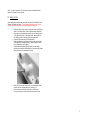
C. ETHERNET C ABLE
Only a single, outdoor rated, Cat5 Ethernet cable is needed to connect the
Skyway radio to the indoor PoE Injector. To ensure all-weather operation,
the included weatherproofing cable gland must be built onto the Ethernet
cable. This seal can be slipped onto the Cat5 cable before attaching the
RJ45 connectors at the end(s).
There are three possible methods in arranging the clamp pieces to
accommodate small, medium and large mast diameters. Please refer to the
figure on the next page. Note that the middle and rightmost images differ
only in the length of bolt used to fasten the two clamp pieces together.
Note: the total combined length of the two Ethernet cables between the
radio and hub/switch/PC must not exceed 300 feet.
2
Note: In order to maintain FCC compliance, use of a shielded Ethernet
cable with Skyway 5000 is required.
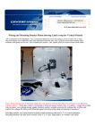
D. INSTALLATION
After locating and installing the radio mast, the physical installation of your
Skyway 5000 radio can begin. If benchtesting the system first, you may
want to skip this step and return to it after testing is completed.
1.
2.
3.
4.
5.
6.
7.
8.
Using the clamp on the mast mounting kit, attach the SkyWay
radio to the chosen mast. Wrench tighten mast clamp bolts.
Using the two axis adjustment pivots, point the radio antenna
in the general direction of the target radio. Partially tighten
axis bolts so that fine-tuning can be performed later.
Connect RJ45 connector to the SkyWay radio.
Slide cable gland up the Ethernet cable to radio housing and
screw gland into threaded opening. Wrench tighten, but do
not overtighten the nylon gland.
At opposite end of gland (pointing away from the radio),
tighten seal nut against Ethernet cable. Wrench tighten, again
being careful not to overtorque the gland.
Place PoE Injector and Power Supply in a convenient, indoor
location near to the destination hub, switch or PC.
Route and connect outdoor Cat5 cable to PoE Injector.
You may now plug in the Power Supply to power the unit.
3
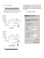
3. System Configuration
A. C ONNECTING THE SKYWAY UNIT FOR C ONFIGURATION
Using the appropriate diagram below as a guide, cable together your
SkyWay test system. Connect your PC to the POE injector using (a)
crossover Ethernet cable or (b) straight cable and a hub/switch.
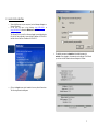
B. SET
UP
YOUR COMPUTER’S TCP/IP
Open networking properties in your Windows OS. Find the TCP/IP setup window
of your wired Ethernet adapter. The details on how to set the IP address of
your computer’s Ethernet adapter are different, depending on Windows versions
(95/95/2000/Me/XP). Please consult your Windows OS documentation. Shown
below is the Windows 2000 TCP/IP Properties window. Set the IP addresses to
the following values.
Ethernet’s IP Address:
Subnet Mask:
192.168.0.100
255.255.255.0
PROPERTIES
4
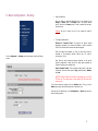
C. LOG-IN
•
•
TO YOUR
SKYWAY
Start a Web Browser on your computer (such as Netscape Navigator or
Microsoft Explorer).
At the URL line, type in the following: http://192.168.0.1 or
http://192.168.0.2 to access the Welcome screen below.
The Skyway 5000 Point-to-Point kits are shipped in preconfigured pairs.
One unit will be configured to have a default IP address of 192.168.0.1
and the other will have an IP address of 192.168.0.2.
•
•
The default username is solectek and the default password is
solectek. Once logged in, the password can be changed. Click OK and
you will see the Main Status screen and Navigation Toolbar:
Click on the login menu option located in the navy-blue left menu bar.
The following screen should appear:
5
4. Basic Configuration - Bridging
•
C HOOSING BRIDGING OR ROUTING
Mode of Operation
The user needs to determine whether the unit will operate in the
Bridge or Router mode. The Bridge mode is the system default
option.
Warning: Be sure to reboot the unit if you change the mode of
operation.
•
Throughput Optimization
Distance to Farthest Client: The system can adjust internal
parameters according to the chosen link distance in order to optimize
the RF link conditions and maximize the data throughput.
Enter the longest link distance (in miles) to client units, known or
expected, in the multipoint network. Options are 1-27 miles in
increments of 1 mile.
•
Note that the actual maximum distance depends on the specific
network configuration. Please check the range guide available on
Solectek’s web site, www.solectek.com
Click the System menu option under the Advanced category on the
Navigator Toolbar to access the following screen:
NOTE: This Output Transmit Power feature is available only on the 5101
PTP Kits only. The higher-power, longer-distance PTP kits have fixed
output power.
If you have made any changes, click the Update button. Then, go to the
Reboot menu option and follow instructions to restart the unit.
IP and Wireless Configuration
Go to the Configuration – Basic menu option as seen in the above navigation bar
to see the following screen:
•
Click the Configuration -> Basic menu option on the Navigator
Toolbar to access the following screen:
6
Radio Spectrum Bandwidth: Two choices are available - Normal
(default setting) and Wideband. In the Normal mode, each channel
occupies 20 MHz of radio spectrum. In the wideband mode, each channel
occupies 40 MHz of spectrum.
If a radio is likely to be installed in an area with other 5.8 GHz radios
nearby, it is best to use the Normal bandwidth setting as this allows for
more non-overlapping channels. This is also the case if multiple radios are
to be co-located on a single tower or rooftop.
If maximizing throughput and distance is of primary importance, then it
may be best to use a Wideband bandwidth. At any given datarate (e.g. –
36 Mbps), the Wideband setting will attain a longer link distance as
compared to the Normal setting. The Wideband setting also allows for
higher data rate settings not available on the Normal setting.
After changing the Radio Spectrum bandwidth value, be sure to click the
Select button below.
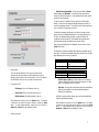
The following is the table for available radio frequencies and data rates for
each option. (Note that the allowable frequencies may differ from the table
below depending on the country of operation)
NORMAL (20MHz)
Frequency (MHz)
Data Rate (Mbps)
•
System name
This is an optional description of the unit for convenience that
eliminates the need to remember the MAC address when trying to
identify a particular radio in the wireless network. This is not related to
the identification of the unit on your wired local area network.
•
IP Address: This is the IP address of the unit.
-
Subnet Mask: This is the subnet mask of the unit.
-
Default Gateway: the default gateway of the unit.
After changes are complete, click on the Update button. If a mistake
is made, you can restore the previous setting by clicking the Reset
button. To make changes effective, reboot the unit by clicking on
Advanced -> Reboot from the Navigation Toolbar.
•
WIDEBA ND (40MHz)
Frequency (MHz)
5745, 5785, 5825
Data Rate (Mbps)
72, 48, 36, 24, 12
-
Radio Frequency (MHz): the center frequency of the selected
frequency channel. In the Normal mode, each channel is 20 MHz
wide. In the wideband mode, it is 40 MHz.
-
Data Ra te: air transmission/receive data rates. Note that different
data rates are available for normal and wideband modes, as
detailed in the table above.
IP properties (LAN)
-
5735, 5755, 5775, 5795, 5815,
5845
36, 24, 18, 12, 6
All radios on a given wireless network must use the same Bandwidth,
Frequency and Data Rate setting.
After changes are complete, click on the Update button. If a mistake
is made, you can restore the previous setting by clicking the Reset
button. To make changes effective, reboot the unit by clicking on
Advanced -> Reboot from the Navigation Toolbar.
Wireless properties
7
5. Basic Configuration - Routing
•
Mode of Operation
The user needs to determine whether the unit will operate in the
Bridge or Router mode. The Bridge mode is the system default
option. Switch to the Router option in order to activate the unit as a
wireless router.
Warning: Be sure to reboot the unit if you change the mode of
operation.
•
Throughput Optimization
Distance to Farthest Client: The system can adjust internal
parameters according to the chosen link distance in order to optimize
the RF link conditions and maximize the data throughput.
Go to the Advanced –> System menu option above to see the following
screen:
Enter the longest link distance (in miles) to client units, known or
expected, in the multipoint network. Options are 1-27 miles in
increments of 1 mile.
Note that the actual maximum distance depends on the specific
network configuration. Please check the range guide available on
Solectek’s web site, www.solectek.com
Output Transmit Power: This controls the output power of the radio
transmitter. There are three options: High (system default), Medium,
and Low
NOTE: This Output Transmit Power feature is available only on the 5101
PTP Kits only. The higher-power, longer-distance PTP kits have fixed
output power.
If you have made any changes, click the Update button. Then, go to the
Reboot menu option and follow instructions to restart the unit.
Once the unit has rebooted, go to the Configuration –> Basic menu option to
see the following screen:
8
IP Address – Enter the IP address of the Ethernet port.
Subnet Mask – Enter the correct Subnet Mask of the Ethernet port
•
Default Gateway
Enter the correct gateway IP address
•
Wireless properties
Radio Spectrum Bandwidth: Two choices are available - Normal
(default setting) and Wideband. In the Normal mode, each channel
occupies 20 MHz of radio spectrum. In the wideband mode, each channel
occupies 40 MHz of spectrum.
If a radio is likely to be installed in an area with other 5.8 GHz radios
nearby, it is best to use the Normal bandwidth setting as this allows for
more non-overlapping channels. This is also the case if multiple radios are
to be co-located on a single tower or rooftop.
If maximizing throughput and distance is of primary importance, then it
may be best to use a Wideband bandwidth. At any given datarate (e.g. –
36 Mbps), the Wideband setting will attain a longer link distance as
compared to the Normal setting. The Wideband setting also allows for
higher data rate settings not available on the Normal setting.
After changing the Radio Spectrum bandwidth value, be sure to click the
Select button below.
The following is the table for available radio frequencies and data rates for
each option. (Note that the allowable frequencies may differ from the table
below depending on the country of operation)
•
System name
This is an optional description of the unit for convenience that
eliminates the need to remember the MAC address when trying to
identify a particular radio in the wireless network. This is not related to
the identification of the unit on your wired local area network.
Note that, unlike the Bridge mode, there is a separate IP address for the
Ethernet and RF port. Both ports must be configured with a valid IP address in
order to use the routing correctly.
•
Data Rate (Mbps)
5735, 5755, 5775, 5795, 5815,
5845
36, 24, 18, 12, 6
WIDEBAND (40MHz)
Frequency (MHz)
5745, 5785, 5825
Data Rate (Mbps)
72, 48, 36, 24, 12
-
Radio Frequency (MHz): the center frequency of the selected
frequency channel. In the Normal mode, each channel is 20 MHz
wide. In the wideband mode, it is 40 MHz.
-
Data Rate : air transmission/receive data rates. Note that different
data rates are available for normal and wideband modes, as
detailed in the table above.
Ethernet Port
IP Address – Enter the IP address of the Ethernet port.
Subnet Mask – Enter the correct Subnet Mask of the Ethernet port
•
NORMAL (20MHz)
Frequency (MHz)
RF Port
9
All radios on a given wireless network must use the same Bandwidth,
Frequency and Data Rate setting.
After changes are complete, click on the Update button. If a mistake
is made, you can restore the previous setting by clicking the Reset
button. To make changes effective, reboot the unit by clicking on
Advanced -> Reboot from the Navigation Toolbar.
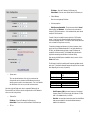
Static Routing
There are two possible choices in configuring the unit as a router: Static routing
or RIP. The choice depends on your overall network consideration and your
preference. For details, consult any textbook on IP routing.
In order to activate Static Routing, go to the Configuration – Static Routes
menu option in the navigation toolbar to see the screen below
You can delete a static route by checking the box to the right of the static route
and clicking the Delete button.
•
Check All – You can check all boxes by clicking this button. This is
usually used when you want to delete all static routes. Be careful in
using this button, as it could erase all of your routing information.
•
Clear All – Clicking this button will uncheck all boxes.
•
Delete - Both Delete buttons on the screen achieve the same result:
delete all route entries with boxes to the right of entries checked.
RIP (Router Information Protocol)
Go to the Configuration –> RIP menu option to activate the RIP routing
For each static route, you need to add the following information
•
Network Address – Enter the network address of the static route.
•
Network Mask – Enter the network mask of the static route.
•
Getaway – Enter the gateway of the static route.
Once you have typed in the above, click the Add button to include the newly
typed static route to your static route list. Then, your static route screen will
look like the following:
10
Using Multicast, unnecessary replication of data packets is reduced to conserve
bandwidth.
•
Disable/Enable: The pull-down choices either enable or
disable multicast option
Update Interval
By default, every 30 seconds the SkyWay 5000 router will advertise its
routes to other RIP v.II devices. This value can be changed, but it
must remain a multiple of the value for EXPIRE TIME.
•
Expire Time
By default, 180 seconds will pass after the last route update has
occurred and the SkyWay 5000 will remove its route table entry.
The following describes port configuration related to RIP. Please note that
configuration fields are identical for the Ethernet and RF ports, but can be
configured differently.
•
The following describes the menu items in the RIP Configuration screen:
•
-
Clear: RIP will announce updates and listen for all RIP updates
on the specified interface.
-
Simple: RIP expects updates to include an authentication key.
The key will be transmitted in clear text.
-
MD5: (per RFC 1321 {MD5 Message Digest Algorithm} & RFC
2082 RIP-2 MD5 Authentication) route update authentication
keys are entered by user as plain text. Keys are taken as
input by the MD5 algorithm and output as a 128-bit
"fingerprint" or "message digest"
RIP Enable
-
l
Authentication Type
Yes:
No:
RIP is enabled
RIP is disabled.
•
Multicast
Though typically not implemented across the public Internet, Multicast
for IP support is possible across SkyWay 5000 when routing with RIP
v.II is enabled. SkyWay 5000 can be configured to use the multicast
address 224.0.0.9 to proliferate route updates, thus reducing
broadcasts of route updates.
Host groups can be reached across routed segments within the
boundaries of a private inter-network (Multicast as defined by the
Internet Engineering Task Force in RFC 1112) - Multicast is an
addressing implementation to allow for data to be sent one time and
received by a select scope of hosts.
Authentication Key
Enter the authentication key for the given port.
•
Send Mode
-
Version 1: sends only RIP version 1 updates.
-
Ver1 Compatible: sends version 2 updates but will listen for
version 1 (if MULTICAST is enabled only version 2 is used).
-
Version 2: sends RIP Version 2 updates only, no backwards
compatibility.
11
l
l
None : will still listen for and process updates but will not send
any updates on this interface
Receive Mode
-
Version 1: listens for and will update self with version 1
updates only.
-
Version 2: listens for and will update self with version 2
updates only.
-
VERSION 1 & 2: listens for and will update self with version 1
& version 2 updates
6. Encryption
To manage a unit’s security settings, click on Management -> Security from
the Navigation Toolbar to display the following screen.
RIP Default Metric
- 0: at the default, this SkyWay interface believes it is one hop away
from the nearest gateway interface. Increasing this value by single
digit orders this routing interface to let all other RIP-enabled routers
believe that it is a secondary or higher cost path (typically used for
redundancy).
After changes are complete, click on the Update button. If a mistake is made,
you can restore the previous setting by clicking the Reset button. To make
changes effective, reboot the unit by clicking on Advanced -> Reboot from the
Navigation Toolbar.
Three data encryption options are available: none, AES and WEP. Within both
AES and WEP, there are several key length choices. The longer the key length,
the stronger the encryption.
If encryption is enabled, the key value must be the same for all units within a
wireless network. Key values are entered in hexadecimal format – each digit
can be a number from 0 - 9 or a letter from a - f.
After changes are complete, click on the Submit button. If a mistake is made,
you can restore the previous setting by clicking the Reset button. To make
changes effective, reboot the unit by clicking on Advanced -> Reboot from the
Navigation Toolbar.
12
7. Access Control
8. SNMP
For security purposes, each point-to-point radio must be programmed with the
MAC address of its peer unit.
The Skyway 5000 provides support for SNMP (“Simple Network Management
Protocol”) a remote management utility. To configure a unit’s SNMP settings,
click on Configuration -> SNMP from the Navigation Toolbar to display the
following screen:
Point-to-point pairs are shipped from Solectek with these complementary MAC
addresses preprogrammed. However, if there is any need to modify the wireless
network, the MAC address of the peer unit can be modified.
To access the relevant web screen click on the Management -> Peer Unit’s
Info menu option on the Navigation Toolbar.
-
Peer Unit’s MAC: This is the hardware MAC address of the peer
station and can be found on the peer’s the user interface or back label.
Description: Type in any description that will easily identify the peer
with the above MAC address. This is an optional field and can be left
blank.
CAUTION: Descriptions must be a single word only. No spaces are
allowed.
Once both point-to-point units have valid MAC addresses, a link will be
established.
Community Name fields should be entered based on the configuration of your
SNMP Agent software.
Click on Update to activate changes.
Please refer to the User Manual of your SNMP Agent software for detailed
information on establishing and managing units via SNMP.
13
9. Monitoring Operation
The basic status of the unit can be viewed in the Main Status screen:
Status screen in the bridging mode
Status screen in the routing mode
This screen shows current values of the field items displayed. Navigate to the
Configuration screen if you would like to change any of these properties.
Three noteworthy items:
•
Operational For: This is the elapsed that the unit has been running
since the last reboot or power cycle.
•
MAC Address: this is the MAC address of the unit. Clicking on the
hyperlink will lead you to the detailed wireless Status screen,
referencing the physical unit currently logged into.
•
Description/Peer Unit’s Station’s MAC/ State : If you have
configured the point-to-point link, the peer’s description and MAC
address will appear here. You can click on the MAC address hyperlink to
see its detailed wireless Status, from the point of view of the unit
currently logged into.
14
•
•
•
•
•
•
MSDU: MAC Service Data Unit. Specifies the total number of packets
sent and received by the unit.
Data: The total number of data frames (e.g. containing TCP/IP
payload) transmitted across the RF link. This represents a subset of
the MSDU total.
Multicast: The total number of IP multicast user frames transmitted
across the RF link. This represents a subset of the Data and MSDU
total.
Management: The total number of non-user wireless management
frames sent and received by the radio.
Control: The total number of non-user wireless control frames sent
and received by the radio.
Errors: The sum total number of wireless PHY and MAC errors received
or prevented from transmitting.
Detailed Receive Errors
•
•
•
•
•
Discarded Frames: A wireless MAC layer statistic - specifies the
number of received frames discarded because frame has already been
received or because frames have encryption errors or VLAN errors.
Duplicate Frames: A wireless MAC layer statistic - specifies the
number of received frames discarded because frame has already been
received.
CRC Errors: A wireless PHY layer statistic - specifies the number of
frames rejected receive CRC errors.
PHY Errors: A wireless PHY layer statistic - specifies the number of
frames rejected due to other PHY layer errors.
DMA Errors: A wireless MAC/PHY statistic - specifies the number of
DMA errors caused by hardware bottlenecks in the receive system.
Detailed Transmit Errors
•
•
Fields for the detailed wireless status screen include:
•
•
•
•
•
•
MAC: The MAC address of the unit.
Description: The description assigned to that unit in its Configuration
screen.
State: Indicates the status of the radio operation.
Encryption: Indicates whether encryption has been enabled.
Data Rate : The currently selected RF data rate.
•
Discarded Frames: A wireless MAC layer statistic - specifies the
number of transmit frames discarded due to invalid VLAN tags.
Excessive Retries: A wireless MAC layer statistic - specifies the
number of data frames requiring one or more MAC retries.
DMA Errors: A wireless MAC/PHY statistic - specifies the number of
DMA errors caused by hardware bottlenecks in the transmit system.
You can find the current routing status by going to Status -> Routing menu
option:
RSSI: A relative measure of power received by the radio currently
logged into.
At 36 Mbps, the RSSI should be at least 20. For higher data rates, the
RSSI must be higher to support reliable operation. At lower data rates,
the RSSI can fall below 20 and still maintain a reliable link.
15
10. Changing Your Login
11. Benchtesting
To change the unit’s password, click on Advanced -> Password from the
Navigation Toolbar to display the following screen.
Before mounting units into their final location, it is often a good idea to
benchtest the system to ensure settings are correct. To ensure a successful
benchtest, be sure to follow these recommended steps:
Setup. The most straightforward approach to benchtesting is to establish a
Point-to-Point link or a Base Station linked with a single Client. Each radio
should be configured per Sections 3 - 5, with a laptop or PC connected to each
radio directly (or through a hub). Be sure that Access Control MAC addresses
are correct and that units share the same frequency, bandwidth, data rate and
encryption settings.
Positioning. It is important to remember that the Skyway 5000 radio and
antenna system generate and transmit a great deal of RF power. During
benchtesting in an average sized room, the antennas should not be pointed
directly at each other. Instead, rotate the unit 90 degrees away from the other.
Fine tune the antenna position so that the Signal Level field in the Detailed
Status Screen is at mid-span.
•
•
•
User Name: User selected login name.
Password: User selected password.
Confirm Password: Used to validate user password
Click the Change button to activate your new password.
Testing. If the system has been properly configured, the radios will begin
communicating immediately. The following steps are recommended to verify
operation:
§
Local ping. From each laptop/PC be sure a ping to the local radio is
successful.
(a) Keep in mind that all three fields are case sensitive and no spaces are
allowed.
§
Link ping. Now ping from one laptop/PC to the other laptop/PC. This
will verify the RF link.
(b) Please keep this password safe in your records. For your convenience you
can write down the password in Appendix C.
§
Throughput test. Using Qcheck, or equivalent throughput
measurement utility , verify system performance.
Notes:
Notes:
(a) Keep in mind that the Skyway5000 data rates can easily stress the
performance of a poorly performing TCP/IP/Ethernet stack on a laptop or PC. To
ensure that the test equipment is not the bottleneck, testing with a direction
connection between laptops/PCs is recommended.
(b) Using a single FTP session on a Windows machine is not adequate to
accurately measure throughput.
16
12. Upgrading the Software
•
User Name: User name used to login onto the upgrade FTP server. For
convenience, you may want to use anonymous login.
There may be newer software releases from Solectek from time to time. If you
would like to upgrade your unit, first obtain the new file from Solectek. The
current version will be posted on Solectek’s website.
•
User Password: Password used to login onto the upgrade FTP server.
•
Image File Name: The name of the binary file to be loaded onto your
SKYWAY 5000 unit. This file should have an *.img extension and the full
filename, including extension, should be entered into this field.
•
Image File Directory: Directory path to find the software upgrade file on
the FTP server.
NOTE: You need to install an FTP server program on your computer to
complete the following upgrade procedure. You can use an FTP program of
your choice although Solectek has included FileZilla, an FTP server program, on
the installation CD. For details on the configuration of this application, please
refer to the document called FTP-Guide.pdf included on the CD.
•
Click on the Upgrade menu option under the Advanced parent menu
to see the following screen:
NOTE: This path name is relative to the root path of the FTP server.
After all information has been entered correctly, click on the Upgrade button.
The upgrade should take less than a minute, and the unit will auto matically
reboot once the upgrade is complete.
WARNING: Do not power down or unplug the unit during the upgrade
process.
Verify that the version available from Solectek is a newer than the one current
installed on your SKYWAY 5000.
Save the new software file in a directory of your computer you can easily access.
For convenience, you may prefer to use the same computer that you use to
access the SKYWAY 5000 user interface, since the computer already has been
configured to be on the same network as the SKYWAY 5000.
Next, enter the appropriate information into the following fields:
•
Server IP Address: The address of the computer that stores the upgrade
software file.
17
13. System Reboot
Appendix A
To reboot the system from the Web Interface:
Factory Default Values
•
Click on the Reboot menu option under the Advanced parent menu of the
Navigation Toolbar. The following screen will appear:
The following table details the factory default values. These are the values that
will be set initially at the factory.
WIRELESS
Radio Spectrum bandwidth
Channel
Transmission Rate
Normal
5795 MHz
36 Mbps
LAN
IP Address
Click on the Reboot button to reset/reboot. The reboot process will take
approximately 30 seconds. Once the rebooting is done, you can use the Click
Here button below to access the user interface again.
Subnet Mask
Login Name / Password
192.168.0.1 for Skyway 5600 or
5700 Base Stations
192.168.0.2 for Skyway 5100, 5300
or 5500 Clients
192.168.0.1 / .2 for Skyway 5101,
5301 or 5501 point to point pairs
255.255.255.0
solectek / solectek
Appendix B
Troubleshooting Guide
1.
“I can’t get a wireless connection with a client unit”.
•
Verify that the Client MAC address has been correctly added to the Base
Station and the Base MAC address has been correctly entered in the Client.
Verify that Base and Client are operating on the same Radio Spectrum
Bandwidth, Frequency and Data Rate.
If encryption is enabled, verify that the key information been entered
correctly.
Make sure that the distance between the base and client units is within the
specified system range. A quick check of the signal strength and quality
indicators can help assess a marginal RF link. Poor indicator response may
be due to the following reasons:
- Your link distance has exceeded the unit’s capability: Review your
link budget to make sure that the system is able to handle the
distance. Use GPS devices to accurately determine the link distance
first. If you are unsure about the link budget, you may contact
Solectek Technical Support for help.
- Antenna misalignment: antennas must be aligned correctly to
achieve maximum link distance.
•
•
•
18
-
Radio interference: The radio activity in the environment is too
strong and may interfere with your signals. You may try to
determine the source by using a spectrum analyzer and a
directional antenna.
2. ”I can’t access the SKYWAY 5000 over Ethernet from my PC.”
•
•
Make sure the Ethernet connection is properly established.
Make sure that the right IP address is used. Please refer to Section 2:
System Configuration for setting up the right IP addresses for your PC
and SKYWAY 5000 unit.
3. Can’t access the Internet through the SKYWAY 5000 unit.
•
•
•
•
First, make sure that the wireless connection is established. Good RF
conditions need to be established between the units’ radios. MAC address of
the other unit needs to be correctly typed in at both the base and sub units.
From a PC on the client unit side, pings the IP address of the SKYWAY 5000.
If this does not work, the wireless may still not be properly established or
the LAN IP setting is not correctly set between the SKYWAY 5000 and client.
Ping a known IP address on the Internet, such as Yahoo’s IP address,
66.218.71.81. (From the DOS prompt command line, type “ping
66.218.71.81”). If this does not work, you have a problem getting out to
the Internet. Make sure that the IP setting is set correctly between the
SKYWAY 5000 and the surrounding IP network. Check with your IT
administrator or ISP to see if the Internet connection is up and running.
If you can ping an Internet IP address, but still cannot browse the Internet,
make sure the DNS is set correctly on your network. Check with your IT
administrator or ISP for proper DNS setting for your wireless network.
Information contained in this document is subject to change without
notice. Solectek Corporation shall not be liable for errors contained
herein or for incidental or consequential damage in connection with the
furnishing, performance, or use of this material. Reproduction,
adaptation, or translation without prior written permission is prohibited,
except as allowed under the copyright laws.
Solectek Corporation makes no warranty of any kind with regard to this
material, including, but not limited to, the implied warranties or
merchantability and fitness for a particular purpose.
NOTE: Changes or modifications not expressly approved by Solectek
could void the user’s authority to operate the equipment.
SKYWAY, and Solectek are registered trademarks of Solectek Corporation.
Windows is the trademark of Microsoft Corp.
Copyright 2003-2004, Solectek Corp. All rights reserved.
Part Number: 1322102
Revision 1.3 (Software Rev 1.06)
Appendix C
For your records please record following items about your unit and keep it safe
in your records:
Username
and
Password:
Encryption
key:
19