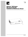
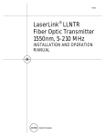
1
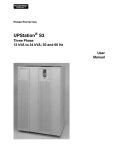
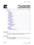
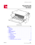
PowerWorx® Power Distribution Products
Traditional GMT Series Fuse Panel
User Manual
ADCP-80-582 • Issue 1 • 9/2009
23657-A
1670916 Rev A
ADCP-80-582 • Issue 1 • 9/2009 • Preface
COPYRIGHT
© 2009, ADC Telecommunications, Inc.
All Rights Reserved
REVISION HISTORY
ISSUE
DATE
1
9/2009
REASON FOR CHANGE
Original.
TRADEMARK INFORMATION
ADC is a registered trademark of ADC Telecommunications, Inc. PowerWorx is a registered trademark of ADC
Telecommunications, Inc.
DISCLAIMER OF LIABILITY
Contents herein are current as of the date of publication. ADC reserves the right to change the contents without prior notice. In no
event shall ADC be liable for any damages resulting from loss of data, loss of use, or loss of profits and ADC further
+disclaims any and all liability for indirect, incidental, special, consequential or other similar damages. This disclaimer of
liability applies to all products, publications and services during and after the warranty period.
This publication may be verified at any time by contacting ADC’s Technical Assistance Center at 1-800-366-3891, extension 73475
(in U.S.A. or Canada) or 952-917-3475 (outside U.S.A. and Canada), or by e-mail to [email protected].
ADC Telecommunications, Inc.
P.O. Box 1101, Minneapolis, Minnesota 55440-1101
In U.S.A. and Canada: 1-800-366-3891
Outside U.S.A. and Canada: (952) 938-8080
Fax: (952) 917-1717
Page ii
ADCP-80-582 • Issue 1 • 9/2009 • Preface
TABLE OF CONTENTS
Content
Page
About This Manual . . . . . . . . . . . . . . . . . . . . . . . . . . . . . . . . . . . . . . . . . . . . . . . . . . . . . . . . . . . . . . . . . . . . . . . . . . . v
Standards Certification . . . . . . . . . . . . . . . . . . . . . . . . . . . . . . . . . . . . . . . . . . . . . . . . . . . . . . . . . . . . . . . . . . . . . . . . v
Admonishments . . . . . . . . . . . . . . . . . . . . . . . . . . . . . . . . . . . . . . . . . . . . . . . . . . . . . . . . . . . . . . . . . . . . . . . . . . . . . v
General Safety Precautions . . . . . . . . . . . . . . . . . . . . . . . . . . . . . . . . . . . . . . . . . . . . . . . . . . . . . . . . . . . . . . . . . . . . . v
1
PRODUCT DESCRIPTION . . . . . . . . . . . . . . . . . . . . . . . . . . . . . . . . . . . . . . . . . . . . . . . . . . . . . . . . . . . . . . . . . . 1
1.1
General Description . . . . . . . . . . . . . . . . . . . . . . . . . . . . . . . . . . . . . . . . . . . . . . . . . . . . . . . . . . . . . . . . 1
1.2
Product Options and Examples . . . . . . . . . . . . . . . . . . . . . . . . . . . . . . . . . . . . . . . . . . . . . . . . . . . . . . . . 3
1.3
Functional Description . . . . . . . . . . . . . . . . . . . . . . . . . . . . . . . . . . . . . . . . . . . . . . . . . . . . . . . . . . . . . . 7
1.4
Specifications and Dimensions . . . . . . . . . . . . . . . . . . . . . . . . . . . . . . . . . . . . . . . . . . . . . . . . . . . . . . . . 8
1.5
Accessories . . . . . . . . . . . . . . . . . . . . . . . . . . . . . . . . . . . . . . . . . . . . . . . . . . . . . . . . . . . . . . . . . . . . 12
2
UNPACKING . . . . . . . . . . . . . . . . . . . . . . . . . . . . . . . . . . . . . . . . . . . . . . . . . . . . . . . . . . . . . . . . . . . . . . . . . . 12
3
PRE-INSTALLATION TESTING . . . . . . . . . . . . . . . . . . . . . . . . . . . . . . . . . . . . . . . . . . . . . . . . . . . . . . . . . . . . . . 12
4
INSTALLATION . . . . . . . . . . . . . . . . . . . . . . . . . . . . . . . . . . . . . . . . . . . . . . . . . . . . . . . . . . . . . . . . . . . . . . . . 13
4.1
Installing the Cable Management Bar. . . . . . . . . . . . . . . . . . . . . . . . . . . . . . . . . . . . . . . . . . . . . . . . . . . 14
4.2
Mounting the Panel on the Rack . . . . . . . . . . . . . . . . . . . . . . . . . . . . . . . . . . . . . . . . . . . . . . . . . . . . . . 14
4.3
Connecting Grounding Cables . . . . . . . . . . . . . . . . . . . . . . . . . . . . . . . . . . . . . . . . . . . . . . . . . . . . . . . . 16
4.4
Connecting Alarms . . . . . . . . . . . . . . . . . . . . . . . . . . . . . . . . . . . . . . . . . . . . . . . . . . . . . . . . . . . . . . . 17
4.5
5
6
7
4.4.1
Wire Wrap Alarm Terminals . . . . . . . . . . . . . . . . . . . . . . . . . . . . . . . . . . . . . . . . . . . . . . . . . . 18
4.4.2
Screw-Down Barrier Strip Alarm Terminals. . . . . . . . . . . . . . . . . . . . . . . . . . . . . . . . . . . . . . . . 19
Connecting Power Input . . . . . . . . . . . . . . . . . . . . . . . . . . . . . . . . . . . . . . . . . . . . . . . . . . . . . . . . . . . . 19
4.5.1
Two-Hole Compression Lug . . . . . . . . . . . . . . . . . . . . . . . . . . . . . . . . . . . . . . . . . . . . . . . . . . 20
4.5.2
Set Screw Barrel Connector . . . . . . . . . . . . . . . . . . . . . . . . . . . . . . . . . . . . . . . . . . . . . . . . . . 21
4.5.3
Connection Polarity Test. . . . . . . . . . . . . . . . . . . . . . . . . . . . . . . . . . . . . . . . . . . . . . . . . . . . . 21
4.6
Installing Fuse Designation Card . . . . . . . . . . . . . . . . . . . . . . . . . . . . . . . . . . . . . . . . . . . . . . . . . . . . . . 22
4.7
Installing Fuse Designation Pin Holders . . . . . . . . . . . . . . . . . . . . . . . . . . . . . . . . . . . . . . . . . . . . . . . . . 22
4.8
Connecting Power Output . . . . . . . . . . . . . . . . . . . . . . . . . . . . . . . . . . . . . . . . . . . . . . . . . . . . . . . . . . . 23
4.8.1
Set Screw Barrel Terminal Strip . . . . . . . . . . . . . . . . . . . . . . . . . . . . . . . . . . . . . . . . . . . . . . . 23
4.8.2
Screw-Down Barrier Terminal Strip . . . . . . . . . . . . . . . . . . . . . . . . . . . . . . . . . . . . . . . . . . . . . 23
PRE-OPERATION TESTING . . . . . . . . . . . . . . . . . . . . . . . . . . . . . . . . . . . . . . . . . . . . . . . . . . . . . . . . . . . . . . . . 24
5.1
Wiring Connections Measurement . . . . . . . . . . . . . . . . . . . . . . . . . . . . . . . . . . . . . . . . . . . . . . . . . . . . . 24
5.2
Fuse Alarm Relay Check. . . . . . . . . . . . . . . . . . . . . . . . . . . . . . . . . . . . . . . . . . . . . . . . . . . . . . . . . . . . 25
5.3
Fuse Alarm Indicator Test . . . . . . . . . . . . . . . . . . . . . . . . . . . . . . . . . . . . . . . . . . . . . . . . . . . . . . . . . . . 25
OPERATION . . . . . . . . . . . . . . . . . . . . . . . . . . . . . . . . . . . . . . . . . . . . . . . . . . . . . . . . . . . . . . . . . . . . . . . . . . 25
6.1
Connecting New Equipment. . . . . . . . . . . . . . . . . . . . . . . . . . . . . . . . . . . . . . . . . . . . . . . . . . . . . . . . . . 25
6.2
Installing or Replacing a Fuse . . . . . . . . . . . . . . . . . . . . . . . . . . . . . . . . . . . . . . . . . . . . . . . . . . . . . . . . 26
MAINTENANCE . . . . . . . . . . . . . . . . . . . . . . . . . . . . . . . . . . . . . . . . . . . . . . . . . . . . . . . . . . . . . . . . . . . . . . . . 27
7.1
Inspection . . . . . . . . . . . . . . . . . . . . . . . . . . . . . . . . . . . . . . . . . . . . . . . . . . . . . . . . . . . . . . . . . . . . . 27
7.2
Cleaning . . . . . . . . . . . . . . . . . . . . . . . . . . . . . . . . . . . . . . . . . . . . . . . . . . . . . . . . . . . . . . . . . . . . . . 27
7.3
Adjustments . . . . . . . . . . . . . . . . . . . . . . . . . . . . . . . . . . . . . . . . . . . . . . . . . . . . . . . . . . . . . . . . . . . . 27
8
CUSTOMER INFORMATION AND ASSISTANCE . . . . . . . . . . . . . . . . . . . . . . . . . . . . . . . . . . . . . . . . . . . . . . . . . . . 28
A
APPENDIX A: ALLOWABLE AMPACITIES OF INSULATED CONDUCTORS. . . . . . . . . . . . . . . . . . . . . . . . . . . . . . . . . . 29
Page iii
© 2009, ADC Telecommunications, Inc.
ADCP-80-582 • Issue 1 • 9/2009 • Preface
This page is intentionally blank.
Page iv
© 2009, ADC Telecommunications, Inc.
ADCP-80-582 • Issue 1 • 9/2009 • Preface
ABOUT THIS MANUAL
This user manual describes the PowerWorx Traditional GMT Series Fuse Panel, and provides all
information required to install and operate this product. The GMT panel comes in a number of
different configurations, all of which are covered in this manual.
Note: In this manual, the product is referred to as “the GMT panel.”
The GMT panel is used to supply protected dc power to the equipment typically installed in a
central office, multimedia headend, remote site, CEV, or other restricted access location
requiring protected dc power.
STANDARDS CERTIFICATION
This panel meets UL, Telcordia (formerly Bellcore), NEC 1999, CSA, NEBS Level 3, IEC, and
CE standards.
ADMONISHMENTS
Important safety admonishments are used throughout this manual to warn of possible hazards to
persons or equipment. An admonishment identifies a possible hazard and then explains what
may happen if the hazard is not avoided. The admonishments — in the form of Dangers,
Warnings, and Cautions — must be followed at all times. These warnings are flagged by use of
the triangular alert icon (seen below), and are listed in descending order of severity of injury or
damage and likelihood of occurrence.
Danger: Danger is used to indicate the presence of a hazard that will cause severe personal
injury, death, or substantial property damage if the hazard is not avoided.
Warning: Warning is used to indicate the presence of a hazard that can cause severe personal
injury, death, or substantial property damage if the hazard is not avoided.
Caution: Caution is used to indicate the presence of a hazard that will or can cause minor
personal injury or property damage if the hazard is not avoided.
GENERAL SAFETY PRECAUTIONS
-
Warning: The fuse panel uses electrical voltage and current levels that may be considered an
electrical hazard per GR-1089. Only qualified personnel should be allowed to install, operate,
maintain, or otherwise come into contact with this equipment when energized. Only insulated
tools should be used on energized elements of the panel.
Warning: Disconnect or turn off the power before connecting the fuse panel input or output
wires. This may require turning off the system office battery input at the battery distribution fuse
bay or removing fuses at the fuse panel.
Page v
© 2009, ADC Telecommunications, Inc.
ADCP-80-582 • Issue 1 • 9/2009 • Preface
Caution: Using the wrong fuse may cause damage to the protected equipment or the fuse panel.
When replacing a fuse, make sure the replacement fuse rating does not exceed 15 Amps rating
(10 Amps rating for panels with a maximum fuse rating of 10 Amps), and is the correct type and
correct current rating as required by the protected equipment.
Warning: Wet conditions increase the potential for receiving an electrical shock when
installing or using electrically-powered equipment. To prevent electrical shock, never install or
use electrical equipment in a wet location or during a lightning storm.
Page vi
© 2009, ADC Telecommunications, Inc.
ADCP-80-582 • Issue 1 • 9/2009
1
PRODUCT DESCRIPTION
The PowerWorx Traditional GMT Series Fuse Panel (hereafter called “the GMT panel”)
provides GMT type fuse protection for telecommunications products used in central offices,
multimedia headends, remote sites, and other locations requiring fused power.
1.1
General Description
The GMT panel is available in a number of different configurations, but all GMT panels have
common features illustrated below in a front view (Figure 1) and rear view (Figure 2) of a
typical panel. These features include:
• Use of GMT fuses, as the product name implies—The fuses may be arranged in either
one or two strips providing 10, 20, or 40 fuse positions. Fuse rating may vary from 0.2 to
15 Amps. The GMT fuses are positioned in a user-friendly, upside-down orientation for
enhanced fuse visibility when looking from below the panel (since the panel is usually
installed in the top rack position).
• Input amperage rating of 65 Amps per power bus—Different models may have either
one or two buses. Panels having two buses are rated for an input amperage of 130 Amps
(65 Amps per bus).
Caution: See Section 6.3 on page 28 for maximum bus loading condition.
Warning: Use of one bus only on a dual bus panel will result in false alarms for the unused bus.
Power is required on both buses on a dual bus panel for normal operation.
• Self-configuring voltage and polarity capabilities—The GMT panel operates using an
input voltage of ±24 Vdc (with a range of ±21 to ±30 Vdc) or ±48 Vdc (with a range of
±42 to ±56 Vdc). Output voltage is the same as the input voltage.
• Ability to be mounted on either a 19-inch or 23-inch EIA or WECO rack—All GMT
panels are shipped with mounting brackets accommodating either selection. All GMT
panels may also be mounted either flush or with a range of recess options.
• High-brilliance, field replaceable LEDs—These LEDs may be either of two types, a
green power-on indicator or a red fuse alarm indicator. Most models have one of each type
of indicator per power bus. One model has only a fuse alarm indicator. The indicators
perform the obvious function of indicating when power is present or when a fuse is faulted
causing a loss of power in any output of the bus.
• Sturdy chassis design—GMT panels are constructed of 16-gauge cold rolled steel. All
panels come with a lifetime warranty. Panel color may be either putty or black.
• Agency approval—GMT panels are compliant with all major standards including UL,
NEBS Level 3, Telcordia (Bellcore), NEC 1999, CSA, IEC, and CE, as indicated on the
certification label on each chassis.
Page 1
© 2009, ADC Telecommunications, Inc.
ADCP-80-582 • Issue 1 • 9/2009
• Sturdy input and output termination—GMT panels provide secure, reliable physical
connections for power input and output using two-hole compression lug or set screw barrel
termination for input and screw-down or set screw termination for output.
• Alarm connection—GMT panels provide external fuse failure relay dry contacts for
audio, visual, and remote alarms.
• Fuse and voltage labels—All GMT panels come with fuse value designation pin holders,
fuse designation card and holder, and voltage designation label.
• Two-post grounding—All GMT panels provide two-post termination for chassis
grounding. The lugs are spaced so that a two-hole compression lug can be used for
termination of a larger wire (up to #2 AWG).
• Protective covers—All GMT panels have easily-removable, clear polycarbonate covers
for input and output power terminations.These covers prevent against accidental contact
with electric power.
AGENCY
CERTIFICATION
UNIVERSAL
MOUNTING
BRACKETS
"UPSIDE DOWN"
USER FRIENDLY
GMT FUSE
HOLDERS
STURDY
CHASSIS
DESIGN
23656-A
FUSE VALUE
DESIGNATION
PIN HOLDERS
FIELD-REPLACEABLE
HIGH BRILLIANCE LEDS
Figure 1. Typical GMT Panel (Front View)
Page 2
© 2009, ADC Telecommunications, Inc.
ADCP-80-582 • Issue 1 • 9/2009
TWO-POST
GROUNDING
POWER OUTPUT TO
NETWORK EQUIPMENT
(SCREW DOWN OR ALARM OUTPUT
FOR SYSTEM
SET SCREW)
MANAGEMENT
PROTECTIVE
COVER
PROTECTIVE
COVERS
18736-A
INPUT AMPERAGE
UP TO 65 AMPS
(SET SCREW BARREL
OR COMPRESSION LUG)
Figure 2. Typical GMT Panel (Rear View)
1.2
Product Options and Examples
The GMT fuse panel is available in various configurations with options as follows:
• Standard (front and rear) access or total front access.
• Single or dual power bus. Single bus options provide 10, 20, or 40 fuse positions. Dual bus
options provide dual 10 or dual 20 fuse positions.
• Two types of input terminations: two-hole compression lug or set screw barrel.
• Two types of output terminations: screw-down barrier or set screw barrel.
• Two types of alarm terminations: screw-down barrier or wire-wrap pins.
• Various LED configurations from a single LED for both buses (as shown in Figure 3) to
one power on LED and one fuse failure LED for each bus (as shown in Figure 5).
• Two chassis colors: putty or black.
Figure 3 shows a front view of a dual bus GMT panel. Each bus provides ten fuse positions and
ten outputs. This panel has a single fuse alarm indicator.
Page 3
© 2009, ADC Telecommunications, Inc.
ADCP-80-582 • Issue 1 • 9/2009
UL/CSA/CE
LABEL
MOUNTING
BRACKET
(23-IN. SHOWN)
23658-A
FUSE ALARM
INDICATOR
(BOTH BUSES
TOGETHER)
GMT FUSE
HOLDERS
(A AND B)
Figure 3. Dual Bus GMT Panel
Figure 4 shows a rear view of the same panel. This panel exemplifies several options including
compression lug power inputs, screw-down power outputs, and screw-down alarm terminations.
The figure also shows examples of the two-post grounding contacts and protective covers
provided with all models.
Figure 5 shows a front view of the total front access panel. This panel also has dual 10-position
power buses, compression lug power inputs, screw-down alarm terminations, two post
grounding contacts, and protective covers. It has screw-down power output terminations.
Page 4
© 2009, ADC Telecommunications, Inc.
ADCP-80-582 • Issue 1 • 9/2009
GROUNDING
POSTS
OUTPUT CONNECTORS
(SCREW DOWN
TYPE SHOWN)
18738-A
ALARM
CONTACTS
INPUT CONNECTORS
(COMPRESSION LUG SHOWN)
PROTECTIVE
COVERS
PROTECTIVE
COVERS
Figure 4. Rear View of Dual Bus Panel
UNIVERSAL
MOUNTING
BRACKETS
FUSE FAILURE
INDICATORS
(A AND B)
ALARM
CONTACTS
POWER FAILURE
INDICATORS
(A AND B)
GMT FUSE
HOLDERS
(A AND B)
CABLE
RINGS
OUTPUT CONNECTORS
(SCREW DOWN
TYPE SHOWN)
GROUNDING
POSTS
18739-A
PROTECTIVE
COVERS
PROTECTIVE
COVERS
INPUT CONNECTORS
(COMPRESSION LUG SHOWN)
Figure 5. Total Front Access Panel
Page 5
© 2009, ADC Telecommunications, Inc.
ADCP-80-582 • Issue 1 • 9/2009
Figure 6 shows front and rear views of a single bus panel with ten fuse positions and two LEDs
(power-on and fuse alarm). This panel illustrates the larger-size protective covers provided for
panels having set screw barrel power input terminations. This panel is provided with a universal
mounting bracket that can be used for either 19-inch or 23-inch rack mounting.
VENTS
FUSE OR POWER
FAILURE
INDICATOR
(RED LED)
UL/CSA/CE
LABEL
GMT FUSE HOLDER
(10 POSITION SHOWN)
FUSE VALUE
DESIGNATION
PIN HOLDER
POWER-ON
INDICATOR
(GREEN LED)
FRONT VIEW
PROTECTIVE COVER IN PLACE
OVER INPUT AND OUTPUT
POWER, GROUND, AND ALARM
CONTACT CONNECTIONS
REAR VIEW
UNIVERSAL
MOUNTING
BRACKETS (2)
(INSTALLED
FOR 23-IN. (58.42 CM)
RACK MOUNTING)
23661-A
Figure 6. Single Bus GMT Panel
Figure 7 shows a panel with set screw barrel type input and output terminals.
Page 6
© 2009, ADC Telecommunications, Inc.
ADCP-80-582 • Issue 1 • 9/2009
PROTECTIVE COVER
MOUNTING STANDOFFS
(2 SETS)
ALARM CONTACT CONNECTOR
(SCREW-DOWN BARRIER
TERMINAL STRIP TYPE SHOWN)
CHASSIS
GROUND
TERMINALS
INTERNAL CONNECTION POINT.
DO NOT REMOVE CAPS.
OUTPUT CONNECTORS
(SET SCREW BARREL
TERMINAL STRIP
TYPE SHOWN)
INPUT CONNECTORS
(SET SCREW BARREL
TYPE SHOWN)
13501-A
Figure 7. Panel With Set Screw Input and Output Terminals (Rear View)
1.3
Functional Description
Functionally, the central feature of any GMT panel is the power bus, which receives power from
an external source, passes the power through an array of GMT fuses, and distributes the power
to the connected equipment. Depending on the product model, a particular panel may have
either one or two power buses. Figure 8 is a schematic of a dual power bus.
Warning: Use of one bus only on a dual bus panel will result in false alarms for the unused bus.
Power is required on both buses on a dual bus panel for normal operation.
FEED B FUSE ALARM
FEED A FUSE ALARM
FEED B POWER INDICATOR
FEED A POWER INDICATOR
FEED A
POWER OUTPUT
FEED A
FUSE ARRAY
FEED A
VOLTAGE
FEED B
POWER OUTPUT
ALARM
CIRCUIT
ALARM
OUTPUT
FEED A
RETURN
BATTERY A
ALARM
CIRCUIT
(3)
(3)
FEED B
FUSE ARRAY
FEED B
RETURN
(3)
FEED B
VOLTAGE
BATTERY B
AUDIO VISUAL REMOTE
18822-AR
Figure 8. Fuse Panel Block Diagram
Page 7
© 2009, ADC Telecommunications, Inc.
ADCP-80-582 • Issue 1 • 9/2009
As shown, each bus has two input power connectors, labeled “BATT” (battery) and “RTN”
(return). In each bus circuit, current flows from the input connectors to the fuse array. When a
fuse is installed in a fuse holder, the circuit is completed to the output connectors. When a fuse
fails, the input power bus is connected through the GMT fuse conducting flag to the fuse failure
alarm relay, which causes switch closures at the alarm contacts connection. The alarm condition
is reported both on the front console (LED) and on the alarm output dry contacts (audio, visual,
and remote) located on the rear of the panel except for total front access panel.
All GMT panels also provide an alarm reporting function, which indicates when normal
function is interrupted due to lack of power or a failed fuse.
The alarm circuitry consists of alarm relays with form C contacts that are terminated at a
connector or wire-wrap pin block on the outside of the fuse panel. During normal operation, the
normally open (NO) contacts remain open and the normally closed (NC) contacts remain
closed. When a fuse fails, the NO contacts close, creating a connection from NO to common (C)
and the NC contacts open. In panels with a power on indicator, lack of power creates the same
condition. The alarm contact closures may be used as loop closures in alarm systems. The
current for each fuse failure alarm relay (set of three contacts) is 1.0 Amp maximum.
1.4
Specifications and Dimensions
Table 1 lists specifications for the Traditional GMT Series Fuse Panel.
Table 1. Traditional GMT Panel Specifications
PARAMETER
SPECIFICATION
Standards
Meets UL, Telcordia (Bellcore), NEC 1999,
CSA, NEBS Level 3, IEC, and CE standards
REMARKS
Physical
Configuration options
Single bus (S) or dual bus (D);
10, 20, or 40 fuse positions (single bus);
10/10 or 20/20 fuse positions (dual bus);
standard (front and rear) or total front access;
2-hole lug or set screw barrel power input;
screw-down or set screw barrel power output;
wire wrap or screw-down alarm terminations
Weight
Approximately 10 lbs. (4.5 Kg)
Dimensions (HxWxD)
Standard access: 1.75 x 17.12 x 8.0 inches
(4.44 x 43.28 x 20.32 cm). See Figure 9
Total front access: 3.5 x 21.25 x 4.0 inches
(8.89 x 53.97 x10.16 cm). See Figure 10
Chassis material
Cold-rolled 16-gauge steel
Chassis color
Putty white or black powder coat
Rack mount
19--inch (48.3 cm) or 23-inch (58.42 cm)
Page 8
© 2009, ADC Telecommunications, Inc.
For details refer to
ADC catalog 1273819
available online
at www.adc.com
Dimensions do not include depth of
power connectors, alarm lamps, or
fuses.
Clear polycarbonate protective covers
WEC0 or EIA hole spacing
ADCP-80-582 • Issue 1 • 9/2009
Table 1. Traditional GMT Panel Specifications, continued
PARAMETER
SPECIFICATION
REMARKS
Recess options
Standard panels: flush or recessed 1 inch (2.54 cm), 2 inches (5.08 cm), 3 inches (7.62
cm), or 4 inches (10.16 cm); total front access panel: flush or recessed 1 inch (2.54 cm)
or 2 inches (5.08 cm)
Environmental
Operating temperature
–5º C to +55º C
Storage temperature
–45º C to +85º C
Humidity range
0% to 95% humidity
Altitude range
–197 ft. (60 m) to 13,000 ft. (3.96 km)
Fire rating
All components UL94-V1 or better
Earthquake design
Zone 4
Acoustic noise
0 dBA above ambient
Heat dissipation (fully
loaded)
14 watts maximum @ 65 Amps
28 watts maximum @ 130 Amps
Heat dissipation (no load)
1 watt per bus
No condensation
Electrical
Operating voltages
±24 Vdc (±21 to ±30 Vdc tolerance) or
±48 Vdc (±42 to ±56 Vdc tolerance)
Panel automatically senses input voltage and adjusts as necessary
Input current
65 Amps (maximum) per bus
Dual bus: 130 Amps
Fuse type
GMT
0.2 to 15 Amp rating (see below)
Fuse mounting positions
Single bus: 10, 20, or 40;
dual bus: 10/10 or 20/20
Input power connection
2-hole compression lug (stud-type) or
Accepts wire up to #2 AWG
screw-down barrel connector
Accepts wire up to #6 AWG
0.25 inch holes on 0.625 inch centers
Panel ships with two 2-hole lugs
(accepting 6 AWG) per bus
Screw-down barrier terminal strip or
Max lug width 0.20 inches (0.51 cm)
# 12-22 AWG*
set screw barrel terminal strip:
# 12-22 AWG*
Output power connection
Maximum fuse size and
S10, D10 with screw-down output: 15 Amps
range of bare wire accepted*
S10, D10 with set screw output: 15 Amps
(S = single bus, D = dual)
S20 with screw-down output: 15 Amps
*Output terminals accept a
bare wire for termination in this
wire size range.
Warning: Size wire according
to local practice and code,
referring to Appendix A for
ampacity guidelines.
# 12-22 AWG*
# 12-24 AWG*
# 12-20 AWG*
S20 with set screw output: 15 Amps
# 12-24 AWG*
S40 with screw-down output: 10 Amps
# 16-24 AWG*
S40 with set screw output: 15 Amps
# 12-24 AWG*
D20 with screw-down output: 10 Amps
# 16-24 AWG*
D20 with set screw output: 15 Amps
# 12-24 AWG*
Page 9
© 2009, ADC Telecommunications, Inc.
ADCP-80-582 • Issue 1 • 9/2009
Table 1. Traditional GMT Panel Specifications, continued
PARAMETER
SPECIFICATION
REMARKS
Alarm contact
Wire wrap or screw-down barrier terminal
strip
Alarm contact voltage
110 Vac, 125 Vdc maximum
Alarm contact current
1 Amp maximum
Grounding connections
Two #10 studs
0.25 inch holes on 0.625 inch centers
Indicator LEDs
Power on: lights green when power is present
One LED per bus on most models;
some models do not have this LED
Fuse failure: Lights red when any fuse fails
One LED per bus on most models;
some models have one LED for both
buses together
Mounting bracket chassis
screws
15 pound-force inches
1.7 Newton meters
Mounting bracket rack
screws
27 pound-force inches
3.1 Newton meters
Input power connections
Refer to installation drawing
Output power connections
Refer to installation drawing
Grounding stud nuts
23 pound-force inches
Torque
2.6 Newton meters
Figure 9 shows dimensions for the standard access panel. Figure 10 shows dimensions for the
total front access panel.
Page 10
© 2009, ADC Telecommunications, Inc.
ADCP-80-582 • Issue 1 • 9/2009
9.10 IN.
(23.11 CM)
8.00 IN.
(20.32 CM)
17.12 IN.
(43.48 CM)
23.00 IN.
(58.42 CM)
22.31 IN.
(56.67 CM)
1.13 IN.
(2.87 CM)
1.75 IN.
(4.45 CM)
23663.A
Figure 9. Standard Access Panel Dimensions
5.25 IN.
(13.34 CM)
4.00 IN.
(10.16 CM)
23.00 IN.
(58.42 CM)
22.31 IN.
(56.67 CM)
2.75 IN.
(6.99 CM)
3.50 IN.
(8.89 CM)
23662-A
Figure 10. Total Front Access Panel Dimensions
Page 11
© 2009, ADC Telecommunications, Inc.
ADCP-80-582 • Issue 1 • 9/2009
1.5
Accessories
The following accessories are available for a GMT panel:
• GMT fuses. Standard fuse rating from 0.2 Amp to 15.0 Amps.
• Fuse designation pin holder.
• Colored, standard value, fuse designation pins.
• Cable management bar with mounting screws.
• GMT fuse puller.
• Compression lugs for #2, #4, #6, and #14 AWG wire.
• Fuse designation card holder kit.
2
UNPACKING
Unpack and inspect the various components as follows:
1. Inspect the exterior of the shipping container for evidence of handling that may have
damaged the components in the container.
2. Unpack each container while carefully checking the contents for damage and verify with
the packing slip.
3. File a claim with the commercial carrier and notify ADC Customer Service if damage is
detected or if parts are missing. Save damaged cartons for inspection by the carrier.
4. For repair, replacement, and warranty information, refer to Section 8 on page 30.
3
PRE-INSTALLATION TESTING
Each unit is thoroughly tested at the ADC Telecommunications factory. Before installation, an
onsite resistance test is recommended, however, to assure that no damage has occurred during
shipping or handling. If present, both bus A and bus B input circuits need to be tested.
Caution: This equipment employs electrical voltage and amperage levels which may be
considered an electrical hazard. Care should be exercised to assure that only qualified
personnel are allowed to install, operate, maintain, or otherwise come in contact with this
equipment when the fuse panel is energized. Only insulated tools should be used on energized
elements of the fuse panel.
Caution: Before performing this test, verify that the input and output power is not connected to
the fuse panel connectors.
Page 12
© 2009, ADC Telecommunications, Inc.
ADCP-80-582 • Issue 1 • 9/2009
To perform the resistance test, measure the resistance at each bus input with a multimeter
connected to the BATT and RTN input terminals. You should obtain a reading of at least 500
ohms. (Some meters will indicate a resistance of several Megohms because their input voltage is
not high enough to break down the forward conductance of the diodes used in the alarm circuit.)
Any resistance higher than 500 ohms is acceptable.
4
INSTALLATION
Observe the following guidelines when installing the fuse panel:
• Mount the fuse panel in the uppermost area of the rack to reduce exposure of the power
wiring. Allow at least 1.75 inches (4.45 cm) of air space (one rack space) on the top and
bottom of the panel for cooling.
• If necessary, relocate any device that currently occupies the top space on the rack.
• Use common hand tools to install the fuse panel. You will find a power screwdriver helpful
in installing the self-tapping screws that attach the mounting brackets to the rack.
Danger: Never install telephone equipment in a wet location or during a lightning storm. When
installing or modifying telephone lines, disconnect lines at the network interface before working
with uninsulated lines or terminals to prevent electrical shock.
Danger: Do not install fuses in fuse panel or power source until you have completed the power
wiring connections.
Caution: This equipment employs electrical voltage and amperage levels which may be
considered an electrical hazard. Care should be exercised to assure that only qualified
personnel are allowed to install, operate, maintain, or otherwise come in contact with this
equipment when the fuse panel is energized. Only insulated tools should be used on energized
elements of the fuse panel.
Page 13
© 2009, ADC Telecommunications, Inc.
ADCP-80-582 • Issue 1 • 9/2009
4.1
Installing the Cable Management Bar
The cable management bar is a product accessory not provided with the panel. If a cable
management bar was ordered separately, mount the bar on the panel before installing the panel
on the rack. Use the 1/4-inch (6.35 mm) long 4-40 screws supplied with the cable management
bar. The cable management bar can be recess-mounted using the mounting holes closest to the
front of the pane. Install the cable management bar as shown in Figure 11.
MOUNTING BRACKET
INSTALLED FOR
23-IN. (58.42 CM)
RACK MOUNTING
ATTACH TO
EITHER SET
OF 3 HOLES
CABLE
MANAGEMENT
BAR
13035-E
Figure 11. Installing the Cable Management Bar
4.2
Mounting the Panel on the Rack
The GMT panel can be mounted in either a 19-inch (48.26-cm) rack or a 23-inch (58.42-cm)
rack, using WECO 1.00-inch (2.54 cm) or EIA 1.25-inch (3.18 cm) hole spacing. The standard
(front and rear access) panels can be flush mounted or recessed 1 inch (2.54 cm), 2 inches (5.08
cm), 3 inches (7.62 cm), or 4 inches (10.16 cm). The total front access panel can be flush
mounted or recessed 1 inch (2.54 cm) or 2 inches (5.08 cm).
Mounting brackets are provided with the panel. Some panels have universal mounting brackets
that can be oriented in either of two ways to accommodate the different rack widths. Other
panels have two different sets of mounting brackets, one set for each rack width. Hardware for
mounting the brackets is also provided, as indicated in the following procedure in the figures
showing rack mount positions.
Note: ETSI rack mounting using ETSI mounting brackets is also available.
To install the panel, use the following procedure:
1. Determine rack width, rack type, and flush-versus-recess selection.
Page 14
© 2009, ADC Telecommunications, Inc.
ADCP-80-582 • Issue 1 • 9/2009
2. Locate the mounting brackets and determine whether they are the universal or specific
rack width type. The universal brackets have a triangular pattern of holes as shown in
Figure 12.
19-IN. (48.26 CM) RACK,
MOUNT ON FRAME,
USE 3/8-IN. (9.525 MM) LONG
SCREWS AND WASHERS
23-IN. (58.42 CM) RACK,
MOUNT ON FUSE PANEL,
USE 1/4-IN. (6.350 MM) LONG
FLATHEAD SCREWS
23-IN. (58.42 CM) RACK,
MOUNT ON FRAME,
USE 3/8-IN. (9.525 MM) LONG
SCREWS AND WASHERS
19-IN. (48.26 CM) RACK,
MOUNT ON FUSE PANEL,
USE 1/4-IN. (6.350 MM) LONG
FLATHEAD SCREWS
13034-C
Figure 12. Universal Mounting Brackets
3. If the mounting bracket is the universal type, mount the bracket on the panel using the
holes and hardware indicated in Figure 12.
4. If the mounting brackets are the specific width type, select the 19-inch or 23-inch brackets,
and orient and attach the mounting bracket on the panel referring to Figure 13.
19-INCH RACK
MOUNTING
BRACKET (2)
5/16-INCH (7.94 MM)
8-32 FLAT-HEAD
THREAD-FORMING
SCREWS
23-INCH RACK
MOUNTING
BRACKET (2)
TIGHTEN MOUNTING SCREWS
TO 15 POUND-FORCE INCHES
(1.7 NEWTON METERS) OF TORQUE
23664-A
Figure 13. Selecting and Orienting Specific Width Brackets
Page 15
© 2009, ADC Telecommunications, Inc.
ADCP-80-582 • Issue 1 • 9/2009
5. Fasten the panel to the rack using the hardware provided, as shown in Figure 14. Tighten
the screws to 27 pound-force inches (3.1 Newton-meters).
Note: Figure 14 shows a single height (standard access) panel with a specific width
mounting bracket. The panel being installed could be a double-height (total front access)
panel. The mounting brackets could be either the specific width type or universal type.
DETAIL DRAWING OF
MOUNTING SCREWS
AND WASHERS
USE #12 STAR WASHERS INSTEAD OF FLAT
WASHERS IF REQUIRED BY LOCAL PRACTICE
23665-A
NOTE:
PROVIDE ONE RACK UNIT OF SPACE ABOVE AND BELOW
THE FUSE PANEL FOR AIR CIRCULATION.
Figure 14. Mounting the Panel on the Rack
4.3
Connecting Grounding Cables
Note: Use two #10 AWG wires if using both chassis ground connectors or one #6 AWG
wire if using a dual hole compression lug. For ampacity guidelines if needed, refer to
Appendix A in this manual. This procedure assumes use of two #10 AWG wires.
Use the following procedure to connect the fuse panel to an approved office ground source:
1. Obtain two lengths of 10 AWG wire for use as the chassis grounding wires.
Page 16
© 2009, ADC Telecommunications, Inc.
ADCP-80-582 • Issue 1 • 9/2009
2. Terminate one end of each wire with the #8 ring terminals provided (requires crimper).
3. Locate the C GND (chassis ground) studs at the rear of the fuse panel as shown in
Figure 15.
4. Connect the ring terminal end of each wire to one of the studs and secure using the nuts
with captive star washers provided (requires 11/32-inch socket). Tighten the stud nut to 23
pound-force inches (2.6 Newton meters) of torque.
5. Terminate the opposite ends of the wires to an approved office ground.
DETAIL DRAWING
OF GROUNDING
WIRE CONNECTION
18752-A
TIGHTEN STUD NUT TO
23 POUND-FORCE INCHES
(2.6 NEWTON METERS)
OF TORQUE
Figure 15. Chassis Grounding Connections
4.4
Connecting Alarms
The GMT panel provides external terminals for system use in detecting an alarm condition
within the panel. These terminals are arranged into rows, with each row having three terminals
labeled NO (Normally Open), C (Common), and NC (Normally Closed). Typically, there are
three such rows for each bus labeled Audio, Visual, and Remote, and intended for that purpose
in reporting the alarms to office personnel. The current for each fuse failure alarm relay (set of
three contacts) is 1.0 Amp maximum.
An alarm is reported when any of the following situations occurs:
• Fuse failure (in either bus if the panel has dual buses).
• Power failure (only panels with “power on” green LED).
Page 17
© 2009, ADC Telecommunications, Inc.
ADCP-80-582 • Issue 1 • 9/2009
The alarm circuitry consists of fuse failure alarm relays with form C dry contacts that are
terminated at the alarm terminals outside the panel. During normal operation, the normally open
(NO) contacts remain open and the normally closed (NC) contacts remain closed. When a fuse
fails (or when power is lost in a fuse panel with a power-on indicator), the NO contacts close,
creating a connection from NO to C, and the NC contacts open.
The number and appearance of the alarm terminals will depend upon the type of alarm
connector used in the panel being installed. Either of two types may be present:
• Wire wrap alarm terminals, shown in Figure 16.
• Screw-down barrier strip alarm terminals, shown in Figure 17.
Based on the type found, install the alarm cables referring to the following guidelines.
4.4.1
Wire Wrap Alarm Terminals
Use #22 to #26 AWG wire with the insulation stripped back. Refer to Figure 16.
18757-A
ALARM
CONNECTIONS
Figure 16. Wire Wrap Alarm Terminals
Page 18
© 2009, ADC Telecommunications, Inc.
ADCP-80-582 • Issue 1 • 9/2009
4.4.2
Screw-Down Barrier Strip Alarm Terminals
Use #12 to #24 AWG wire. Equip the wire leads with spade or crimp ring connectors having a
maximum width of 0.375 inch (9.525 mm). The terminals also accommodate copper wire
without lugs (with insulation stripped back). Use whichever method is dictated by local
practice. Tighten the nuts to 9 pound-force inches (1 Newton-meters). Refer to Figure 17.
18756-A
Figure 17. Screw-Down Barrier Strip Alarm Terminals
4.5
Connecting Power Input
Warning: Use of one bus only on a dual bus panel will result in false alarms for the unused bus.
Power is required on both buses on a dual bus panel for normal operation.
The panel may have either of two types of input power connectors:
• Two-hole compression lugs, shown in Figure 18.
• Set screw barrel connectors, shown in Figure 19.
Based on the type found, refer to the appropriate topic below.
Page 19
© 2009, ADC Telecommunications, Inc.
ADCP-80-582 • Issue 1 • 9/2009
Caution: Connect only the input voltage wire (labeled BATTERY or BATT, or labeled with the
voltage polarity and/or voltage value) to the connector on the fuse panel labeled BATT
(battery). Connect only the input return wire (labeled RTN, RETURN, or BATTERY GROUND)
to the connector on the fuse panel labeled RTN (return). If the wires are reversed, voltage could
be present on the fuse panel chassis and current could flow through the unfused return wiring in
the fuse panel. This condition causes damage to equipment in the frame in which the fuse panel
is installed and to equipment in adjacent frames.
Note: After installing the input wires, perform the connection polarity test described in
Subsection 4.5.3 on the following page. The purpose of this test is to verify that the wires
have been connected to the correct leads.
4.5.1
Two-Hole Compression Lug
Each set of two studs can accept different size 2-hole lugs, which can be used with a range of
wire sizes up to #2 AWG copper wire. In selecting wire size, follow local code, referring to the
ampacity guidelines provided in Appendix A of this manual. Two 2-hole lugs for use with #6
AWG wire are included with the fuse panel for each bus. Install the input power wires to the
studs as shown in Figure 18. For torque specifications, refer to installation drawing.
18755-A
Figure 18. Installing Power Input Using 2-Hole Compression Lugs
Page 20
© 2009, ADC Telecommunications, Inc.
ADCP-80-582 • Issue 1 • 9/2009
4.5.2
Set Screw Barrel Connector
On each connector, the barrel that is closest to the outside of the fuse panel and does not have a
cap on it is to be used to connect input power to the fuse panel power bus when installing the
fuse panel. The other barrel on each connector that is closest to the center of the fuse panel has a
cap over it and is not to be used or accessed. The set screw barrel input power connectors can
accept up to a #6 AWG copper wire. In selecting wire size, follow local code, referring to the
ampacity guidelines provided in Appendix A of this manual. The wire is inserted into the
connector, and the connector screw is screwed down, compressing the wire. Install the input
wires to the set screw barrel connectors as shown in Figure 19. For torque specifications, refer
to installation drawing.
INTERNAL CONNECTION POINT.
DO NOT REMOVE CAPS.
18754-A
INPUT CONNECTORS
Figure 19. Installing Power Input Using Set Screw Barrel Connectors
4.5.3
Connection Polarity Test
After completing the input wiring, use the following procedure to verify that the power input
wires are connected for correct polarity:
1. Verify that the input power cables are connected to the correct terminals.
2. Power up the fuse panel.
3. Using a multimeter set to measure DC voltage, measure the voltage between each input
power (RTN) terminal and chassis ground. The voltage level should be less than 2.0 Vdc.
4. If the RTN voltage is much higher, and reads out in the ±21 to ±30 Vdc range for the ±24
Vdc fuse panel or in the ±42 to ±56 Vdc range for the ±48 Vdc fuse panel, the input leads
are probably reversed. If this appears to be true, power down the panel. Disconnect the
BATT and RTN input lugs and switch them around. Power up the panel and check again to
verify that the higher voltage is on the BATT lug.
5. Power down the fuse panel if not already powered down.
6. If the problem is such that you can’t figure it out with these instructions, consult with ADC
Technical Assistance Center (TAC).
Page 21
© 2009, ADC Telecommunications, Inc.
ADCP-80-582 • Issue 1 • 9/2009
4.6
Installing Fuse Designation Card
Two types of fuse designation cards (shown in Figure 20) are provided with the fuse panel.
Either type can be used depending on customer need. A card holder is also provided with the
panel. The card holder has a pressure sensitive adhesive backing for attachment to the panel or
rack in a customer-selected location.
To install the card holder, remove the paper cover on the adhesive backing and press the card
holder on the panel or rack in the selected location. Select a fuse designation card, fill in the fuse
designations, place the card in the card holder.
Figure 20. Fuse Designation Cards
4.7
Installing Fuse Designation Pin Holders
A designation pin holder for each power bus is provided with the panel. This holder is designed
to hold color-coded pins that indicate fuse size. Designation pins are available from ADC as an
accessory item. Figure 21 shows a designation pin holder. To install the designation pin holder,
remove the paper cover on the adhesive backing and press the holder to the panel below the
appropriate fuse holder, as shown in the figure.
23666-A
DESIGNATION PIN HOLDER
AND FOAM ADHESIVE STRIP
Figure 21. Installing Designation Pin Holders
Page 22
© 2009, ADC Telecommunications, Inc.
ADCP-80-582 • Issue 1 • 9/2009
4.8
Connecting Power Output
The panel may be equipped with either of two types of power output:
• Screw-down barrier terminal strip, shown in Figure 22.
• Set-screw barrel terminal strip, shown in Figure 23
There will be two terminal strips per bus, labeled BATT and RTN. Based on the type of terminal
strip, select from the following topics for guidelines on connecting power output.
4.8.1
Set Screw Barrel Terminal Strip
The set screw barrel terminal strip, shown in Figure 22, accepts #12 to 22 AWG wire. In
selecting wire size, follow local code, referring to the ampacity guidelines provided in
Appendix A of this manual. For torque specifications, refer to the installation drawing provided
with the fuse panel.
18758-A
Figure 22. Set Screw Barrel Terminal Strip Power Output
Page 23
© 2009, ADC Telecommunications, Inc.
ADCP-80-582 • Issue 1 • 9/2009
4.8.2
Screw-Down Barrier Terminal Strip
The screw-down barrier terminal strip, shown in Figure 23, accepts #12 to 22 AWG wire. In
selecting wire size, follow local code, referring to the ampacity guidelines provided in
Appendix A of this manual. Equip wire leads with spade or crimp ring connectors that have a
maximum width of 0.20 inches (0.51 cm). The terminals also accommodate copper wire
without lugs (with insulation stripped back). Use whichever method is dictated by local
practice. For torque specifications, refer to the installation drawing provided with the fuse panel.
BUS A
BATT
18759-A
BUS A
RTN
Figure 23. Screw-Down Barrier Strip Power Output
5
PRE-OPERATION TESTING
After installation and before placing the fuse panel into service, complete the following final
tests.
Caution: This equipment employs electrical voltage and amperage levels which may be
considered an electrical hazard. Care should be exercised to assure that only qualified
personnel are allowed to install, operate, maintain, or otherwise come in contact with this
equipment when the fuse panel is energized. Only insulated tools should be used on energized
elements of the fuse panel.
Page 24
© 2009, ADC Telecommunications, Inc.
ADCP-80-582 • Issue 1 • 9/2009
5.1
Wiring Connections Measurement
Measure the torque of all input, output, and fuse failure alarm relay contact connections using a
torque screwdriver calibrated in force-pound inches (Newton-meters). For correct torque values,
refer to Table 1 on page 8 or the installation drawing provided with the fuse panel.
5.2
Fuse Alarm Relay Check
Power on the unit and check the fuse failure alarm contacts The fuse failure alarm relay should
indicate an open circuit between the common (C) contact and the normally open (NO) contact at
the alarm contacts. When input power is not applied, a short should be indicated between these
contacts and open circuit between the common (C) contact and the normally closed (NC) contact
at the alarm contacts.
5.3
Fuse Alarm Indicator Test
Place a fuse that has failed in one of the fuse positions on each bus. The visual fuse alarm
indicator(s) should change from unlighted to a red light, and the fuse failure alarm relay should
report an alarm.
6
OPERATION
Caution: This equipment employs electrical voltage and amperage levels which may be
considered an electrical hazard. Care should be exercised to assure that only qualified
personnel are allowed to install, operate, maintain, or otherwise come in contact with this
equipment when the fuse panel is energized. Only insulated tools should be used on energized
elements of the fuse panel.
Operation of the fuse panel consists of connecting new equipment when needed and removing
and replacing failed fuses. If a fuse fails, the alarm indicator lights, and the external and remote
alarms are activated (if present).
Page 25
ADCP-80-582 • Issue 1 • 9/2009
6.1
Connecting New Equipment
New fused equipment may be connected to unused output power circuits following installation
and testing of the fuse panel. Use the following procedure for connecting the output power
wires for new fused equipment to a previously installed fuse panel:
Warning: The fuse panel uses electrical voltage and current levels that may be considered an
electrical hazard per GR-1089. Only qualified personnel should be allowed to install, operate,
maintain, or otherwise come into contact with this equipment when energized. Only insulated
tools should be used on energized elements of the panel.
1. Remove the plastic protective cover from the output power terminal.
2. Locate an unused pair of terminals on the output terminal block and verify that a fuse is
not installed the corresponding fuse position.
3. Connect the output power wiring to the fuse panel output terminals as described in
subsection 4.8 on page 23.
Warning: Use care to avoid shorting out adjacent terminals when connecting new output
power wiring to a powered fuse panel. Shorting may cause injury and damage the fuse panel or
the connected fused equipment.
4. Install the plastic protective cover over the input and output power terminal blocks.
5. Install a fuse of the recommended size (as specified by the fused equipment manufacturer)
in the appropriate fuse position (see next topic).
6.2
Installing or Replacing a Fuse
Install a GMT fuse of the recommended size and type (as specified by the fused equipment
manufacturer) in each fuse position.
The current rating of the fuse (in Amperes) is indicated on the side of the fuse. The color of the
indicator also corresponds to the fuse size. Refer to the color code chart provided with
replacement fuses to identify the fuse size by color.
Caution: Using the wrong fuse may cause damage to the protected equipment or the fuse panel.
When replacing a blown fuse, make sure the replacement fuse is the same type and has exactly
the same current rating as the fuse being replaced and does not exceed 15 Amps rating (10
Amps rating for panels with a maximum fuse rating of 10 Amps) .
The fuse manufacturer recommends that GMT fuses rated 8 to 15 Amps be continuously
operated at no more than 80% of their nominal current rating.
Page 26
© 2009, ADC Telecommunications, Inc.
ADCP-80-582 • Issue 1 • 9/2009
Table 2 indicates the nominal rating and continuous operation rating for the affected GMT
fuses.
Table 2. GMT Fuse Ratings
NOMINAL
RATING
CONTINUOUS
OPERATION RATING
GMT-10 Amp
8 Amps
GMT-12 Amp
9.6 Amps
GMT-15 Amp
12 Amps
17092-A
INDICATOR
Figure 24. GMT Fuse
Remove the dummy fuses from the fuse positions that will supply power to the equipment.
Orient each fuse so the indicator is on the bottom as shown in illustration above. Insert the fuse
into the appropriate fuse position in the GMT fuse holder.
When a fuse fails, the fuse alarm LED indicator will light (red). The indicator on the failed fuse
will spring outward and should be visible on the bottom side of the fuse. Use a GMT fuse puller
to remove the failed fuse from the fuse panel. The fuse alarm LED indicator should go out.
Determine the problem that caused the fuse to fail and take the appropriate corrective action.
When the problem has been corrected, install a replacement GMT fuse.
Make sure the fuse-type and current rating of the replacement fuse complies with any
recommendations provided by the manufacturer of the connected equipment and does not
exceed 15 Amps rating (10 Amps rating for panels with a maximum fuse rating of 10 Amps).
Page 27
© 2009, ADC Telecommunications, Inc.
ADCP-80-582 • Issue 1 • 9/2009
6.3
Maximum Bus Loading Condition
The maximum continuous load condition for the Traditional GMT Series Panels is shown
below for panels with 15 Amp rated fuse holders in Table 3 and for panels with 10 Amp rated
fuse holders in Table 4.
Table 3. Panels With 15 Amp Rated Fuse Holder
(Maximum Bus Load Condition, Maximum Continuous Load)
FUSE POSITION
CONTINUOUS AMPS
1
12
2
12
3
12
4
12
5
12
6
5
7*
0
8*
0
Total
65
* No fuse in position 7 or higher.
Table 4. Panels With 10 Amp Rated Fuse Holder
(Maximum Bus Load Condition, Maximum Continuous Load)
FUSE POSITION
CONTINUOUS AMPS
1
8
2
8
3
8
4
8
5
8
6
8
7
8
8
8
9
1
10*
0
Total
65
* No fuse in position 10 or higher.
Page 28
© 2009, ADC Telecommunications, Inc.
ADCP-80-582 • Issue 1 • 9/2009
7
MAINTENANCE
Caution: This equipment employs electrical voltage and amperage levels which may be
considered an electrical hazard. Care should be exercised to assure that only qualified
personnel are allowed to install, operate, maintain, or otherwise come in contact with this
equipment when the fuse panel is energized. Only insulated tools should be used on energized
elements of the fuse panel.
Maintenance consists of inspecting the fuse panel and cleaning it when needed.
7.1
Inspection
Inspect the fuse panel periodically (every six months is recommended) for damage to the fuses
and for damaged or broken wires on the power outputs and external alarm connections. Inspect
for excessive dust and dirt that block the vents.
7.2
Cleaning
If excessive dirt is found during the inspection, brush or wipe the dust and dirt from the fuse panel
with a soft bristle brush or soft cloth. Take care not to damage the fuses or any wiring.
7.3
Adjustments
No adjustments in the field are indicated or required. If a circuit is not operating properly,
contact ADC customer assistance (see Section 8 on page 30).
Page 29
© 2009, ADC Telecommunications, Inc.
ADCP-80-582 • Issue 1 • 9/2009
8
CUSTOMER INFORMATION AND ASSISTANCE
PHONE:
U.S.A. or CANADA
Sales:
1-800-366-3891
Extension
73000
Technical Assistance: 1-800-366-3891
Connectivity Extension:
73475
Wireless Extension:
73476
EUROPE
Sales Administration: +32-2-712-65 00
Technical Assistance: +32-2-712-65 42
EUROPEAN TOLL FREE NUMBERS
Germany:
0180 2232923
UK:
0800 960236
Spain:
900 983291
France:
0800 914032
Italy:
0800 782374
ASIA/PACIFIC
Sales Administration: +65-6294-9948
Technical Assistance: +65-6393-0739
ELSEWHERE
Sales Administration: +1-952-917-3000
Technical Assistance: +1-952-917-3475
13944-Q
WRITE:
ADC Telecommunications (S’PORE) PTE, LTD;
100 Beach Road, #18-01, Shaw Towers.
Singapore 189702.
ADC Telecommunications, INC
PO Box 1101,
Minneapolis, MN 55440-1101, USA
ADC European Customer Service, INC
Belgicastraat 2,
1930 Zaventem, Belgium
PRODUCT INFORMATION AND TECHNICAL ASSISTANCE:
[email protected]
[email protected]
[email protected]
[email protected]
REPRINTS:
PDF copies of manuals are available
for downloading at the following link:
www.adc.com/manuals
ADCP Number:
80-582
Contents herein are current as of the date of publication. ADC reserves the right to change the contents
without prior notice. In no event shall ADC be liable for any damages resulting from loss of data,
loss of use, or loss of profits and ADC further disclaims any and all liability for indirect, incidental,
special, consequential or other similar damages. This disclaimer of liability applies to all products,
publications and services during and after the warranty period.
Page 30
© 2009, ADC Telecommunications, Inc.
ADCP-80-582 • Issue 1 • 9/2009
APPENDIX A: ALLOWABLE AMPACITIES OF INSULATED CONDUCTORS
This appendix provides guidelines for selecting AWG wire size based on the temperature rating
of the conductor and the anticipated load. The information contained is from Table 310-16 of
the National Electrical Code document, ANSI/NPFA 70 (1978).
Note: Information for aluminum conductors has been omitted from the table here
because copper conductors only are recommended for use with the ADC panel.
Table 310-16 (NEC): Allowable Ampacities of Insulated Conductors, Rated O Through 2000 Volts, 60° to
90°C (140° to 194°F), Not More Than Three Current-Carrying Conductors in Raceway or Cable or Earth
(Directly Buried), Based on Ambient Temperature of 30°C (86°F)
SIZE
AWG
KCMIL
60°C
(114°F)
TEMPERATURE RATING OF CONDUCTOR
60°C
60°C
(114°F)
(114°F)
TYPES
TBS, SA,
SIS, FEP*,
FEPB*, MI,
RHH*, RHW-2,
THHN*,
TYPES
THHW*, THW-2*,
FEPW*,
THWN-2*,
RH*, RHW*,
THHW*,
USE-2,
THW*,
XHH,
THWN*,
XHHW*
TYPES
XHHW*,
XHHW-2
TW*,
UF*
USE*, ZW*
ZW-2
18
16
14
12
10
8
6
4
3
2
1
1/0
2/0
3/0
4/0
250
300
350
400
....
....
20*
25*
30
40
55
70
85
95
110
125
145
165
195
215
240
260
280
....
....
20*
25*
35*
50
65
85
100
115
130
150
175
200
230
255
285
310
335
14
18
25*
30*
40*
55
75
95
110
130
150
170
195
225
260
290
320
350
380
Page 31
© 2009, ADC Telecommunications, Inc.
ADCP-80-582 • Issue 1 • 9/2009
Table 310-16 (NEC): Allowable Ampacities of Insulated Conductors, Rated O Through 2000 Volts, 60° to
90°C (140° to 194°F), Not More Than Three Current-Carrying Conductors in Raceway or Cable or Earth
(Directly Buried), Based on Ambient Temperature of 30°C (86°F)
SIZE
AWG
KCMIL
TEMPERATURE RATING OF CONDUCTOR
60°C
60°C
(114°F)
(114°F)
TYPES
TBS, SA,
SIS, FEP*,
FEPB*, MI,
RHH*, RHW-2,
THHN*,
TYPES
THHW*, THW-2*,
FEPW*,
THWN-2*,
RH*, RHW*,
USE-2,
THHW*,
XHH,
THW*,
XHHW*
THWN*,
TYPES
XHHW-2
XHHW*,
TW*,
ZW-2
USE*, ZW*
UF*
60°C
(114°F)
500
600
700
750
800
900
1000
1250
1500
1750
2000
320
380
430
355
420
475
385
460
520
400
335
380
410
490
555
435
520
585
455
545
615
495
590
665
520
625
705
545
650
735
560
665
750
CORRECTION FACTORS
For ambient temperatures other than 30C (86F), multiply
the allowable ampacities shown by the appropriate factor shown below.
21-25
1.08
1.05
1.04
26-30
1.00
1.00
1.00
31-35
.91
.94
.96
36-40
.82
.88
.91
41-45
.71
.82
.87
46-50
.58
.75
.82
51-55
.41
.67
.76
56-60
....
.58
.71
61-70
....
.33
.58
71-80
....
....
.41
* Unless otherwise specifically permitted in the code, as defined in the NEC document cited
(ANSI/NEC 70), the overcurrent protection for conductor types marked with an asterisk (*)
shall not exceed 15 amperes for No. 14, 20 amperes for No. 12, and 30 amperes for No. 10
copper, after any correction factors for ambient temperature and number of conductors have
been applied.
Page 32
© 2009, ADC Telecommunications, Inc.
Website: www.adc.com