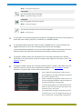
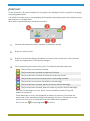
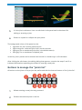
1
VERSION 5.1 USER’S MANUAL September 2015 Index WELCOME ...................................................................................................................................................... 3 LAUNCHER ............................................................................................................................................ 4 HSSJoints ............................................................................................................................................... 6 Main user interface................................................................................................................................... 6 Joints list ..................................................................................................................................................... 9 Buttons to manage the “Joints list” ................................................................................................... 10 Entering a new joint ............................................................................................................................ 11 Step 1: Type of joint ........................................................................................................................ 12 Step 2: Joint geometric data .......................................................................................................... 12 - T-Y Joint ................................................................................................................................. 13 - Unstiffened ”knee” Joint ...................................................................................................... 13 - X-W Joint ................................................................................................................................ 14 - K-N Joint................................................................................................................................. 14 - K-T Joint ................................................................................................................................. 15 Step 3: Member internal forces (Load combinations list) ......................................................... 16 Reports management and composition of drawings ........................................................................ 18 SBeton ................................................................................................................................................. 19 Main user interface................................................................................................................................. 19 Sections list .............................................................................................................................................. 22 Buttons to manage the “Sections list” .............................................................................................. 23 Entering a new cross-section ............................................................................................................ 25 Step 1: Type of cross-section ......................................................................................................... 25 Step 2: Cross-sectional data .......................................................................................................... 25 - Rectangular column ............................................................................................................ 27 - Rectangular beam................................................................................................................ 28 - Circular .................................................................................................................................. 28 - Generic .................................................................................................................................. 29 Buttons for the management of the entire cross-section (concrete and reinforcement) .................................................................................................................................................... 29 Buttons for the management of the cross-section polygons ........................................... 30 Buttons for the management of the reinforcing bars ....................................................... 31 Geometric requirements for the right definition of the generic cross-section .............. 31 Step 3: Internal forces (Load combinations list) ......................................................................... 32 1 Reports management and composition of drawings ........................................................................ 34 ProFire ................................................................................................................................................. 35 Main user interface................................................................................................................................. 35 Input data ................................................................................................................................................. 36 Results ...................................................................................................................................................... 36 Reports & Drawings.................................................................................................................................... 38 Reports ..................................................................................................................................................... 38 Drawings .................................................................................................................................................. 40 2D viewers ................................................................................................................................................... 43 3D viewers ................................................................................................................................................... 43 2 WELCOME Blue5Soft welcomes and invites you to discover its software for structural engineering. We have put our maximum effort and care to develop this software with the highest quality, so we hope will be to your liking. The interface of our programs has been designed and made so that the use of them is simple, intuitive and practical; hence all programs have many features in common. Remember that you are very important to us, so you can send us your suggestions and comments using the form at http://blue5soft.com/contact.html. Because we are continuously improving our software and even this manual, be sure to visit http://blue5soft.com/help/manuals.html to check if a new version of this manual is available. 3 LAUNCHER By running the shortcut created during the installation, it is shown a dialogue (launcher) with which runs each of our applications. This dialog is minimized in the notification area each time you launch one of the applications and restored by clicking on the icon or closing each of the launched applications. 1 Button through which you can select the default language for applications. Furthermore, each application can have its own different language than the launcher. By clicking this button, the following language selection dialog is displayed. 4 2 Button that launches a new session of HSSJoints program. When starting, the program will try to open the last opened project. If it does not exist on disk or it is open in another program session, the program will start with a new project. 3 Button that launches a new session of SBeton program. When starting, the program will try to open the last opened project. If it does not exist on disk or it is open in another program session, the program will start with a new project. 4 Button that launches a new session of ProFire program. 5 HSSJoints Hollow structural section joints Best-In-Class solution for the design of circular, square and rectangular hollow section joints. Includes a large number of design codes, data base of steel types & profiles from worldwide steel manufacturers. Generates excellent structural design reports along with detailed construction drawings. It is the most efficient software on the market for HSS welded connections. MAIN USER INTERFACE The following figure shows the main parts of the user interface. 1 Main menu. It contains all the options for managing the project. 2 Set of buttons that perform the most common options of the main menu. From left to right are: New Creates a new Project using the default settings. Menu: File/New 6 Open Opens an existing project. Menu: File/Open Save Saves the project in the specified file. Menu: File/Save Save as Saves the project in another file. Menu: File/Save as Project information Sets the project’s information. Menu: File/Project information Project notes Allows entering notes in the project. Menu: File/Project notes Report of all joints for the worst load combination Creates a report of all joints for the worst load combination of each one of them. Menu: File/Report of all joints for the worst load combination Drawing of all joints Creates drawings of all joint details. Menu: File/Drawing of all joints Profiles of the project Sets the profiles required in the project. Menu: Profiles/Profiles of the project Code Selects the code used in the project. Menu: Settings/Code Options Sets the options for reports. Menu: Settings/Reports/Options Text styles Sets the text styles used in reports. Menu: Settings/Reports/Text styles Layers Sets the layers for drawings. 7 Menu: Settings/Drawing/Layers Text styles Sets the text styles used in drawings. Menu: Settings/Drawing/Text styles Language Sets the language used in the program. Menu: Settings/Language Units Sets the units and their precisions used in the project. Menu: Settings/Units 3 It is the part of the main interface intended for manage all the joints of the project to which we have called "Joints list" and which it is detailed below. 4 It is the panel which we have called "Load combinations list" and it is where the applied internal forces to the currently selected joint are managed. Load combinations applied to a joint can be modified both in this panel and in the panel shown in the last step of the wizard for editing / entering of a joint. 5 2D graphic viewer where the full detail of the currently selected joint is drawn. Information on use and the common context menu options are shown in the "2D viewers” section. 6 3D graphic viewer where the currently selected joint is shown. Information on use and the common context menu options are shown in the "3D viewers” section. However, the particular context menu options are: Show / Hide the representation of the internal forces applied in the load combination selected in the "Load combination list". Enable / Disable cutting planes XZ and YZ in such a way as displayed members and their welds can be sectioned by these cutting planes. To move cutting planes, click with the left mouse button on the icon with scissors and move in the direction of the Y and X axis. If you hold down the right mouse button on the icon with scissor, you can change the position of the icon within the corresponding cutting plane. 8 JOINTS LIST In the "Joints list", all joints introduced in the project are displayed and it is possible to manage everything about them. It is divided into two parts, a top displaying all the panels representing each joint and a bottom with buttons to manage them. Each joint is represented by a panel that contains: 1 Scheme that shows the joint's elevation to identify it quickly. 2 Button to edit the joint. 3 Button to launch the dialog that allows you enter notes on the joint. If the joint has notes, the appearance of the button changes. 4 Icon representing the status of the joint. The different possible status are: The joint has not yet been checked. The joint has been checked and passes all checks. The joint has been checked and does not meet any checks. The joint has some errors that prevent it from being checked. The joint has not yet been checked but has warnings. The joint has been checked, passes all checks and has warnings. The joint has been checked, does not meet any checks and has warnings. If a joint has warnings or errors, these can be consulted in both 2D and 3D viewers and reports. These warnings or errors are displayed in viewers by means of icons that are positioned on the members having such warnings or errors. Placing the mouse cursor over the icons, a tooltip with the informational text appears. Such icons are: for warnings and for errors. 9 5 It is the joint's reference. User can edit both in this panel and in the wizard for editing or entering a joint. 6 Button to expand or collapse the joint panel. The background colour of this panel can be: Light blue for the currently selected joint. Light orange for a selected joint that is not the current. Light grey for an unselected joint (this is the default status). Dark grey for an unselected collapsed joint. In this list, joint's panels can be selected and sorted in a similar way to a file browser. After clicking the edit button, the editing dialog that appears, contains the steps 2 and 3 as indicated below when explaining the wizard to entering a new joint. Buttons to manage the “Joints list” All actions on the joints of the project are performed with the bottom buttons of the “Joints list”. 1 Allows entering a new joint using a wizard. 2 Deletes the selected joints in the list. 10 3 Creates new joints copying the selected joints in the list. 4 Collapses the panels of all joints in the list. 5 Expands the panels of all joints in the list. 6 Checks the selected joints in the list. 7 Checks all joints in the list. 8 Creates a report with the selected joints in the list. If from among those selected, there is a joint that has not yet been checked, program asks to the user about to check it before generating the report. For the checked joints, resistance checks are those corresponding for the worst load combination of each one. 9 Creates a report with all joints in the list. If from among those selected, there is a joint that has not yet been checked, program asks to the user about to check it before generating the report. For the checked joints, resistance checks are those corresponding for the worst load combination of each one. 10 Creates drawings with the details of the selected joints in the list. For it, launches a dialog where user can set up how to create these drawings. If from among those selected, there is a joint that has not yet been checked, program asks to the user about to check it before generating the drawings. Furthermore, if there are joints that do not check, user decides whether to continue showing the drawings or not. 11 In a similar way to the previous button, this button creates drawings with the details of all joints in the list. Entering a new joint By clicking the button for entering a new joint, program shows a wizard that contains the following three steps: 1. Type of joint 2. Joint geometric data 3. Member internal forces 11 To go to the next step, click the "Next" triangular button (on the right side of the dialog) and to go to the previous step, click the "Back" triangular button (on the left side of the dialog). Step 1: Type of joint In this step, it is selected the desired type of joint. It is allowed to enter joints according to two groups, the first one with circular hollow section (CHS) chord and the second with rectangular (RHS) or square (SHS) hollow section chord. In the case of CHS chord, braces must also be CHS. For RHS or SHS chord, braces may be CHS, RHS or SHS. After clicking on the image that represents the geometry of the new joint, it is possible to go to the next step. Step 2: Joint geometric data Depending on the type of joint that has been selected in the previous step, in this step it must be entered the geometric data needed to define the joint. Here are the geometric data to be entered depending on the selected type of joint. 12 - T-Y Joint The brace angle is measured with respect to the right stretch of the chord. - Unstiffened ”knee” Joint The angle to be entered is the included angle between the cranked-chord and the chord. It requires that the interior dimensions are the same for both members, but not the outer dimensions. 13 - X-W Joint Both the top brace angle and the bottom brace angle are measured with respect to the right stretch of the chord. - K-N Joint The left brace angle is measured with respect to the left stretch of the chord and the right brace angle is measured with respect to the right stretch of the chord. Relative position between both braces can be established in three ways: By the eccentricity (e) between the crossing point of the two braces axis and the direction of the chord. Is positive if the crossing point is located outwards of the braces and negative if it is located on the same side of the braces. 14 By the gap (g) or spacing between the walls of both braces. By the overlapping length (Ov) between both braces. - K-T Joint The left brace angle is measured with respect to the left stretch of the chord and the vertical and right brace angles are measured with respect to the right stretch of the chord. It is not required that vertical be perpendicular to the chord. Relative position between left brace, vertical and right brace, can be established two by two in the same way as for K-N joints. In the data grid shown on the joint panel data, for each member, it is mandatory to enter the profile, steel and whether the profile is tumbled or not (if proceed). Note that in this step, you can use profiles that you already have previously entered in the profiles of the project or, here you can add new profiles to the profiles of the project too. The following figure shows a profile that is tumbled and the other one is not. 15 Width: 100.0 Height: 150.0 Tumbled Not tumbled Please click here to learn more about the profiles of the project. Step 3: Member internal forces (Load combinations list) In this final step, it is entered the applied internal forces in braces and in the chord before the joint (left) and after the joint (right). Please click here to get information about sign convention. Please click here to get information about using clipboard to paste the applied internal forces. Controls for managing the member internal forces are: 1 Button to enter a new load combination with default data. 2 Button to delete the selected load combinations in the list. 3 Button to delete all load combinations in the list. 4 Button to copy the selected load combinations in the list. 16 5 Option to set whether or not to take into account shear forces to check the joint. 6 Option to set whether or not to take into account bending moments to check the joint. In the above figure, load combination N# 80 is considered the current load combination for the current joint and it is whose internal forces are represented in the 3D viewer. "Load combinations list" buttons change when the list is displayed in the main interface. Three new buttons appear: 7 Creates a report of the current joint in which the resistance to the selected load combinations in the list is checked. 8 Creates a report of the current joint in which the resistance to all load combinations in the list is checked. Note that if the number of load combinations is high, the created report will have a large number of pages. 9 Creates a report of the current joint in which the resistance to the worst load combination is checked, i.e., the one that produces the maximum use. The header columns of the applied internal forces have a context menu that allows to apply two operations to all values of the column: Multiply by a factor Add a value These options are very useful and allow to consider cases such as, after pasting internal forces from the clipboard, the user wants to: 17 Reverse the sign of applied internal forces enter a multiplier of -1. Convert units enter a multiplier factor equal to the conversion factor. REPORTS MANAGEMENT AND COMPOSITION OF DRAWINGS See section “Reports & Drawings”. 18 SBeton Analysis of reinforced concrete sections Advanced solution for the design of reinforced concrete cross-section of any shape with any reinforcement layout. Produces comprehensive design reports for various international design codes and high quality construction drawings. Calculates collapse stages under different assumptions for axial and bending moments and also calculates the strength interaction volume. One of the most powerful in its scope, optimized to perform very rigorous analyses in negligible times. MAIN USER INTERFACE The following figure shows the main parts of the user interface. 1 Main menu. It contains all the options for managing the project. 2 Set of buttons that perform the most common options of the main menu. From left to right are: New Creates a new project using the default settings. 19 Menu: File/New Open Opens an existing project. Menu: File/Open Save Saves the project in the specified file. Menu: File/Save Save as Saves the project in another file. Menu: File/Save as Project information Sets the project’s information. Menu: File/Project information Project notes Allows entering notes in the project. Menu: File/Project notes Report of all cross-sections for the worst load combination Creates a report of all cross-sections for the worst load combination of each one of them. Menu: File/Report of all cross-sections for the worst load combination Drawing of all cross-sections Creates drawings of all cross-sections. Menu: File/Drawing of all cross-sections Concrete Sets the concrete required in the project. Menu: Materials/Concrete Reinforcement Sets the reinforcing steels required in the project. Menu: Materials/Reinforcement Code Selects the code used in the project. Menu: Settings/Code Options Sets the options for reports. Menu: Settings/Reports/Options 20 Text styles Sets the text styles used in reports. Menu: Settings/Reports/Text styles Layers Sets the layers for drawings. Menu: Settings/Drawing/Layers Text styles Sets the text styles used in drawings. Menu: Settings/Drawing/Text styles Language Sets the language used in the program. Menu: Settings/Language Units Sets the units and their precisions used in the project. Menu: Settings/Units 3 It is the part of the main interface intended for manage all the cross-sections of the project to which we have called "Sections list" and which it is detailed below. 4 It is the panel which we have called "Load combinations list" and it is where the applied internal forces to the currently selected cross-section are managed. Load combinations applied to a cross-section can be modified both in this panel and in the panel shown in the last step of the wizard for editing / entering of a crosssection. 5 2D graphic viewer where the full detail of the currently selected cross-section is drawn. Information on use and the common context menu options are shown in the "2D viewers” section. 6 3D graphic viewer where the currently selected joint is shown. Information on use and the common context menu options are shown in the "3D viewers” section. However, the particular context menu options that correspond to the load combination selected in the "Load combinations list" are: 21 Show / Hide the representation of the internal forces applied in the load combination selected in the "Load combination list". Show / Hide concrete stresses. Show / Hide the deformed state of the crosssection. Show / Hide straight lines of constant strain that separate the different ranges of concrete's behaviour. Show / Hide the internal results in concrete, in the compressed reinforcement and in the tensile reinforcement. 7 3D graphic viewer that shows the strength interaction volume of the currently selected cross-section, if it has been calculated. Information on use and the common context menu options are shown in the "3D viewers” section. However, the particular context menu options are: Show / Hide the solid fill of the strength interaction volume. Consult the information at the points which has been discretized the strength interaction volume. The underlined option is available only for concrete codes that distinguish between nominal strength and design strength. Allows to show / hide the nominal strength interaction volume. This viewer has a vertical scroll bar on the left side that allows changing the aspect ratio of the strength interaction volume. SECTIONS LIST In the "Section list", all cross-sections introduced in the project are displayed and it is possible to manage everything about them. It is divided into two parts, a top displaying all the panels representing each cross-sections and a bottom with buttons to manage them. Each cross-section is represented by a panel that contains: 22 1 Scheme that shows the cross-section. 2 Button to edit the cross-section. 3 Button to launch the dialog that allows you enter notes on the cross-section. If the cross-section has notes, the appearance of the button changes. 4 Icon representing the status of the cross-section. The different possible status are: The cross-section has not yet been checked. The cross-section has been checked and passes all checks. The cross-section has been checked and does not meet any checks. 5 It is the cross-section’s reference. User can edit both in this panel and in the wizard for editing or entering a cross-section. 6 Button to expand or collapse the cross-section panel. The background colour of this panel can be: Light blue for the currently selected cross-section. Light orange for a selected cross-section that is not the current. Light grey for an unselected cross-section (this is the default status). Dark grey for an unselected collapsed cross-section. In this list, cross-section’s panels can be selected and sorted in a similar way to a file browser. After clicking the edit button, the editing dialog that appears contains the steps 2 and 3 as indicated below when explaining the wizard to entering a new cross-section. Buttons to manage the “Sections list” All actions on the cross-sections of the project are performed with the bottom buttons of the “Sections list”. 23 1 Allows entering a new cross-section using a wizard. 2 Deletes the selected cross-sections in the list. 3 Creates new cross-sections copying the selected cross-sections in the list. 4 Collapses the panels of all cross.-sections in the list. 5 Expands the panels of all cross.-sections in the list. 6 Checks the selected cross-sections in the list. 7 Checks all cross-sections in the list. 8 Creates a report with the selected cross-sections in the list. If from among those selected, there is a cross-section that has not yet been checked, program asks to the user about to check it before generating the report. For the checked cross-sections, resistance checks are those corresponding for the worst load combination of each one. 9 Creates a report with all cross-sections in the list. If from among those selected, there is a cross-section that has not yet been checked, program asks to the user about to check it before generating the report. For the checked cross-sections, resistance checks are those corresponding for the worst load combination of each one. 10 Creates drawings with the details of the selected cross-sections in the list. For it, launches a dialog where user can set up how to create these drawings. If from among those selected, there is a cross-section that has not yet been checked, 24 program asks to the user about to check it before generating the drawings. Furthermore, if there are cross-sections that do not check, user decides whether to continue showing the drawings or not. 11 In a similar way to the previous button, this button creates drawings with the details of all cross-sections in the list. Entering a new cross-section By clicking the button for entering a new cross-section, program shows a wizard that contains the following three steps: 1. Type of cross-section 2. Cross-sectional data 3. Cross-sectional forces To go to the next step, click the "Next" triangular button (on the right side of the dialog) and to go to the previous step, click the "Back" triangular button (on the left side of the dialog). Step 1: Type of cross-section In this step, it is selected the desired type of cross-section. It is allowed to enter cross-sections according to two groups, the first one composed by parameterized cross-sections and the second formed by the generic cross-section. After clicking on the image that represents the geometry of the new cross-section, it is possible to go to the next step. Step 2: Cross-sectional data Depending on the type of cross-section that has been selected in the previous step, in this step it must be entered the data needed to fully define both the geometry and the reinforcement of the cross-section. 25 The editing panels of the three parameterized cross-sections have a button that allows to convert the cross-section into a generic one to make the changes that the user wants. Both the concrete and the reinforcing steel of the cross-section can be defined in this step (which will be added as project materials) however, it is recommended to define them before entering cross-sections because in doing so, the definition of a new cross-section is sped up. Buttons shown in the following figure allows to user to edit the concretes and the reinforcing steels of the project. In this step, the default concrete and reinforcing steel are those that are most frequently used in the project. If materials defined in the project are not compatible with the selected concrete code, the program does not offer any default material. If reinforcing steel is changed, the program automatically searches the diameter of the reinforcement that is closest to the previously assigned. For all types of cross-sections, the program allows to indicate whether to ignore the concrete that is displaced by the reinforcement or not. To do this, use the following check box: If this option is checked, the net area of concrete is considered to be equal to the gross area (this is what is commonly used). We recommend unchecking this option for strongly reinforced crosssections. According to the selected concrete code, it is possible that the following button appears, that allows to specify the necessary attributes to check the cross-section. ACI 318M-08, ACI 318M-11 and CIRSOC 201:2005 26 NTE E.060:2009 CAN/CSA 23.3-04 Program considers that the cross-section is defined in a Cartesian plane whose abscissa is the Y axis and the ordinate is the Z axis. Here are the data to be entered depending on the selected type of cross-section. - Rectangular column 27 - Rectangular beam - Circular 28 - Generic This is the cross-section that allows the highest possible setting. It offers a set of tools that simplify all the management relating to the entering of the concrete geometry and the reinforcement. The generic cross-section can contain holes and there is no limit on their number. Buttons for the management of the entire cross-section (concrete and reinforcement) These buttons allow to perform actions on the entire cross-section: 1 Move the cross-section such that the origin (YZ) coincides with the centre of gravity of the concrete section. 2 Apply a displacement by the two components in the YZ plane. 3 Rotate the cross-section about a point in the YZ plane. 4 Scale the cross-section about a point in the YZ plane. 29 5 Make horizontal or vertical symmetry of the cross-section with respect to a coordinate in the Z axis or Y respectively. 6 Import a cross-section from a DXF™ file. Are taken into account closed polylines and circles contained in any XY plane. Polylines and circles with a diameter greater than 75 mm are used to define the concrete cross-section. The polyline with the largest area is considered as the external polygon of the cross-section and the remaining polylines are considered as holes. Circles with diameter less than or equal to 75 mm are considered as bars and the program searches for the nearest diameter within the diameter series of the default steel for new bars. If default steel is not defined, bars are not imported. 7 Export the current cross-section to a DXF™ file. This button is enabled only if the cross-section is correctly defined. Buttons for the management of the cross-section polygons The following buttons are available for both the external polygon as for holes: 1 Creates a rectangular polygon. 2 Create an n-sided regular polygon inscribed in a circumference. 3 Creates a T-shaped polygon. 4 Creates an L-shaped polygon. 5 Creates a Z-shaped polygon. 30 By using the above buttons, the previously entered vertexes are removed and new vertexes are added to create the corresponding polygon. 6 Allows to apply a displacement to each vertex by the two components in the YZ plane. 7 Allows to rotate the polygon about a point in the YZ plane. 8 Allows to scale the polygon about a point in the YZ plane. 9 Make horizontal or vertical symmetry of the polygon with respect to a coordinate in the Z axis or Y respectively. Vertexes with repeated coordinates or aligned with two other neighbouring vertexes are ignored. Buttons for the management of the reinforcing bars For each of the entered coordinates of the bars’ centre, it is allowed a similar management of the polygon's vertexes. To do this, the following buttons, which act over all bars, are available: 1 Allows to apply a displacement to each centre of bar by the two components in the YZ plane. 2 Allows to rotate each centre of bar about a point in the YZ plane. 3 Allows to scale each centre of bar about a point in the YZ plane. 4 Make horizontal or vertical symmetry of each centre of bar with respect to a coordinate in the Z axis or Y respectively. Geometric requirements for the right definition of the generic cross-section The following requirements have to be met to consider that a generic cross-section is correctly entered: Each polygon must contain at least three non-aligned and non-coincident vertexes. Sides of any polygon cannot cross each other. 31 Polygons cannot cross each other and cannot have vertexes located at the perimeter of other. Vertexes of holes should not be located neither the perimeter nor outside the external polygon. Bars should not be located neither inside a hole nor outside the external polygon. There must be at least one bar correctly defined. Main dimensions cannot exceed 100 meters and cannot be less than 5 centimetres. Holes should have dimensions between 1.5 centimetres and 50 meters. Cross-section must be correctly defined for passing to the last step of the wizard. Step 3: Internal forces (Load combinations list) In this final step, it is entered the applied internal forces to be checked. The entered applied internal forces are those obtained from the load combinations set according to the selected concrete code. For most codes, these applied internal forces are coming from factored load combinations. It is important to note that the applied internal forces you enter are those that will be checked, therefore you should consider buckling, minimum eccentricities, minimum forces, concrete capacity design or any other phenomenon that makes internal forces that the program has to check could be different than the given from an analysis model. Please click here to get information about sign convention. Please click here to get information about using clipboard to paste the applied internal forces. Controls for managing the internal forces are: 32 1 Button to enter a new load combination with default data. 2 Button to delete the selected load combinations in the list. 3 Button to delete all load combinations in the list. 4 Button to copy the selected load combinations in the list. 5 Option to set whether or not to get the resistance of the cross-section for each load combination according to a way to collapse. In the above figure, load combination N# 485 is considered the current load combination for the current cross-section and it is whose internal forces are represented in the central 3D viewer. "Load combinations list" buttons change when the list is displayed in the main interface. Five buttons appear and will be enabled if the cross-section has been checked. 6 Calculates the strength interaction volume and represents it in the 3D viewer on the right. Once calculated the strength interaction volume, this button is disabled and the next button is enabled. 7 Shows the applied internal forces and the resistant ones (if they are calculated) in the 3D viewer on the right. If the selected concrete code distinguishes between persistent or transient and accidental situations, internal forces are displayed in the corresponding strength interaction volume. 8 Allows to analyse the moment-curvature diagram of the current cross-section. 9 Allows to analyse the 2D resistance diagrams of the current cross-section (meridians and parallels of the strength interaction volume). 10 Creates a report of the current cross-section in which the resistance to the selected load combinations in the list is checked. 11 Creates a report of the current cross-section in which the resistance to all load combinations in the list is checked. Note that if the number of load combinations is 33 high, the created report will have a large number of pages. 12 Creates a report of the current cross-section in which the resistance to the worst load combination is checked, i.e., the one that produces the maximum use. The header columns of the applied internal forces have a similar context menu than the explained at the "Load combinations list" in HSSJoints except for the columns of applied bending moments, where two options are added: - Swap the bending moments such a way that bending moment about Y axis becomes the bending moment about Z axis and vice versa.. - Rotate the applied bending moments by an angle that the user enters. REPORTS MANAGEMENT AND COMPOSITION OF DRAWINGS See section “Reports & Drawings”. 34 ProFire Analysis of I-H shaped profiles under fire situation This program analyses the heating evolution of I-H shaped steel profiles under fire situation (protected and unprotected profiles). Allows to use typical or user-defined fire protections. The user sets the sides which are exposed to fire. Includes a large number of I-H shaped sections from various countries. MAIN USER INTERFACE The following figure shows the main parts of the user interface. 1 Main menu. 2 Set of buttons that perform the most common options of the main menu. From left to right are: Code Selects the code used in the project. Menu: Settings/Code 35 Language Sets the language used in the program. Menu: Settings/Language Units Sets the units and their precisions used in the project. Menu: Settings/Units 3 It is the part of the main interface intended for data entry. 4 Panel that contains the 2D graphic viewer that represents the profile under study, its fire protection (if does) and a data grid with the profile's properties. 5 It is the part of the main interface where calculations are performed. 6 Graph showing the evolution of both the gas and the profile's temperature from the beginning of the fire. Moving the mouse cursor over both graphs, it is shown the pair of time-temperature values. By pressing the "Control" key, label justification is changed. INPUT DATA The input data are: Information about time of fire exposure (according to the code or user-defined). Sides exposed to fire. The profile to be analysed. Indication whether the profile has fire protection or not. In the case that the profile is protected, it can choose from different typified protections or use a fire protection with user-defined data. RESULTS Calculation is performed by pressing the button or “F5” key. If the profile is protected, two types of calculations can be performed Calculate the temperature reached by the profile in the required resistance time for a given fire protection thickness. 36 Calculate the minimum required fire protection thickness for a user-defined temperature reached by the profile for the required resistance time. If the profile is not protected, calculation consists in determine the temperature reached by the profile in the required resistance time. 37 Reports & Drawings In this section it is explained the common aspects to all programs that display reports and create drawings. REPORTS The dialog for previewing reports has the following set of available controls: 1 Viewer that previews the report. 2 Button that displays the following dialog for page setting (printer, paper tray, orientation and margins). 38 3 Navigation through pages. Options from left to right are: 4 Zoom settings. Options from left to right are: 5 Display mode. Options from left to right are: 6 Document output device. Options from left to right are: 7 Vertical scroll bar. Both the scroll bar and the mouse wheel allow to scroll up or down on the entire report. Go to the first page Go to previous page Go to next page Go to the last page Go to a given page Zoom out Zoom in Zoom percentage Actual size Page width Full page Continuous among pages One page Two pages Output to printer Export to the ”.docx” file format 39 DRAWINGS The dialog for drawings composition has the following set of available controls: 1 Viewer that previews the composed drawings by the program using the user's settings. 2 Button to configure the scales used in drawings. Programs allow two ways to set the scales: Automatic: for each element to be drawn, the program determines what is the scale that best fits it minimum dimension to the size specified in the surrounded text box. Scales that programs test are those used in the "single scale" mode. Single scale: all elements are drawn with the same scale. 40 3 Composition of drawings. This button displays a dialog where the user can select whether to compose drawings using papers or not. If wants to compose using papers, the program allows to set the papers to be used, margins, reserve space for a title box and where to locate it. 4 Setting drawing layers as a CAD program. 5 Output the composed drawings to printer or plotter. If papers are used, program prints one by one each drawing. It is possible to skip printing of a certain drawing by following the program instructions. To select whether to print drawings in black and white or colour, use the context menu of the printing viewer: 41 6 Export all created drawings to a single DXF™ file (version 2004). RGB objects colours are exported to the closest ACI colour index. 42 2D viewers 2D viewers are used as follows: With the mouse wheel zooms in or out the view. The view is moved by holding down and moving the middle mouse button. Fit view by double-clicking the middle mouse button. By clicking the right mouse button, the context menu is activated and shows the following common options for all 2D viewers: Change the background colour of the viewer. Show / Hide the lines thickness. If hide is chosen, the viewer shows all lines with a thickness of 1 pixel. Zoom into a specific area through a selection window. Fit the zoom such that the content of the viewer is fully visible. 3D viewers 3D viewers are used as follows: With the mouse wheel zooms in or out the camera with respect to the cursor location on the viewer. The camera is moved by holding down and moving the middle mouse button. Fit view by double-clicking the middle mouse button. By clicking the right mouse button, the context menu is activated and shows the following common options for all 3D viewers: Copy to the clipboard the current image of the viewer. Change the background colour of the viewer. Show / Hide the icon that represents the centre of rotation ( ). The centre of rotation is the point about which the camera rotates. Change the position of the centre of rotation. This action can also be performed by pressing the "Control" + "R" keys. By selecting this option, click the mouse over a point on the surface of any object and it will become the new centre of rotation. Fit the zoom such that the content of the viewer is fully visible. 43