1
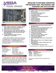
PCM-36E06
PC/104 Advanced Communications Module
User Manual
Rev 0.2
+DISCLAIMER ................................................................................................................ 3
INTRODUCTION............................................................................................................. 4
GPS MODULE ............................................................................................................... 4
DIAL-UP MODEM MODULE ...................................................................................... 5
CELL MODEM MODULE ............................................................................................ 5
SPECIFICATIONS........................................................................................................... 5
UARTS ........................................................................................................................... 5
GPS MODULE ............................................................................................................... 5
CELL MODEM MODULE ............................................................................................ 6
DIAL-UP MODEM MODULE ...................................................................................... 6
MECHANICAL AND ENVIRONMENTAL................................................................. 6
CONFIGURATION.......................................................................................................... 6
SETTING THE UART I/O ADDRESSES ..................................................................... 6
IRQ SELECTION........................................................................................................... 7
CELL MODEM CONFIGURATION ............................................................................ 7
CONNECTORS ................................................................................................................ 8
HDR1: CONFIGURATION ........................................................................................... 8
HDR2: UART 1, RS-232 PORT..................................................................................... 8
HDR3: DIAL-UP MODEM SPEAKER......................................................................... 8
JK1: PHONE LINE JACK.............................................................................................. 8
CONTROL REGISTER................................................................................................... 9
2
PRELIMINARY
SUBJECT TO CHANGE WITHOUT NOTICE
DISCLAIMER
EMAC Inc. does not assume any liability arising out of the application or use of
any of its products or designs. Products designed or distributed by EMAC Inc.
are not intended for, or authorized to be used in, applications such as life support
systems or for any other use in which the failure of the product could potentially
result in personal injury, death or property damage.
If EMAC Inc. products are used in any of the aforementioned unintended or
unauthorized applications, Purchaser shall indemnify and hold EMAC Inc. and its
employees and officers harmless against all claims, costs, damages, expenses,
and attorney fees that may directly or indirectly arise out of any claim of personal
injury, death or property damage associated with such unintended or
unauthorized use, even if it is alleged that EMAC Inc. was negligent in the design
or manufacture of the product.
EMAC Inc. reserves the right to make changes to any products with the intent to
improve overall quality, without further notification.
3
PRELIMINARY
SUBJECT TO CHANGE WITHOUT NOTICE
INTRODUCTION
The PCM-36E06 is a PC/104 Advanced Communication Module with the following
features:
8-Bit PC/104 card with 16-Bit pass-through.
Dual standard 16550 on-board UARTs with address & IRQ jumper selection.
Solid and proven Trimble(r) 12-channel GPS engine, provides accurate
performance, and is a Cost-effective GPS solution
GPRS/GSM/PCS Cell Modem with internal TCP/IP stack with AT command
control.
GSM Tri Band 900/1800/1900 MHz International Cell Modem.
Provision for Multi-Tech Socket Modem products, including 2400 to 56K baud
dial-up modems, Bluetooth Modules with planned support for future
communication technologies.
Additional RS232 Serial Port.
Single 5 Volt supply Operation.
Compatible with virtually all Operating Systems including Linux, WinCE,
WinXP and DOS.
The combination of GPS and a GPRS/GSM/PCS modem on a single PC/104 module is
extremely useful. Any GPS application that needs to communicate will by nature require
a wireless connection. The PCM-36E06, GPS/GPRS combination is an unprecedented
value when both GPS and a Cell Modem are required.
The PCM-36E06 uses a 16550 compatible dual UART as the interface to communicate to
the GPS, Cell Modem and Dial-Up Modem. Jumpers allow each UART to be
individually mapped to different I/O locations and there are also jumpers to select the
desired interrupt for each UART. Different component populations allow UART channel
1 to be configured for RS-232 Serial port or GPS communication, and channel 2 can be
configured as a Dial-Up or GPRS/GSM/PCS Fax/Modem. There are many combinations
possible, but not all may be available off-the-shelf. See www.emacinc.com for listings of
the currently supported off-the-shelf combinations or contact [email protected] to
discuss a custom combination.
Following are summaries of the different modules.
GPS MODULE
The GPS engine used is the Trimble® Lassen iQ, a 12-channel parallel tracking engine
which is ideally suited for embedded applications. The GPS uses a sophisticated satellite
technology to locate and track any location in the world, in real-time. The Lassen iQ GPS
receiver outputs a complete position, velocity, and time (PVT) solution in either NMEA
version 3.0 ASCII or Trimble TSIP binary protocol. A Pulse-Per-Second (PPS) signal is
available for very accurate timing and synchronization applications. This signal can be
used to generate a processor interrupt if required. See the Trimble® Lassen iQ PDF for
more details.
4
PRELIMINARY
SUBJECT TO CHANGE WITHOUT NOTICE
DIAL-UP MODEM MODULE
The Dial-Up Fax/Modem utilizes a standard Multi-Tech embedded socket modem
module. These modem modules come in a variety of speeds from 2400 baud to 56K baud
and can be easily exchanged. There are also other modules available from Multi-Tech
that can plug into this modem socket, including a Bluetooth module. They have plans to
support other emerging communication technologies as well. See the Multi-Tech
SocketModem PDFs for more details.
CELL MODEM MODULE
The Telit GPRS/GSM/PCS Fax/Modem is the ideal solution for remote wireless data
communications. It supports 900, 1800, 1900 Mhz bands allowing it to work
internationally at packed data rates of up to 85.6Kbps. This GPRS modem also provides
an internal TCP/IP stack allowing lower-end operating systems such as DOS to
communicate over the Internet. Modem control is handled through the simple and
familiar AT command set eliminating the need for custom drivers. See the Telit GM862PCS PDF for more details
SPECIFICATIONS
UARTS
IC: National Semiconductor 16550 compatible PC16552 Dual UART or
equivalent.
UART Channel 1: RS232 Serial Port or GPS MODULE
UART Channel 2: Dial-Up Modem Module or GPRS/GSM Cell Modem.
Baud Rate: 50 ~ 115,200 bps.
Interrupts: IRQ 3,4,5,6,7,9,10,11,12, or 15, individually selectable or shared.
I/O Addressing: I/O address range for each channel is individually jumper
selectable from 200 to 3F8 Hex.
GPS MODULE
Control Chipset: Trimble(r) Colossus RF ASIC & IO-TS DSP, 32-Bit RISC
CPU.
Receiving Channel: 8-channel, continuous tracking receiver with 32 correlators
Receiving Frequency: L1 (1575.42 MHz), C/A code.
Protocols: TSIP, TAIP & NMEA.
Navigation Update Rate: 1 Hz (1 second).
Time to First Fix: Cold start 84 seconds, Warm start 42 seconds, Hot Start 13
seconds.
Antenna: Trimble P/N 39265-02 with 15' of cable. GPS has antenna short-circuit
detection and protection.
5
PRELIMINARY
SUBJECT TO CHANGE WITHOUT NOTICE
CELL MODEM MODULE
Control Module: Telit GM862-PCS
Output Frequency: GSM - 900 Mhz, DCS - 1800 Mhz, PCS-1900 MHz.
Output Power: GSM - 2 Watt Peak, DCS - 1 Watt Peak, PCS-1 Watt Peak.
Compliance: GPRS class B -class 10. GSM Phase 2/2+.
Modem Control: AT Command set with ITU, GSM, GPRS, Telit extensions.
Sensitivity: Better than -102 dBm in normal operating conditions.
Data Speed: CSD up to 14.4Kbps. Packed Data up to 85.6Kbps.
Clock: Real-Time Clock/Calendar with Alarm functionality.
Antenna: 50 Ohm, 1.6" high Helical Stub with a cable length of 9".
DIAL-UP MODEM MODULE
Data Modem: ITU-T V.92/V.90/56K, V.34/33.6K, V.32bis/14.4K, V.22bis/2400
baud.
Fax Modem: ITU-T V.17, V.29, V.27, V.21.
Approvals: Global
Certifications: UL1950, CSA 950, EN 60950, AS 3260, CCC, FCC Part 15.
Modem Control: AT Command set.
Error Correction: V.42 LAPM, MNP 2-4.
Data Compression: V.42bis, MNP Class 5.
Modem Speed: 56 Kbps maximum.
Fax Speed: 14.4 Kbps maximum..
MECHANICAL AND ENVIRONMENTAL
Power Requirements: 5 V ± 5 %, ripples within 50 mV p-p
Power Consumption: + 5 V @ 300 mA (typical)
Operating Temperature: 0° ~ 60°C (32° ~ 140°F)
Operating Humidity: 0% to 95% relative humidity, non-condensing
Board Dimensions: 96 mm x 90 mm (3.77" x 3.54") (L x W)
Weight: approximately102 g (0.224 lbs.)
CONFIGURATION
SETTING THE UART I/O ADDRESSES
There are two jumper blocks to set the I/O addresses for the UARTS and the control
register:
JB4
JB5
UART 1 (RS232 Serial port or GPS )
UART 2 (Dial-Up or GPRS/GSM/PCS Fax/Modem)
Each jumper block shows a hexadecimal weighted value to the left of it. To determine
the address, add the weighted value of each shunt present and add 200 hex to the total.
The following table shows the jumper settings for common UART addresses.
6
PRELIMINARY
SUBJECT TO CHANGE WITHOUT NOTICE
008
010
3F8
JJ
JJ
ADDRESSES
3E8
2F8
JJ
JJ
JJ
2E8
JJ
020
JJ
JJ
JJ
JJ
040
JJ
JJ
JJ
JJ
080
100
JJ
JJ
JJ
JJ
JJ
JJ
For example, if you look at the 2E8 column, the values added would be
(008+020+040+080)+200=2E8.
IRQ SELECTION
There are three jumper blocks for selecting IRQs:
JB1
JB2
JB3
UART 1 (RS232 Serial port or GPS )
UART 2 (Dial-Up or GPRS/GSM/PCS Fax/Modem)
GPS 1Hz timing signal (PPS). See GPS Module for more details.
Only one shunt per jumper block should be used.
CELL MODEM CONFIGURATION
A SIM must be obtained from your cell service provider and inserted in the cell modem
module as shown on the sticker on the module
If the cell modem is used for incoming and outgoing server type data exchange
communication, an Internet type APN should be requested which provides a Public
incoming and outgoing IP address.
The cell modem should be queried to make sure it is configured with the correct
frequency band for its region. The code for each band is shown below.
BAND CODE
0
1
FREQUENCY
DCS 1800 MHz
PCS 1900 MHz
REGION
EUROPE
U.S.
7
PRELIMINARY
SUBJECT TO CHANGE WITHOUT NOTICE
The command AT#BND? will return the current band code configuration. If this is not
the desired band, the command AT#BND=0 or AT#BND=1 can be used to set it. This is
a non-volatile configuration.
CONNECTORS
HDR1: CONFIGURATION
This should not be used. It is only used for configuration during manufacturing.
HDR2: UART 1, RS-232 PORT
The optional RS-232 serial port connector has the following pin assignments.
HDR2 (UART 1)
(NOT USED)
RECEIVE
TRANSMIT
(NOT USED)
GROUND
1
3
5
7
9
2
4
6
8
10
(NOT USED)
RTS
CTS
(NOT USED)
(NOT USED)
The pin assignments for the DB9 adaptor that plugs into this header are related,
but different.
DB9 PIN #
1
2
3
4
5
6
7
8
9
DESCRIPTION
(NOT USED)
RECEIVE
TRANSMIT
(NOT USED)
GROUND
(NOT USED)
RTS
CTS
(NOT USED)
HDR3: DIAL-UP MODEM SPEAKER
If the dial-up modem is installed, HDR3 allows connecting an external speaker for
monitoring the dial-up modem’s call progress.
1- SPEAKER OUTPUT
2- GROUND
JK1: PHONE LINE JACK
If the dial-up modem is installed, this provides a standard jack for connecting the modem
to the phone line.
8
PRELIMINARY
SUBJECT TO CHANGE WITHOUT NOTICE
CONTROL REGISTER
The control register implemented is a single register but it is accessible from two separate
I/O addresses. The register addresses are the UART 1 and UART 2 base addresses +7.
For example, if UART 1 was at 3F8 and UART 2 was at 2E8, the control register would
be accessible at both 3FF (3F8+7) and 2EF (2E8+7).
The register is defined as follows:
BIT
0
1
2
3
4
5
6
7
NOTES:
(1)
(2)
RD
WR(1)
FUNCTION
Read state of the UART 1 (RS-232 or GPS Module) Interrupt line
Read state of the UART 2 (Dial-Up or Cell Modem) Interrupt line
Read state of the GPS Pulse-Per-Second (PPS) output line
Read state of the ISA reset-in line
Read state of the Cell Modem PWRCTL line (reads 1if the Cell Modem is on)
Read or Write the state of the active-low reset out (resets the Dial-Up Modem)
Read or Write the state of the output port(2) that drives the Cell Modem
ON/OFF toggle input.
Not used. Reads 0.
Writing to a bit without write capability has no effect.
The output of this port is inverted before being presented to the ON/OFF pin of the Cell Modem,
so it is active high. A one-second (min) high pulse is required to change the ON/OFF state of the
Cell Modem (reflected by the PWRCTL monitor bit). If PWCTL is 1, a 1 second pulse will turn
OFF the modem. If PWCTL is 0, a 1 second pulse will turn ON the modem.
9
PRELIMINARY
SUBJECT TO CHANGE WITHOUT NOTICE