1
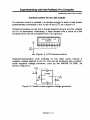
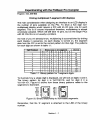
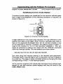
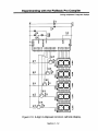
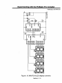
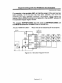
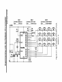
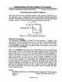
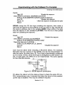
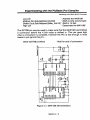
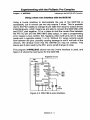
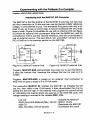
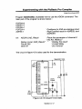
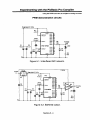
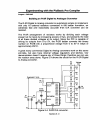
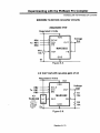
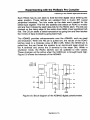
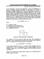
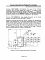
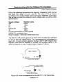
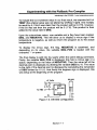
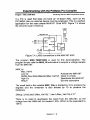
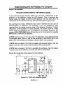
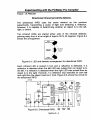
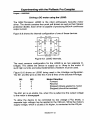
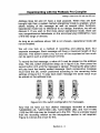
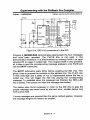
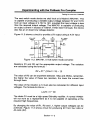
Experimenting with the PicBasic Pro Compiler
Using the PWM command as a digital to analog converter
This is important to know but not terribly useful within our code, we need
to know the value to place into duty that represents the voltage required
on the output . The formula we will use is : duty= Vout /quanta level
Our quanta level worked out as .0195, however this number is too small
for the compiler's integer calculations to handle, therefore we will scale it
up to a more manageable 195 . We will also scale up Vout for a more
accurate result . So our formula now looks like this ; duty = (Vout * 100) / 195
In order to convert the chopped PWM into a smooth analog voltage we
need to filter out the pulses and store the average voltage . R2 and C3 in
figure 5 .1 form an R/C network . The capacitor holds the voltage set by
PWM even after the instruction has finished . The length of time it will
hold the voltage depends on how much current is drawn by any external
circuitry connected to it . In order to hold the voltage reasonably steady,
we must periodically repeat the PWM command to give the capacitor a
re-charge. Just as it takes time to discharge the capacitor, it also takes
time to charge it in the first place . The PWM command lets you specify
the charging time in terms of cycles . To determine how long to charge
the capacitor, use this formula : Charge time = 4 * R (in kQ) * C (in uF) .
For instance, figure 5 .1 uses a 10kO resistor and a 1 pF capacitor : Charge time = 4 * 10 * 1 = 40,
which is 40ms.
Which means it will take 40 cycles to charge the capacitor, however,
since the compiler's PWM command cycle time is dependant on the
crystal frequency, (a 4mHz crystal will give a single cycle time of 5ms, a
20mHz crystal will give a single cycle time of ims etc). To give a cycle
time of 40ms using a 4mHz crystal we use this formula : -.
Cycle = charge time / (20 / OSC)
This will give us a cycle time of 8 to place within the PWM command .
Section-5 - 2