1
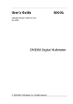
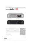
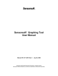
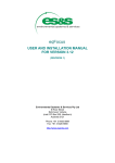
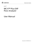
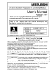
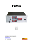
pumppro 6150 advanced liquid level sensor with integrated compressor module User Manual VERSION 1.23 Environmental Systems & Services 8 River Street, Richmond VIC Australia 3121 Tel: +61 3 8420 8999 Fax: +61 3 8420 8900 [email protected] www.esands.com pumppro 6150 User Manual version 1.23 Quality Assurance Statement ISO accreditation ES&S is a company practicing manufacturing techniques specified in AS/NZS ISO9002:1994 standards. The standard covers a quality management system for the supply and manufacture of remote data acquisition instruments for seismic, water and geological event monitoring and the provision of related services. In July 2008 ES&S begun a process to achieve accreditation under the new ISO9001:2008 standard. It is hereby stated that internationally accepted practices are used to supply high quality instrumentation to your organization within a reasonable time interval. Standard practices are used for all areas of manufacture, beginning with the efficient procurement of incoming orders, right through to shipment. Stringent quality assurance procedures are applied to all aspects of manufacturing, including the calibration of scientific instruments against NATA traceable references. Every sensor is accompanied by a test and calibration certificate that can be used as reference information as well as evidence of sensor accuracy. Terms of Warranty The warranty period for a new 6150 pumppro shipped from ES&S is 36 months from the shipment date. This warranty ensures the instrumentation will operate and continue to operate for a period of three years from the purchase date, according to specifications and correct installation. The warranty covers part or complete replacement, repair or substitution of new instrumentation that has failed in part or completely within the warranty period. While every effort has been made to supply robust and user friendly instrumentation, the warranty does not cover instruments incorrectly installed, misused or operated in conditions outside those specified. The warranty does not cover shipment costs for instrumentation, installation or removal and, under no circumstances whatsoever, indirect or consequential losses caused by the failed instrumentation. ES&S believes the warranty conditions to be fair and just and in accordance with standard business practices worldwide. ES&S reserves the right to arbitrate any warranty issues and will ensure that these are treated with the highest standards of professional conduct. At ES&S we believe your investment in our products and services is a good decision and we will therefore ensure all your requirements are met at all times, both now and in the future. Contents Background Information Level measurement using compressed air purge system ................................ 4 6150 pumppro design features........................................................................ 5 Sensor description ................................................................................................... 6 Installation Sensor installation........................................................................................... 7 Tube connection ............................................................................................. 8 Sensor electrical connection ........................................................................... 9 Digital (SDI-12) Mode Electrical Connection ................................. 11 Digital (RS232) Mode Electrical Connection .................................. 11 Analogue Mode Electrical Connection – Voltage ........................... 12 Analogue Mode Electrical Connection – Current ........................... 12 Operation Manual Mode ................................................................................................ 13 Analogue Output Mode ................................................................................. 14 Digital Output Mode – SDI-12 Output ............................................................ 15 Digital Output mode – RS232 Output ............................................................ 17 Menu Functions ............................................................................................ 17 Menu Structure – 6150.................................................................. 19 Display Menu ................................................................................ 21 Datum Menu ................................................................................. 23 Setting Menu ................................................................................. 25 Analogue .................................................................... 25 Alarm .......................................................................... 26 Communication ........................................................... 27 Averaging ................................................................... 29 Density........................................................................ 31 Conversion ................................................................. 31 Screen ........................................................................ 33 Password .................................................................... 33 Diagnostics ................................................................. 35 Pump Settings ............................................................ 36 6150 Operation Diagram………………………………………………………………….. Specifications .................................................................................. inside back cover Ordering information & Contact Details .................................................. back cover pumppro 6150 User Manual version 1.23 July 2008 page 3 Background information Level measurement using a compressed air purge system Level measurement can be achieved using hydrostatic backpressure measuring systems, commonly used in hydrological monitoring applications. A capillary tube is installed where one end is mounted under the water or liquid surface to be measured, while the other is connected to a gas feed above the water surface. The latter is the “dry” tube end. When operating, a very low flow of gas is pumped into the tube from the “dry” end and escapes from the “wet” end in the form of bubbles. Under very low flow conditions, the pressure at the top of the tube is equal to the bottom of the tube where the gas escapes. To overcome the hydrostatic pressure above the submersed tube end, the pressure inside the tube must be increased higher than the hydrostatic pressure. In fact, the tube pressure is exactly the same as the hydrostatic pressure when the flow is very low. Water/ liquid level above the submersed tube end can be calculated using a simple pressure to head of water conversion. Conventional gas purge systems comprise a gas purge regulator (low flow regulator and capillary), gas supply (typically compressed nitrogen) and pressure sensor. However, a relatively new technique is now available whereby a small air compressor is used to generate the hydrostatic pressure condition. This has the advantage of not requiring compressed gas bottles (heavy and bulky), or large site shelters (to house the gas bottle and equipment) which lowers the cost of capital equipment and renders installation, operation and maintenance much safer and easier. The 6150 pumppro is a stand alone hydrostatic level measurement system that requires only a 12Vdc power supply and bubble tube (capillary) connection and has a unique measurement technique that requires a very short compressor run only. When a measurement is activated by an external controller (logger, PLC, RTU etc.), a measurement sequence begins. The compressor runs for several seconds only and charges the capillary tube with a high flow purge. A dwell interval then allows the tube pressure to equalize with hydrostatic pressure for a set time period. After this, a pressure measurement is taken, processed and displayed or output to the controller. There are several advantages using this type of measurement technique as summarized below: • • • Very short compressor run time ensuring long compressor life No compressed gas storage vessel required, making the 6150 smaller and safer. High flow air purge through capillary will ensure capillary remains free from silt – a common problem with low flow gas bubblers used in high silt load applications. pumppro 6150 User Manual version 1.23 July 2008 page 4 6150 pumppro design features Several design features are incorporated into the pumppro design to ensure ease of installation, operation and maintenance as well as functionality for various applications: • • • • • • • • • • • Stand alone operation – requires bubble tube and battery power only Easy to install – wall mounted using standard hardware Modular – 6100 levelpro used with 6150 pumppro module. 6100 can be user upgraded to 6150 using separate pumppro module Backlit multi-line LCD display to obtain readings and for configuration Simultaneous analogue and digital output – user selectable 4-20mA or 0-1V/ 2.5V, RS232 or SDI-12 data. All outputs are standard features. Units of measurement selection – metric and imperial for liquid head, volume and flow (flow calculations not implemented in version 1.22). Firmware upgradeable using terminal application (eg. Hyperterminal ® ) High quality power and signal cable sockets fitted, supplied with cables Zero maintenance condensation water discharge mechanism fitted Excellent temperature stability Differential pressure measurement providing higher accuracy. 6150 pumppro Battery Figure 1. 6150 pumppro level measurement system Bubble tube pumppro 6150 User Manual version 1.23 July 2008 page 5 Sensor Description The pumppro 6150 is a level measurement system based on the levelpro 6100 advanced liquid level sensor. It provides measurement of the attached capillary tube pressure, processing/ conversion, output to recorders and controllers and control over the 6150 integrated compressor module. The 6100 is able to provide pressure measurement only and with the 6150 module forms a stand alone measurement system requiring only battery power and capillary tube connection. Measurements are converted to metric or imperial units including linear distance (metres and feet ) of head, tank volume and stream flow#. The 6100 features a 4 line LCD display (dot matrix type) that will show measurements, messages and instructions for in-built functions. Users have access to a keypad on the 6100 front display panel for sensor configuration and operation. Two multi-pole connector sockets are fitted on the bottom end of the 6150 sensor for power and signal cable connection as well as a ¼” tube fitting for connection of the capillary (bubble) tube. An adapter is included with the sensor for connection of 3/8” bubble tube. The 6150 module houses all electromechanical items required to provide the air purge for level measurement, including precision piston air compressor, solenoid valves and other pneumatic components. During manufacture, the 6100 levelpro is fitted to the 6150 pumppro module cover using internal retaining hardware. levelpro 6100 advanced liquid level sensor pumppro integrated compressor module ¼” tube fitting with adapter Water resistant high quality signal and power connectors Figure 2. 6150 pumppro front view pumppro 6150 User Manual version 1.23 July 2008 page 6 Installation Sensor installation The pumppro 6150 must be wall mounted using the 4 wall mounting slots provided at the top and bottom mounting flanges. ! Install in vertical position ONLY to ensure correct condensation water accumulator operation. Mounting screws are not supplied as wall materials vary. You must obtain the correct screws suitable for your wall material. It is recommended you also obtain flat washers to protect the 6150 epoxy coating finish around the wall mounting slots. Slots are 6mm wide x 12mm long. Equipment required • • • • • • • pumppro 6150 supplied with new Signal and power cables sensor Tube adapter (for 3/8” tube) Condensation water drain tube 4 screws and washers for mounting 6150 to wall – to suit wall material Screwdriver or suitable tool for screws 2 x adjustable spanners, 150mm minimum for tube connection Some points to consider • The sensor must be installed out of rain, snow and direct sunlight. Air borne moisture and dust will not affect the sensor operation. • Install the 6150 sensor so the display is at comfortable eye level to avoid staff having to strain by bending over or standing on inappropriate objects. • The condensation water drain tube must be fitted to route the condensation water to the outside. If installing the tube inside an office or building, you must ensure there is sufficient tubing to reach the outside or a water accumulator vessel placed underneath the sensor. The 6150 compressor will generate more condensation water in humid tropical areas compared to mild dry climates. From laboratory tests, it can be assumed the worst case for the amount of water is 10ml per week (2 second compressor cycle every 15 minutes). A 500ml vessel will fill up within 2 years (theoretically). However, office and building environments are typically dryer and the amount of water accumulated will most likely evaporate at a similar rate. Drier air also results in much less condensation water. • Using the sensor or drilling template, mark the holes on the wall while ensuring there is adequate clearance around the sensor to access the fasteners used to secure the sensor. It is recommended to use plastic wall plugs for concrete walls with self tapping screws, self cutting metal screws for sheet metal walls and wood screws for wooden walls. Remove the sensor or template and drill the holes as required. • Fasten the sensor vertical to the wall using the correct screws. The display must be at the top and connectors at the bottom. pumppro 6150 User Manual version 1.23 July 2008 page 7 Tube connection A ¼” brass tube fitting with nut, spacer and ferrule is provided at the bottom of the 6150 sensor. ¼” outside diameter (O.D.) bubble tubes may be connected directly. However, if using 3/8” O.D. bubble tube you must use the provided brass adapter. To connect any tube or adapter you MUST use two spanners to prevent the ¼” sensor tube fitting from rotating. The tube nut size is 9/16” and bulkhead fitting nut size, located at the bottom of the 6150, is 5/8”. ! • Ensure the ¼” tube end is square and clean of burrs, dirt and grime. ¼” bubble tube ¼” fitting on 6150 • • ! Ferrule and spacer Nut Figure 3. Crimp tube fitting components Push the end of the tube into the fitting. You may need to loosen the nut and ferrule assembly slightly. If in doubt, remove the nut and ferrule and slide onto the tube end first before connecting the nut to the fitting again. Once hand tight, use two adjustable spanners to tighten the nut ¾ of a turn only. This will crimp the main ferrule onto the outside of the tube and form a seal. Remove the nut and tube assembly and check the condition of the ferrule before replacing it. This time you need only tighten the nut ¼ of a turn since the ferrule is already crimped. DO NOT tighten the nut further than ¾ of a turn from the hand tight position. Doing so may cause leaking due to flaring of the crimp ferrule and the nut thread will become damaged. To connect a 3/8” O.D. bubble tube: • Remove the ¼” nut and ferrule assemble from the 6150 brass tube fitting • Connect the supplied 3/8” to ¼” tube adapter to the 6150 brass fitting. Finger tight only. • Using suitable spanners, tighten the ¼” (small) adapter nut ¼ turn only. ! DO NOT tighten the nut further than ½ turn from the hand tight position. Doing so may cause leaking due to flaring of the crimp ferrule. The crimp ferrule type fittings used for bubble tube connection do not require the use of a sealing compound. Doing so has no effect on the quality of seal formed. To prevent leaks due to tube shrinkage at the fittings you may use suitable tube spigots. These prevent the tube from being crushed by the crimp ferrule and the tube loosening from the ferrule due to ageing. pumppro 6150 User Manual version 1.23 July 2008 page 8 Sensor electrical connection The pumppro 6150 sensor is supplied with 2 cables with connectors fitted to match the sensor sockets on the bottom of the sensor. The multi-pin connector is used for connection of all signal lines while the 2 pin connector and cable is used only for providing 12Vdc power including compressor power. The following tables provide details of all signal and power connections. Cable Conductor Designation – multi-pole connector 1 2 3 4 5 6 7 8 9 10 11 12 13 14 15 16 17 18 RED BLACK BLUE BROWN WHITE DARK GREEN YELLOW VIOLET GREY PINK ORANGE RED-WHITE BLACK-WHITE ORANGE-WHITE BROWN -WHITE GREEN-WHITE LIGHT GREEN BLUE -WHITE Not used Ground Ground RS232 Rx (receive data) RS232 Tx (transmit data) RS232 handshaking SDI-12 data High Level alarm output Low Level alarm output Switched power enable Not used Not used Not used Not used Not used Firmware loading enable Analogue output (voltage) Analogue output (current) Plug with cable Front View 1 3 7 12 16 Sensor signal connector – Multi-pole socket for RS232, SDI-12, analogue output, other I/O and logger switched power Ground Ground of common is connected directly to sensor analogue and digital ground. Both BLACK and BLUE signal wires are ground and either or both may be used. RS232 Rx This connection is an input that allows the sensor to accept RS232 commands from a controlling device (DTE). Ensure commands are sent to the sensor with true RS232 voltage levels such as those via a dedicated RS232 signal level converter. RS232 Tx The 6150 sensor outputs RS232 data at 5.0V EIA/TIA-232 levels. All RS232 parameters are fixed except the baud rate. Select the desired baud rate through the Settings menu. Only one digital output can be selected at any one time. SDI-12 data The SDI-12 data line is used exclusively for SDI-12 bi-directional communication. This line remains at high impedance until the sensor responds to a correctly addressed command at which time a 0-5V logic data signal is transmitted to the SDI-12 controller in accordance with SDI-12 protocol version 1.3. pumppro 6150 User Manual version 1.23 July 2008 page 9 High Level Alarm Output This connection is will be driven from 0V to 5V when the preset threshold for the “high” level alarm is exceeded. See page 26 for alarm setup instructions. Low Level Alarm Output This connection is will be driven from 0V to 5V when the preset threshold for the “low” level alarm is exceeded. See page 26 for alarm setup instructions. Analogue Enable Connecting +12Vdc to the PINK wire forces the 6150 sensor to switch on and take a reading. The analogue output is also activated for the duration of applied +12Vdc. This feature is required for data loggers and recorders that provide a +12Vdc switched power output being a means to activate a sensor measurement sequence. Loggers and controllers must be programmed to activate the 6150 sensor, wait for the measurement time (eg. 30 seconds), take a reading of the analogue output and deactivate the sensor by removing +12Vdc from the PINK wire. If +12Vdc is held to the PINK wire, the sensor will remain switched on but a measurement sequence never occurs again after the first unless the sensor is in Continuous Mode. Analogue Output - Voltage This connection will output voltage (0-1V or 0-2.5V) in proportion to measurements with reference to ground. A high impedance voltage input equipped recorder can be used to measure the output on this connection. Select voltage output by configuring the sensor through the Settings menu. Only one analogue output can be selected. Analogue Output - Current Use this connection if 4-20mA output signal is desired. Output is a ground referenced current source that can be connected to current measuring devices. For 12 volt operation, the load resistance must not exceed 450ohms. Select current output by configuring the sensor through the Settings menu. Cable Conductor Designation – 2 pin power connector 1 2 RED BLACK Battery power + Battery power - 2 1 Power Connector – 2 pin Battery +12Vdc - RED The red wire is used for +12Vdc battery supply connection. The 6150 sensor must have the battery cable attached to provide the higher power requirements for the compressor. Battery power is also provided to the electronics module (levelpro 6100 sensor), therefore the RED wire from the signal cable is not used. Ground 0Vdc – BLACK Connect this wire directly to battery (-) terminal. This wire MUST be connected to the battery to ensure the required current load capacity is available for the compressor. WARNING: ! DO NOT reverse the battery cable connections while either the BLUE or BLACK signal cables are connected to ground or damage will result. pumppro 6150 User Manual version 1.23 July 2008 page 10 6150 Sensor Output Configuration The following shows sensor electrical interface to specific recorder/ controllers (using appropriate sensor configuration settings). Digital (SDI-12) Mode Electrical Connection To operate the 6150 sensor in SDI-12 mode, 2 connections are required. The DC power cable must be used to supply power to the sensor at all times. While power is supplied, the sensor is in a sleep state that causes very little power draw. Incoming commands will be processed only if the sensor address programmed during configuration matches the command address character. In SDI-12 mode the sensor will only respond to fully compliant SDI-12 commands that include the “break” character. The table below shows the pin-out for an ES&S SDI-12 connector used for connecting sensors to SDI-12 enabled recorder/ controllers. 6150 colour designation 5 pin male plug E 7 2,3 YELLOW BLACK or BLUE SDI-12 data Ground B C A D B C Digital (RS232) Mode Electrical Connection To operate the 6150 sensor in RS232 mode 3 connections are required. The DC power cable must be used as the RS232 DTE does not provide continuous power to the sensor. While power is supplied, the sensor is in a sleep state that causes very little power draw. An incoming, correctly addressed RS232 command will cause the sensor to wake and process the command. No handshaking is required as the 6150 sensor wakes upon an incoming, correctly addressed RS232 command. During command processing the sensor display remains off. The table below shows connection to a 9 pin female “D” connector that connects directly to a standard computer serial port. 6150 5 4 23 colour designation WHITE BROWN BLACK or BLUE 1 2,3 pumppro 6150 User Manual RS232 Tx RS232 Rx Ground 2 pin power cable RED BLACK RS232 RxD TxD Ground 9 pin “D” female 2 3 5 1 2 3 4 5 9 8 7 6 Supply +ve Ground version 1.23 July 2008 page 11 Analogue Power Mode Electrical Connection The 6150 sensor can be configured to output either analogue current or voltage when interfacing to traditional loggers and recorders. The configuration to select the type of analogue output is part of the menu functions. Voltage The measurement sequence of the 6150 sensor is activated using Analogue Enable (+12Vdc on PINK wire). Ensure your logger/ controller is able to provide switch control of this connection. Applying continuous power to the PINK wire will invoke one measurement sequence only. The display will show “Analogue output” in this mode. Use the Analogue Output menu to select the type of output and span (0-1V or 0-2.5V) The following shows analogue voltage output connection and includes pin-out for an ES&S connector used for connecting sensors to analogue input equipped devices. 6150 10 2,3 17 colour designation PINK BLACK or BLUE LIGHT GREEN Analogue Enable Ground Voltage signal output 3 pin male plug A C B C A B 4-20mA Current Loop The measurement sequence of the 6150 sensor is activated using Analogue Enable (+12Vdc on PINK wire). Ensure your logger/ controller is able to provide switch control of this connection. Applying continuous power to the PINK wire will invoke one measurement sequence only. The display will show “Analogue output” in this mode. Use the Analogue Output menu to select 4-20mA current. The following shows analogue current output connection and includes pin-out for an ES&S connector used for connecting sensors to analogue input equipped devices. 6150 10 2,3 18 colour designation PINK BLACK or BLUE BLUE-WHITE Analogue Enable Ground Current signal output 3 pin male plug A C B C A B pumppro 6150 User Manual version 1.23 July 2008 page 12 Operation Manual Mode In manual power mode the sensor will take a level measurement and display it on the LCD display. Connect the 2 pin DC power cable to a 12V battery and sensor DC power socket. Once power is connected to the sensor display shows (serial no. example only) To obtain a measurement from the sensor: Press 6150 Integrated pump system Serial# 00210 Firmware V1.21 >Menu Reading Display shows ON Please wait .. Press and ok to activate a measurement sequence Level After 30 seconds display shows (example only) +43.756 m To switch off, do not press any keys for 25 seconds. The sensor will automatically switch off thereafter or revert to another power mode. You may also press esc twice to switch the sensor off. Display shows Or the sensor will revert to another power mode If +12Vdc is applied to Analogue Enable Or Self Run Mode is on, display shows: pumppro 6150 User Manual version 1.23 July 2008 Analogue Mode page 13 Analogue Output Mode In analogue output mode the sensor will take a level measurement and output a corresponding analogue voltage or current signal (depending on configuration). Connect the sensor as described in section Installation- Analogue Output Mode. While switched +12Vdc is applied to the Analogue Enable (PINK) terminal, analogue output will be active continuously and updated as level changes occur. Only one compressor/ measurement cycle is activated per low to high switch transition. While switched +12Vdc is applied, the display will show: Analogue Mode To display the current measurement: Level Press Display shows ON +43.756 m (example only) To switch off displayed value and revert back to Analogue Output Mode: Press esc Analogue Mode twice. Display shows Or simply wait for around 25 seconds. The unit will automatically switch back to Analogue Power Mode, as this is the prevailing mode. Analogue Output Mode always takes preference over Manual Mode. If the display is activated to show a reading while in Analogue Output Mode, the analogue output will not be interrupted. Analogue output is available and stable after 30 seconds from the time +12Vdc is applied to Analogue Enable. Switched power is typically removed after a reading has been attained. Any incoming SDI-12 or RS232 commands with an address matching the sensor address will be processed as highest priority. This ensures digital sensor data is unaffected while users are configuring the sensor or viewing measurements on the display. pumppro 6150 User Manual version 1.23 July 2008 page 14 Digital Output Mode The pumppro 6150 provides digital output as either SDI-12 or RS232 (user configurable). SDI-12 Output The 6150 sensor provides a fully compliant SDI-12 output whereby digital data is transferred through a single conductor cable (plus common). Controller devices must themselves be fully compliant to SDI-12 protocol version 1.3. For interface, please refer to section Installation - Digital (RS232) Mode Electrical Connection for correct electrical connection. In SDI-12 mode the sensor is permanently powered by 12Vdc supply through the dc battery power cable. The sensor immediately enters an idle state where very little power is consumed. Incoming SDI-12 commands will only be processed if the preceding address matches the current sensor address. Commands received with matching address will invoke a sensor response according to the type of command. The display remains off during command processing. If the sensor was started in manual or analogue mode, a correctly addressed SDI-12 command will be processed as priority and override all other modes. The current SDI-12 Command Set is shown on the next page. It describes the commands and responses applicable to the 6150 sensor. A menu is available in the 6150 that can be used to change basic SDI-12 parameters and includes setting to enable/ disable SDI-12 output, change sensor address and format the output data. See section Settings – Communications – SDI-12. pumppro 6150 User Manual version 1.23 July 2008 page 15 SDI-12 Command Set Command Response Description ?! Eg: ?! a 1 <CR><LF> reveals sensor address sensor address is “1” aI! Eg. a13cccccccmmmmmmvvvsssss 118ESandS 6150 11220202 sensor identification 1I! aM! Eg. 1M! atttn 10301<cr><lf> 1 buffers address time, 1 request reading aD0! Eg. 1D0! apd.ddd 1+1.234 1+0001.234 returns buffer contents or measurement. leading zeros ON aR! Eg. apd.ddd 1+1.234 1+0001.234 1R! not implemented in version 1.21 new measurement 1, 030s measurement data field, service (1) sent when is available returns new measurement without D0! Command leading zeros ON aAb! Eg. 1A2! ar 21 change sensor address from 1 to 2 a b ttt n p r dd.ddd cccccccc mmmmmm vvv sssss = = = = = = = = = = = 1 character 1 character 3 characters 1 character 1 character 1 character variable 8 characters 6 characters 3 characters 5 characters • # % sensor address new sensor address measurement time (secs) number of data fields polarity ( + or -) return code (1 = all ok) measured data Vendor ID sensor model sensor firmware version sensor serial number % # * Leading zeros can be switched off and on through the Settings – Communications – SDI-12 menu (see examples above). When switched on, the response from the 6150 sensor is always of fixed length, no matter the value. When leading zeros are off, the string length can vary according to the actual sensor output 1+0001.234 leading zeros ON 1+1.234 leading zeros OFF Polarity sign, whether + or – will always be included in response. The 6150 sensor has a variable measurement time depending on the measurement sequence parameters programmed in Settings – Pump Settings and if averaging is used (averaging implemented in version 1.21). pumppro 6150 User Manual version 1.23 July 2008 page 16 RS232 Output The 6150 sensor has an RS232 interface fitted as standard and is accessible using the designated wires in the signal cable. A 9 pin “D” connector, suitable for direct connection to most RS232 equipped communication equipment, can be factory fitted to allow easy connection. The 6150 sensor is a Data Communication Equipment (DCE) device and can be directly connected to Data Terminal Equipment (DTE) which includes modems, computers and telemetry systems. Please refer to the section Installation – Digital (RS232) Mode Electrical Connection for installation instructions. Commands and responses to and from the sensor through RS232 are the same as for SDI-12 communication. A command summary can be found on the previous page. However, you may omit the “!” from the command string as this character is used to exclusively terminate an SDI-12 command. Communication parameters: To communicate to the 6150 sensor via RS232, the DTE must be configured with the parameters shown below. No handshaking is required as the 6150 wakes upon incoming commands. The sensor baud rate is adjustable through the Settings – Communications – RS232 menu. Baud rate Parity Data bits Stop bits = 1200 to 115000 bps = none =8 =1 To send commands, you must send the ^M (carriage return) character at end of command strings. For example: Computer sends: 1M!<CR><LF> activate measurement 6150 responds: 10301<CR><LF> address 1, 030 seconds measurement, 1 data field Service request – returned once reading is loaded into buffer (after 30 seconds) 1 Computer sends: 1D0!<CR><LF> Read buffer 6150 responds or 1+0001.234 1+1.234 Data, leading zeros on, 3 decimal places Data, leading zeros off, 3 decimal places Set the sensor address using the Settings – Communications – SDI-12 menu. Trailing zeros always switched on. Ensure your applications waits for the sensor measurement time to elapse or receipt of service request (1). pumppro 6150 User Manual version 1.23 July 2008 page 17 Menu Functions When the sensor ON button is pressed you may enter the Settings menu or activate a measurement. Press Display shows ON ok Press Display shows >Menu Reading >Display Datum Settings Password To navigate through the menus, use the following: Use and keys to scroll through menu items. Use ok to enter into a sub-menu item or confirm and save a change. Use esc to revert back to the previous menu level or cancel an operation. Pressing esc while in the highest menu level will cause the sensor to switch off completely or revert to the previous power mode. pumppro 6150 User Manual version 1.23 July 2008 page 18 Menu Structure - 6150 Main Menu Structure Display Menu Level Volume Discharge Display Units Datum Menu Settings Menu Level mm m in ft kPa psi Volume litres m3 gal kl yes no Enabled? Type Abs Rel Value value Analogue Output Type Current Voltage F/S(m) Span 4-20mA 0-1V 0-2.5V Value F/S(m3) Value F/S(m/s) Value Alarm Enabled? High/Low config. Communicatio RS232 Baud rate 1200 2400 4800 9600 19200 38400 57600 115000 SDI-12 Enabled? yes no Address Value Data format Password Enter Password pumppro 6150 User Manual version 1.23 July 2008 page 19 L/Z – y/n D/P - value Menu Structure – 6150 – cont’d Averaging Enabled yes no Mode Standard Running Settings Density value Conversion Level Volume Screen Password Sample interval value No. of samples value Type Standard User def. Standard Melb Sydney Aus Europe Equator British User defined value Type Cylinder Tank Cylinder dia. value Tank length value Backlight on off Cursor underline flashing block Enable yes no Change value Diagnostics Diagnostic Menu Pump Settings Differential on off Purge value Drain value Dwell value Self Run value AutoZero pumppro 6150 User Manual version 1.23 July 2008 page 20 Display Menu Access the display menu by pressing any button except ON while the sensor is showing measurements. >Display Datum Settings Password Display will show Press ok to enter submenu Display menu: >Display Level Units meter or Press to move cursor Display menu: Display Level >Unit meter Display: shows the currently displayed parameters when readings are taken. Units: shows the currently displayed unit when readings are taken. Display menu - Display Press ok Select Display: Level to enter Use Up/Dn to change Press Select Display: Volume or Use Up/Dn to change Level: Selecting this parameter outputs a linear distance of liquid level Volume: Selecting this parameter outputs a volume of liquid in accordance with a particular vessel shape. Press ok on the selected parameter to save the setting pumppro 6150 User Manual Select Display: Volume Change saved! Use Up/Dn to change version 1.23 July 2008 page 21 Display menu - Units Press ok Press to set parameter Select unit for: >Level Volume or Select unit for: Level >Volume Each parameter has different units. Use this menu to select which parameter you want to change the units of measurement for. Display menu – Units – Level Press ok Level unit: m to set units Use Up/Dn to change Press Level Units: psi or Use Up/Dn to change mm m psi kPa in ft all measurements are in millimeters using kPa to meters conversion all measurements are in meters using kPa to meters conversion raw pressure output in pounds per square inch raw pressure output in kilo Pascals all measurements are in inches using kPa to feet conversion all measurements are in feet using kPa to feet conversion Display menu – Units – Volume Press ok to set units Volume unit: m3 Use Up/Dn to change Press Volume unit: gal or Use Up/Dn to change lit m3 gal kl all measurements are converted to liters using selected tank shape all measurements are converted to cubic meters using selected tank shape all measurements are converted to imperial gallons using selected tank shape all measurements are converted to kiloliters using selected tank shape To save press ok pumppro 6150 User Manual Volume unit: psi Change saved! Use Up/Dn to change version 1.23 July 2008 page 22 Datum Menu Sensor measurements can be referenced to a known level called datum offset. Two types of datum offset calculations are available as shown below. Access the datum menu by pressing any button except ON while the sensor is showing measurements. Display >Datum Settings Display will show Press ok to enter submenu Datum menu: >Enabled Type Value No ABS +0.000 Datum nenu: Enabled >Type Value No ABS +0.000 or Press to move cursor Enabled: set to YES to add datum value to reading. Type: shows the type of datum used. ABS – Datum offset value is added to all readings. REL – Reading is taken. Datum is subtracted from reading and result is added to reading. This has the effect of forcing the current reading to be the same as the datum offset. Use this when entering exact staff gauge reading for water level measurement Value: This is the datum offset value to be used in the calculation. Datum menu - Enabled Press ok to enter Datum enabled ? No Use Up/Dn to change Press or Datum enabled ? Yes Use Up/Dn to change Press ok to save parameter to save the setting pumppro 6150 User Manual Datum enabled ? Yes Change saved! Use Up/Dn to change version 1.23 July 2008 page 23 Datum menu - Type Press ok Datum type: Absolute to enter Use Up/Dn to change Press Datum type: Relative or Use Up/Dn to change Press ok Datum type: Relative Change saved! Use Up/Dn to change to save parameter to save the setting Datum menu - Value Press ok Datum value(m) +0000.000 to enter Dn-move, Up-change Press Datum value(m) -0000.000 to change sign Dn-move, Up-change or Press Datum value(m) +0000.000 to move one Dn-move, Up-change character to the right Press to increase digit Datum value(m) +1000.000 Dn-move, Up-change Example only. Continue this process to adjust all digits. Once finished, press ok to save the new value. Datum value(m) +1000.000 Change saved! Dn-move, Up-change Note: Datum values only apply to digital output (SDI-12 or RS232). Analogue output (voltage or current) is not affected by the datum value. Datum for analogue output is typically applied within the recorder/ controller to which the sensor is connected. pumppro 6150 User Manual version 1.23 July 2008 page 24 Settings Menu The Setting menu is used to configure the sensor for the desired operation and includes functions to set up analogue and digital output as well as housekeeping functions. Each Setting menu item is described in detail in the following sections. To access the Settings menu it must be unlocked first by entering a password (see Main Password, page 31). By default, the Settings menu is unlocked. Press ok to enter submenu Settings nenu: >Analogue Alarm Communication Settings – Analogue Use the analogue menu to set the type and range of analogue output. Two types are available, current and voltage. The full scale analogue output can be adjusted, effectively re-ranging the sensor. Full scale adjustment must be set for level, volume and discharge separately. Press ok to enter submenu Analogue nenu: >Output F/S(m): +10.000 F/S(m3): +0.0E+00 Settings – Analogue – Output Use this menu to select either current (4-20mA only ) or voltage output. Select the span for the type of analogue output by entering the respective submenus. Press Press ok to enter submenu ok to enter submenu Analogue output: >Type: Current Span (mA): 4-20mA Span (V): 0-2.5V Output type: Current Use Up/Dn to change Use to change to Voltage output and press pumppro 6150 User Manual version 1.23 July 2008 ok to save page 25 Settings – Analogue – F/S(m) Use this parameter to assign the full scale level, pressure, volume or flow for analogue output. The value selected here will be that represented by 20mA (current) or 1V/ 2.5V (voltage). Enter the value desired in the next submenu. Press ok to enter submenu F/Scale (m): +0010.000 Dn-move, Up-change Use to change to sign/ value and right. Press ok to move one digit to the to save. Change the volume full scale ( F/S(m3) ) and discharge full scale ( F/S(m3/s) ) in the same way. Please note that discharge is not implemented in version 1.22. Settings – Alarm A digital output provides alarm control for external devices. Output is at 0V when off and at 5V when active. This is a low current driver capable of driving high impedance external circuitry only. Press ok to enter submenu Enable or disable the alarm as required Alarm menu: >Alarm use: Disabled High config Low config Alarm usage: Disable Use Up/Dn to change Set the high alarm trigger level and reset level in the next menu Set the low alarm trigger level and reset level in the next menu High settings: Trigger +0.000 Reset +0.000 Low settings: Trigger +0.000 Reset +0.000 Use both high and low alarms to set an alarm window. You must however ensure the high trigger and reset values are always higher than the low alarm values or the alarm may never trigger and/or reset. pumppro 6150 User Manual version 1.23 July 2008 page 26 Settings – Communication The Communication menu is used to configure digital output. Both RS232 and SDI-12 settings can be adjusted as shown in the following menus. Press Communication nenu: >RS232 SDI-12 to enter submenu ok Settings – Communication – RS232 Only the baud rate can be adjusted for RS232 communications. All other parameters remain fixed as shown below: No. of data bits: No of stop bits: Parity: 8 1 none To set RS232 baud rate: Press ok to enter submenu RS232 settings >Baud rate: 9600 Press ok to enter submenu RS232 baudrate: 9600 Use Up/Dn to change Set the baud rate compatible with the DTE device to which the sensor is connected. The possible baud rates are shown below: 1200 2400 4800 9600 19200 38400 57600 115000 Use or to change RS232 baudrate: 19200 Use Up/Dn to change baud rate, press ok pumppro 6150 User Manual to save RS232 baudrate: 9600 Change saved! Use Up/Dn to change version 1.23 July 2008 page 27 Settings – Communications – SDI-12 The SDI-12 settings menu can be used to enable SDI-12, set sensor address and configure the output data format. Press to enter submenu ok SDI-12 settings: >Enabled No Address 0 Data format SDI-12 enable: Press No to enter submenu ok Use Up/Dn to change Change the status to “Yes” to activate SDI-12 communications. You cannot use RS232 output in this mode, however, this does not affect analogue output which can be used simultaneously, as previously configured. Address Press to enter submenu ok SDI-12 address: 0 Use Up/Dn to change Use or to change SDI-12 address: 1 Use Up/Dn to change Data Format Use this menu to change the SDI-12 output data format. This feature is particularly useful when recorders require a particular format to ensure data is received correctly at all times. Leading zeros ensures the data string is always of a fixed length while the number of decimal points can be changed to allow output of very large or very small numbers. Press ok to enter submenu SDI-12 format: >Leading zeros:Yes Decimal Pts: 4 Use the respective menus to set leading zeros off or on and set the number of decimal points between 0 and 4. Note: The 6100 is able to output numbers up to 8 digits. When outputting large numbers (level in mm or inches, volume in litres etc), set the number of decimal places to 0 or 1. Similarly, set the number of decimal places to 2,3 or 4 when outputting small numbers. pumppro 6150 User Manual version 1.23 July 2008 page 28 Settings – Averaging The Averaging menu allows users to configure the sensor to take several readings that are averaged. The averaging process outputs the average reading of a preprogrammed number of readings. Press ok to enter submenu Averaging menu: >Enabled No Mode STD Settings Averaging – Enabled Select YES to enable averaging output. Press ok to enter submenu Averaging Enabled: No Use Up/Dn to change Averaging – Mode Select standard averaging (STD) for typical averaging whereby a number of readings are added then divided by number of readings at the end of the process. Select Running (RUN) for producing running average that takes the last number of readings to produce an averaged reading every consecutive reading. This function is only available for 6100 sensors, not 6150 sensors. Press ok to enter submenu Averaging Mode: Standard Use Up/Dn to change Press Averaging Mode: Running to change Use Up/Dn to change Averaging – Settings This menu allows users to change the averaging parameters as required. There are two parameters, sample interval and number of samples. The total averaging time is the product of sample interval (in seconds) and no. of samples. For running averaging the averaging time is the same as the sample interval (6100 only). Press ok to enter submenu pumppro 6150 User Manual Averaging Settings: >Sample Interval 1 No. of Samples 60 version 1.23 July 2008 page 29 Sample Interval Change the sample interval between 1 and 60 seconds. The sample interval is the time between readings in seconds. When selected, the averaging process forces the sensor to take level readings at this interval. The number of readings taken depends on the programmed number of readings (see No. of Samples). No. of Samples Select the number of samples for averaging between 2 and 60. Number of samples is the number of individual level readings the sensor will take before outputting an averaged reading. Total averaging time is the number of samples x sample interval (minimum 2 seconds, maximum 3600 seconds). Standard Averaging – sensor takes a number of readings, adds all readings together and divides total by number of readings. This produces an averaged reading even if some or all readings vary substantially. Use this setting to measure tidal levels with waves superimposed onto desired sea level reading. Once reading is output, a new averaging interval begins. Averaged reading = Sum { reading1 + reading2 + readingn } No. of readings readings Averaged reading Sample Interval x no. readings Running Averaging – sensor takes a number of readings, adds all readings together and divides total by number of readings as per Standard Averaging. In standard averaging the process begins anew once the averaged reading is output for the first time. For running averaging and output is generated after each sample interval using the latest no. of samples. This way an averaged reading is output much faster after every sample interval (1 to 30 seconds). The sensor remains on continuously in this mode as this is a continuous output. Running average 1 Running average n Running average 2 Running average 3 When averaging is enabled the main display will show that the reading is averaged. Running average is only available for 6100. For example: Level (Ave:STD) +43.756 m pumppro 6150 User Manual or Level (Ave:RUN) +43.756 m version 1.23 July 2008 page 30 Settings – Density When measuring level in liquids of density other than fresh water, a density factor can be programmed into the sensor to ensure pressure to level conversion remains accurate. For this sensor a relative density is assumed whereby freshwater (ultrapure) has a density of 1.0000. Press ok to enter submenu Density menu: +001.0000 Dn-move, Up-change Liquid density is the ratio of weight to volume. Fresh water is lighter than seawater, therefore seawater has a higher density. Some liquids other than water have a density less than 1. Simply enter the density of the liquid in the above menu. The readings taken thereafter will be automatically converted to the correct level. Settings – Conversion The conversions menu is used to set the type of conversion used by the sensor to provide a calculated output. Press ok to enter submenu Conversion menu: >Level Volume Setting – Conversion – Level Use the level conversion menu to select kPa to distance conversion factor. All conversions are based on mm/kPa units. Press ok to enter submenu Level conversion: >Type: STD Standard: Aus STD User defined Type: Standard: Select between a Standard and user defined conversion If a STD conversion type is used, this submenu allows selection the Standard used to convert kPa to millimeters water. Standards: Australian Sydney: Melbourne: 102.15 mm/kPa 102.07 mm/kPa 102.04 mm/kPa British: Europe: Equator: 101.97 mm/kPa 101.85 mm/kPa 102.25 mm/kPa User defined: If a user defined type is used, this submenu allows entry of a non standard conversion in mm/kPa. pumppro 6150 User Manual version 1.23 July 2008 page 31 Settings – Conversion – Volume - Cylinder Vertical cylinder (tank) is oriented as shown. Enter diameter (d) of the tank only. Level sensor will calculate tank volume based on measured height of liquid. For bubble tubes installed with end fitting above tank floor, use Datum menu to adjust volume. For horizontally oriented cylindrical tank, enter diameter (d) and length (L) as shown. Ensure internal dimensions are used only. For bubble tubes installed with end fitting above tank floor, use Datum menu to adjust volume. d d L Settings – Conversion – Volume - Box Box shaped tanks have vertical sides as shown. Enter length (L) and width (W) of the tank only. Level sensor will calculate tank volume based on measured height of liquid. For bubble tubes installed with end fitting above tank floor, use Datum menu to adjust volume. W L Settings – Conversion – Volume - Hopper W This is an inverted pyramid shape commonly used in the process industry. Enter length and width dimensions in reference to height (H) . Level sensor will calculate tank volume based on measured height of liquid. For bubble tubes installed with end fitting above tank floor, use Datum menu to adjust volume. pumppro 6150 User Manual version 1.23 July 2008 L H page 32 Settings - Screen Use this menu to adjust screen settings. Press ok to enter screen settings menu. Screen settings >Backlight ON Cursor Block Contrast Backlight enable: ON Use Up/Dn to change The display backlight can be switch on an off using this menu. Screen settings Backlight ON >Cursor Block Contrast Cursor shape: Block Use Up/Dn to change By default the cursor is a flashing block. Use this menu to change it to underline if desired. Screen settings Backlight ON Cursor Block >Contrast Contrast: 1 Display contrast can be adjusted in this menu between 1 and 7. Settings - Password By default the settings menu can be accessed at all times. However users have the facility to password protect the settings menu to prevent unauthorized access. Once a password has been enabled in the settings menu, this menu is only available after the password is entered to unlock it. To unlock the Settings menu you must enter the correct password consisting of 4 numbers between 0 and 9. This must be done in the main menu. Once password is entered press OK. If correct: or if incorrect: Enter password: 1234 PIN accepted! Dn-move, Up-change Enter password: 4321 PIN rejected! Dn-move, Up-change To lock the Settings menu again, enter the password again until it is accepted. pumppro 6150 User Manual version 1.23 July 2008 page 33 To change the password and enable/ disable you must get access to the Settings menu. Settings menu: Screen >Password Pump settings Password settings: Enabled Yes >Change To change password use the up and down Change password: 1234 Dn-move, Up-change buttons and press ok when finished to accept the new password. The password menu allows you to enable or disable a password used to protect the sensor settings from unauthorized access. When in the Main Menu, the password must be entered to allow access to the Settings menu only. All other menus are freely accessible. If password is disabled: Display Datum Settings >Password Enter password: Password disabled, Press ESC to return If password is enabled: Enter password: **** Display Datum Settings(locked) >Password Dn-move, Up-change To unlock the Settings menu you must enter the correct password consisting of 4 numbers between 0 and 9. Once password is entered press OK. If correct: or if incorrect: Enter password: 1234 PIN accepted! Dn-move, Up-change Enter password: 4321 PIN rejected! Dn-move, Up-change To lock the Settings menu again, enter the password again until it is accepted. pumppro 6150 User Manual version 1.23 July 2008 page 34 Settings - Diagnostics The diagnostics menu provides details of basic internal sensor parameters. While these provide information only, they are very useful while diagnosing technical difficulties when setting up the sensor. The calibration date parameter provides the date of last factory calibration. Press ok to enter diagnostics menu Datum Settings Password >Diagnostics Diagnostics Menu: >Last cal date Firmware version Supply voltage Diagnostics Menu: >Last cal date Firmware version Supply voltage Last cal date: Last calibration date is 2006-01-18 Shows date of last calibration (yyyy-mm-dd) Diagnostics Menu: Last cal date >Firmware version Supply voltage Firmware version: Firmware version is 1.21 Shows currently loaded sensor firmware version Diagnostics Menu: Last cal date Firmware version >Supply voltage Supply voltage: Supply voltage is +12.465 Shows current supply voltage available to sensor. Diagnostics Menu: Firmware version Supply voltage Sensor temperature Sensor temperature: Sensor temperature is +21.000 (C) Shows current internal sensor temperature pumppro 6150 User Manual version 1.23 July 2008 page 35 Settings - Pump Settings This menu allows control over the measurement sequence. You may use this menu to fine tune the measurement sequence for you application. The measurement sequence consists of several actions to produce readings. These are explained in the parameter submenus below. Pump Settings >Differential Purge (s) Dwell (s) Yes 1 19 Pump Settings Differential >Purge (s) Dwell (s) Yes 1 19 Pump Settings Differential Purge (s) >Dwell (s) Yes 1 19 Pump Settings Purge (s) Dwell (s) >Self Run (min) 1 19 0 Differential The 6150 is able to take a differential pressure readings between atmospheric pressure (zero pressure) and bubble tube pressure. When this parameter is set to above 3.0 an atmospheric pressure measurement is taken and subtracted from the bubble tube measurement to produce the differential output. This effectively reduces sensor temperature and offset errors. 3 seconds are added to the measurement sequence time. If set to less than 3 seconds, this feature is disabled and zero pressure measurement is not subtracted from the bubble tube measurement. Press ok to enter submenu Differential read: Yes Use Up/Dn to change Purge The purge cycle is the total air compressor run time, in seconds, within a measurement sequence. Set to 1 second, by default, it can be increased to 9 seconds to ensure very long tubes can be used. The default 1 seconds compressor run time can be used for tubes up to 80m long. As a general rule of thumb, you must add 1 second compressor run time for each 100m bubble tube above the first 100m (assuming 3mm or 1/8” ID bubble tube is used). Warning: Frequently running the air compressor for long periods will wear out the compressor parts prematurely. It is advised you contact ES&S to discuss your installation to ensure the correct settings are used. Pump purge time(s): +0001.000 Press ok to enter submenu pumppro 6150 User Manual version 1.23 July 2008 Dn-move, Up-change page 36 Dwell Dwell time is used to allow pressure equalization within the bubble tube after the pump purge cycle. The default 19 seconds is found to be suitable for bubble tubes up to 100m (3mm or 1/8” ID). Longer tubes will require longer dwell time to ensure static pressure condition occurs before measuring the pressure. For groundwater applications, the tube stability time must be increased to allow air to rise within boreholes. This may take longer than 19 seconds, hence increase the stability time to suit. Press ok Dwell time(s): +0019.000 to enter submenu Dn-move, Up-change Self Run Timer For applications that require continuous output, adjust the self run timer to between 1 and 255 minutes. The 6150 will automatically start a new measurement sequence, without logger/ controller control, every time interval. When using 0 minutes, the continuous mode is disabled. In continuous mode digital output is available instantaneously using the buffered reading produced after the last measurement sequence. Analogue output is always on and the is adjusted after each pump cycle. For digital output, newest reading is stored in buffer and can be retrieved using “aD0!” command (where a = sensor address). In continuous analogue mode the display will show “Analogue Mode”. Press ok Self Run(min): +0000.000 to enter submenu Dn-move, Up-change Calibration Mode To check the 6150’s calibration, you should first change the Pump Settings: set Differential to “No”, reduce the Purge time to zero, and set the Dwell time to 5 . In this mode the compressor will not run and the displayed level will not time out. Once in this mode, use a pressure calibrator to check the sensor calibration accuracy. When finished, press ESC and set the purge time back to 1 second. Level Pump purge time(s): +0000.000 +0.000 m Dn-move, Up-change Display does not time out in this mode Settings - AutoZero AutoZero is not required for 6150. Using the “Differential” setting in “Pump Menu” has the same effect. A differential reading is made during each measurement cycle for highest measurement accuracy. pumppro 6150 User Manual version 1.23 July 2008 page 37 6150 Operation pumppro 6150 User Manual version 1.23 July 2008 page 38 Specifications Range: Units: Accuracy: Resolution: Temperature range: Response Time: Type: Output Options: Tube Connection: Power Supply: Surge Protection: Enclosure: Display: Weight: Dimensions 10, 20, 35, 70 meters freshwater (15, 30, 50 and 100psi) -non standard ranges are available. kPa, psi, feet, inches, meters, centimeters, flow and volume units based on above. Digital output (Display, RS232, SDI-12): Linearity: +/-0.05% of FS Temperature: +/-0.001% per °C Repeatability: +/-0.01% of FS Long term drift: <0.05% of FS/year Analogue output: +/-0.15% over 0°C to + 50°C Analogue: 12 bit Digital: 16 bit Display: m – 3 D.P. (eg. 2.345m) mm – 0 D.P. (eg. 2345mm) ft - 2 D.P. (eg. 7.69ft) in - 1 D.P. (eg. 92.3in) p.s.i. - 3 D.P. (eg. 3.518psi) kPa - 3 D.P. (eg. 5.025kPa) operating: 0°C to + 50°C 30 seconds (default) measurement sequence from standby Immediate if using Continuous Run Mode Piezo resistive differential pressure sensor (one side vented to atmosphere. Analogue: 4-20mA current, 3 wire loop (up to 450 ohm load @12Vdc) 0-1 Volt or 0-2.5 Volt, 100 ohm impedance Digital: SDI-12 data protocol version 1.3 RS232C data Simultaneous digital and analogue output ¼“ tube brass fitting with 3/8” tube adapter as standard with a selection of other tube fittings available. 12Vdc, 16A compressor supply – use battery and charger. 6100 sensor uses same supply Standby @12V: <10 mA Active @12V: <120mA backlight on, plus current loop if used <25mA backlight off, plus current loop if used Inputs/ outputs protected against Transients by a secondary protection circuit that can absorb up to 1.5kW for 1ms. IP67 rated. 4 line x 20 character LCD (7 x 5 dot matrix) with backlight, extended temperature range. 4.2 kg 6150 pumppro only 5.3kg shipping weight refer to diagram pumppro 6150 User Manual version 1.23 July 2008 125 (4.9”) 380 (15”) 355 (14”) 324 (12.8”) 165 (6.5”) Dimensions in mm Depth = 90 (3.5”) page 39 Ordering information Item description code pumppro 6150 integrated compressor system, battery cable with 2 pin connector, signal cable with multi-pin connector, 6100 levelpro fitted manual, calibration certificate. 6150 Signal cable fitted with 3 pin male plug to suit 3500 logger analogue input 6111 Signal cable fitted with 5 pin male plug to suit 5000 data radio SDI-12 port 6112 Signal cable fitted with 9 pin female “D” connector to suit computer RS232 serial port connection 6113 Signal cable fitted with 4 pin MIL Spec plug to suit ALERT RTU analogue input 6114 Signal cable, spare, 2m , with 18 pin plug 6115 Battery cable, spare, 2m, with 2 pin plug 6116 Contact Details Environmental Systems & Services Pty. Ltd. Address: HEAD OFFICE (MELBOURNE) 8 River Street Richmond, Victoria, 3121 Australia Telephone: 03 8420 8999 Fax: 03 8420 8900 International phone: International fax: BRISBANE OFFICE Level 1, Unit 10, 81 Bishop Street Kelvin Grove, Queensland, 4059 Australia Telephone: Fax: 07 3356 2464 07 3352 5422 +61 3 8420 8999 +61 3 8420 8900 [email protected] www.esands.com pumppro 6150 User Manual version 1.23 July 2008 page 40