Download LEAD-IN LIGHTING Appendix A

Transcript
 LEAD‐IN LIGHTING Procurement of Equipment For OVDA Airport Appendix A Technical Specifications Requirements 17‐10‐2013
1.
General
1.1 This specification covers the requirements for Lead‐In Lights and MALSR Sequenced Flashers for approach to land on Runway 21R in OVDA Airport, ISRAEL. 1.2 OVDA Airport has two parallel runways 03‐21 East and 03‐21 West, situated 350 meters between centerlines as shown on the Aerodrome Chart below. 1.3 Existing Airport Ground Lighting (AGL) includes: 1.3.1 High Intensity Runway Edge and Threshold lighting ( both runways) 1.3.2 SALS ‐ Short Approach lighting 420 m (2 approaches to the West Runway) 1.3.3 PAPI – Precision Approach Path Indicator (2 sides of both runways) 1.3.4 REIL – RW End Indicator Lights (2 ends of West Runway) 1.3.5 Taxiways Edge lighting 1.4 Runway 21R (West) is equipped with ILS/DME. The Localizer beam is shifted 5 degrees from the runway centerline. 1.5 During Instrument approach to landing on runway 21R, particularly in daytime with reduced visibility conditions, the pilot might first distinguish Threshold 21L (East RW) 2
and divert to land on it instead of continuing the approach to land on Runway 21R (West RW). 1.6 To enhance visually the shifted approach route to land on Runway 21R, additional Solar Ground Lighting shall be provided, as follows and as illustrated in Figure 1 below: 1.6.1 Lead‐In Lighting System 1.6.2 Runway Alignment Indicator Lights (RAIL) 1.6.3 Runway End Identifier Lights (REIL) Figure 1: Lead‐In Lighting & Approach Sequenced Flashers 1.7 All these Solar Lighting shall have a minimum of 7 full days of autonomy at full light output without any solar or AC charging. If in case there are an unusual number of days without sunlight, the lights will not turn off, they will only dim slightly according to the amount of energy that is still stored. 2.
Lead‐In Lighting System 2.1 The system includes five barrettes of lights, each containing 3 lights flashing simultaneously and in sequence towards the extended Runway 21R centerline. The barrettes of lights shall be located approximately 500 meters apart. 2.2 Each 3 lights barrette shall be furnished with a Battery Box and a Solar System, including all the associated enclosures, mountings, interconnecting cables, Power and Control Box, as illustrated in Figure 2 below. 3
Figure 2: Lead‐In Barrette Schematic 2.3 Specification: 2.3.1 Compliant to FAA‐E‐2980 Clauses 3.1.3.2.1 & 3.1.3.2.1 or UFC 3‐535‐01 Clause 3‐5.4.2 Elevated Sequenced Flasher Effective Intensity. The rated effective intensity must be not less than 8,000 (FAA) 7,500 (UFC) candelas or more than 20,000 (FAA) 22,500 (UFC) candelas, for 15 degrees horizontally and 5 degrees vertically from the beam axis. 2.3.2 Compliant to FAA‐EB67D Standard Clause 2.1.1 Chromaticity 2.3.3 Compliant to ICAO ADM Part 4 Chapter 6 Guidelines for Runway Lead‐in Lighting System. 2.3.4 The lights shall be controlled and remote‐activated by a Wireless Handheld Controller (2.5 mile /4 km range), up to 5 stepped intensities: 100%, 20%, 4%, 0.8%, 0.16%, or custom set. The remote‐activation signal shall operate the barrette “nearest” to the Controller, and shall be transmitted “in chain” to the other barrettes, e.g. by internal GPS. 2.3.5 A Control Box shall be located at the base of each barrette support tower and includes a 2.4GHz control radio, antenna, LOCAL/REMOTE selection and control card. The control box interfaces with the radio controller in the tower. 2.3.6 The power system consists of the following components: A. A solar array module with a high‐efficiency panel B. A Battery Box Assembly (BBA) that provides energy storage of 24VDC C. Interconnecting cable 15 m 2.3.7 The solar module shall meet the full power consumption requirements. The module will be installed and will be orientated for maximum solar harvesting. 4
2.3.8 A redundant universal AC on one side of the Battery Box Assembly (BBA) shall be provided. It can be connected to AC power, 231 VAC, 50Hz. Once the AC power source is removed, the system will automatically revert to solar power. 2.3.9 Each light assembly contains LED‐based optics to achieve low consumption, high intensity, and the sharpest color for maximum visibility in all weather conditions. Individual head (light) outputs is visible for 8 nautical miles (14.8 km) in good visibility conditions. 2.3.10 Construction powder coated aluminum chassis. Stainless steel and anodized aluminum hardware. Ingress (Battery Box and Control Box) NEMA 4 or EN 60529 IP55. Aviation orange or yellow painting. 2.3.11 The complete system shall function properly with no damage at: A. Ambient air temperature minus 30°C to plus 55°C B. Desert dust and sand storms and very high UV radiation C. Wind Loading 150 knots (278 km/h) D. Seven full days operation at full light output without re‐charging the batteries from the SOLAR Array or from AC power 2.3.12 Chromaticity ‐Fixtures must meet the chromaticity requirements per this paragraph for color of light emitted. Testing must be done using a spectroradiometer in increments of 2nm or less. Testing must be conducted after the applicable photometric test warm‐up time, or after stabilization if warm‐up time is not specified. Aviation White LED Chromaticity Boundaries: Yellow boundary: x = 0.440 Blue boundary: x = 0.320 Green boundary: y = 0.150 + 0.643x Purple boundary: y = 0.050 + 0.757x Boundary Intersection Points for Aviation White: x = 0.320, y = 0.356 x = 0.440, y = 0.433 x = 0.440, y = 0.383 x = 0.320, y = 0.292 2.3.13 High Temperature Test —Manufacturer must ensure that the light output of the fixture does not drop more than 30% of the photometric requirement when operated at high temperature. The photometric measurement must be done after stabilization at 250C, and again after 4 hours of continuous operation at 550C. 2.3.14 The equipment shall include mounting hardware for permanent installation. 3.
Runway Alignment Indicator Lights (RAIL) 3.1 The system consists of five Sequenced Flashing Lights (SFL) towards Runway 21R threshold at a steady rate between 60 and 120 times per minute. The interval between flashes of adjacent lights must nominally be 1/30 seconds. The Flashing Lights shall be located on the extended centerline of RW 21R , with 60 meters spacing, at a distance of 720 to 480 m from the RW Threshold. 5
3.2 Each RAIL Light is powered by it’s internal pure lead Valve Regulated Lead Acid batteries and is equipped with it’s own solar panels ensuring the batteries are constantly charged. Battery lifespan will be approximately 5 years. Each light shall include provision for 230VAC‐50Hz input to charge the batteries. 3.3 Optical: High‐power LEDs with proper heat management ensuring consistent photometric for the life of the product. MALSR ‐ FAA and ICAO compliant. Aiming 6 degrees above horizontal. 3.4 Construction: Powder coated aluminum chassis with integral handles. Aviation orange or yellow. Stainless steel and anodized aluminum hardware. 3.5 Additional specification requirements for the RAIL flashers, apply per paragraph 2.3 above (Lead‐in Flashers), sub‐paragraphs: 2.3.1, 2.3.2, 2.3.4, 2.3.11, 2.3.12, 2.3.13, 2.3.14 4.
Runway End Identifier Lights (REIL) ‐ Optional per IAA Discretion 4.1 In conjunction with the RAIL system, a pair of two flashers shall located on both sides of the Threshold of Runway 21R. These two flashers shall flash simultaneously (synchronized) at the end of each “forward sequence” of the RAIL flashers. 4.2 The requirements and specifications for the lights are as detailed in paragraph 3 above (RAIL). 5.
Handheld Wireless Controller (For The Solar Lighting Systems) 5.1 Wireless control allows for remote operation of above mentioned solar lighting systems including mode changes for enhanced visibility in poor weather conditions, or blackout. 5.2 Grouping capabilities allow up to eight subsets of lights to be controlled independently. 5.3 Contains a radio modem, supporting electronics, and external serial interface 5.4 Waterproof Tested to Condition B, Method 104A of MIL‐STD‐202F,Immersion 5.5 Operating temperature range from minus 30 to plus 55˚C 5.6 Weatherproof variable intensity back‐lit LED keypad and LED indicators 5.7 Antenna 1/2 wave dipole, removable 5.8 Frequency 902 – 928 MHz FHSS 5.9 Maximum control range 2.5 miles (4 km) 5.10 Maximum weight 1.5 kg 5.11 Housing Die‐cast aluminum 5.12 Battery: Type SAFT Lithium ion, MP long cycle life series, 3.75 V, 5300 mAh. Continuous use (1 operation/min) 12 hours. Standby 330 hours. Long term storage without recharging 1250 hours. Recharge time 5 hours. 5.13 Battery State of Charge and Radio Health can be queried via the handheld controller. 6.
Technical Documentation 6
The responder must attach to his offer at least the following: 6.1 Detailed Specifications of the equipment 6.2 Installation and Operating Instructions 6.3 Maintenance Instructions including Trouble Shooting 6.4 Parts List 6.5 In‐house Detailed Tests Reports assuring the performance of the lighting systems as set above, including a test or a simulation for exact number of days and hours the lighting systems shall function without solar or AC recharge of batteries. 6.6 Minimum Warranties ‐ Light fixtures must be warranted by the manufacturer for a minimum of 4 years after date of installation inclusive of all electrical and electronics, batteries, solar array, wireless handheld controller 6.7 ETL Test Report of the Lights, compliant per: 6.7.1 FAA‐E‐2980 Clauses 3.1.3.2.1 & 3.1.3.2.1 or UFC 3‐535‐01 Clause 3‐5.4.2 Elevated Sequenced Flasher Effective Intensity 6.7.2 FAA‐EB67D Standard Clause 2.1.1 Chromaticity 7.
Responder Declaration For Proposed Equipment The responder must fill the following tables: 7.1 Table of Compliance to Requirements Paragraph Mandatory Required Comply Documents Attached (YES or NO) To be filled by the Responder 2.3.1 2.3.2 2.3.3 2.3.4 2.3.5 2.3.6 2.3.7 2.3.8 2.3.9 2.3.10 2.3.11 2.3.12 2.3.13 2.3.14 3.1 3.2 + +
+
+
+ + + + + + + 7
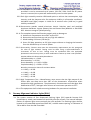
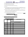
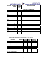
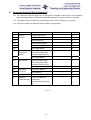
Paragraph Mandatory Required Comply Documents Attached (YES or NO) To be filled by the Responder 3.3 3.4 3.5 4.1 4.2 5.1 + + + 5.2 + 5.3 5.4 5.5 5.6 + 5.7 5.8 + 5.9 + 5.10 + 5.11 5.12 5.13 7.2 Reference List The Responder shall provide full information for at least 2 projects Description Lead‐in Flasher Lead‐in Solar Array
Lead‐in Battery
Lead In Wireless Control RAIL Flasher Solar
RAIL Wireless Control
REIL Flasher Solar REIL Wireless Control
Wireless Hand Controller
Quantity Airport Heliport 8
Month Year Remarks/ Contact Ref. 8.
Responder Proposal (Bill of Quantities) 8.1 The responder shall fill details for all equipment included in each item in the following table including listing of additional required equipment if not mentioned in the table. 8.2 Final quantities are subject to customer discretion, with no change in unit price. 8.3 All prices include User Manual (3 hard copies + Digital Data). Item Title Equipment Included Model Qty. 1.1 3 Lights (LED) Assy. 6 Solar Panel 6 1.3 Battery Box Assy. 6 1.4 Power & Control Box 6 1.5 Interconnecting Cables 6 1.6 Spare Light Head 3 Chassis, Flasher Head, GPD, Radio, Mounting hardware, Battery Assy. 6 Spare Light Head 1 Chassis, Flasher Head, GPD, Radio, Mounting hardware, Battery Assy. 2 Spare Light Head 1 Controller, Battery 1 4.2 Handheld Controller 5 Training 6 Optional Travel, Assistance in Commissioning Installation, Commissioning and start up 1.2 2.1 Lead‐In Barrette RAIL Sequenced Flasher 2.2 3.1 REIL Flasher 3.2 4.1 Spare Battery ******* 9
‐‐‐ 1 1 ‐‐‐ 1