1
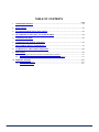
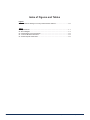
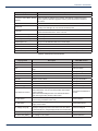
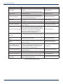
SM
by
Status Monitoring
And Control Solutions
(HMS Compliant, SNMP Based)
SMACSM PCR Pilot Carrier Redundancy Platform
Installation & Operation Manual
Although every effort has been taken to ensure the accuracy of this document it may be necessary, without notice, to make amendments or correct omissions.
Specifications subject to change without notice.
SMACSM is a service mark of ATX in the United States and/or other countries. Products or features contained herein may be covered by one or more U.S. or foreign patents. Other non-ATX product and
company names mentioned in this data sheet are the property of their respective companies.
TABLE OF CONTENTS
Page
1. OPERATIONAL DETAILS.......................................................................................................................... 1-1
2. INSTALLATION.......................................................................................................................................... 2-1
3. SETTING REDUNDANT OSCILLATOR LEVELS...................................................................................... 3-1
4. SET THRESHOLDS & SET SOFT OSC ATTEN DB DELTA..................................................................... 4-1
5. CONFIGURATION MENU........................................................................................................................... 5-1
6. CONNECTION FOR NORMAL OPERATION............................................................................................. 6-1
7. REPLACEMENT MODULE ORDERING INFO.......................................................................................... 7-1
8. CALIBRATION OF SMAC-PCR RF DETECTORS.................................................................................... 8-1
9. MONITORING............................................................................................................................................. 9-1
9.1.
Connecting the Ethernet or Modem Communications Interface....................................................... 9-1
9.2.
Software Connection of Ethernet or Modem Communications Interface......................................... 9-1
10. SERVICE & SUPPORT............................................................................................................................. 10-1
10.1.
Contact ATX Networks.................................................................................................................... 10-1
10.2.
Warranty Information...................................................................................................................... 10-1
SMACSM - PCR Pilot Carrier Redundancy Platform – Installation & Operation Manual i
Index of Figures and Tables
Figures
#1 PC’s Network Settings for Factory Default UPS IP Address....................................9-2
Tables
#1 Specifications..........................................................................................................1-1
#2 Block Diagram.........................................................................................................1-2
#3 Administration Level Parameters.............................................................................9-2
#4 Common Module Parameters..................................................................................9-3
#5 Module Specific Parameters....................................................................................9-4
ii SMACSM - PCR Pilot Carrier Redundancy Platform – Installation & Operation Manual
CHAPTER 1: OPERATIONAL DETAILS
OPERATIONAL DETAILS
1.
Operational Details
•
Detects the failure of up to two system pilot carriers and reinserts internal replacement oscillator.
•
Reinserts replacement oscillator at two different output levels depending on the reduced level or complete failure of
the system pilot carrier.
•
Monitor and control of all functions through front panel or over the data network (HMS compliant, SNMP v2c) or Web
browser.
•
Phase Lock Loop (PLL) controlled, low spurious oscillators.
•
LCD display shows the current alarms and allows detector thresholds to be set.
•
Independent removable and replaceable AC power supplies provide full power redundancy.
•
Compact 1RU chassis.
•
Simple two-cable connection.
•
Suitable for headend and hubsite applications.
•
Front panel test points for oscillator levels and combined full system output level monitoring.
•
Field upgradeable and swappable pilot carrier filters and replacement oscillators.
Table #1: Specifications
SMACSM - PCR Pilot Carrier Redundancy Platform – Installation & Operation Manual 1-1
CHAPTER 1: OPERATIONAL DETAILS
RF OUT
RF IN
RF PILOT
DETECTOR
BANDPASS
FILTER
RF PILOT
DETECTOR
BANDPASS
FILTER
-20 dB
OUTPUT TP
NETWORK
CONNECTION
MONITOR AND CONTROL
RJ-45
OSC
DETECTOR
CRYSTAL
OSCILLATOR
ATT
OSC A
INDEPENDENT
+24 VDC
POWER
SUPPLY
INDEPENDENT
+24 VDC
POWER
SUPPLY
OSC A TP
OSC
DETECTOR
CRYSTAL
OSCILLATOR
OSC B TP
ATT
OSC B
SMAC – PCR Pilot Carrier Redundancy Switch
Table #2: Block Diagram
1-2 SMACSM - PCR Pilot Carrier Redundancy Platform – Installation & Operation Manual
CHAPTER 2: INSTALLATION
INSTALLATION
2.Installation
•
Rack-mount the SMAC-PCR unit into your 19” equipment rack using a minimum of two 10 x 32 machine screws in
the bottom two holes on the PCR chassis.
•
Interrupt the Cable System feed and ‘splice’ in the SMAC-PCR using the Rear Panel RF IN and RF OUT
connectors.
•
Connect two IEC 3-prong power cords between each of the two rear panel Power Supply jacks and two 120 VAC
electrical outlets. For testing purposes, only one is required to be connected.
•
The front panel LCD display should quickly flash the ATX Networks splash screen and then show the Status
Summary screen indicating the status of the two internal Oscillators, the status of the two System Pilot Carriers and
the status of the two DC Power Supplies.
•
The Pilot A & B, the OSC A & B and PS A & B should not be flashing to indicate that the Oscillators and Power
supplies are in good working order and that the SMAC-PCR is detecting your system pilots.
SMACSM - PCR Pilot Carrier Redundancy Platform – Installation & Operation Manual 2-1
CHAPTER 2: INSTALLATION
This page left intentionally blank.
2-2 SMACSM - PCR Pilot Carrier Redundancy Platform – Installation & Operation Manual
CHAPTER 3: SETTING REDUNDANT OSCILLATOR LEVELS
SETTING REDUNDANT OSCILLATOR LEVELS
3.
Setting Redundant Oscillator Levels
•
Using a spectrum analyzer or signal level meter, measure the current RF level of the two system pilot carriers by
monitoring the SMAC-PCR –20 dB OUTPUT TP connector.
•
Navigate to the ‘SET-UP MENU’ using the UP/DOWN arrows. Navigate to the ‘SET OSC MODE’ Menu using
the LEFT/RIGHT arrows. From here you can enable or disable either of the SMAC-PCR oscillators as desired.
NOTE: this will not have any effect on the existing pilot carriers of the system, only whether or not the internally
generated carriers will be available.
•
Adjust system amplifier to compensate for the added loss of the SMAC-PCR.
•
Navigate to the ‘SET-UP MENU’ using the UP/DOWN arrows. Navigate to the ‘Press Enter to Store RF Levels’ and
press Enter to begin an auto-calibration routine, which does the following:
a) Samples existing pilot carrier RF levels at the pre-determined frequencies
b) Stores these levels as the threshold for normal operation
c) Adjust internally generated oscillators to match pilot carrier levels
•
This platform is designed such that no further set-up is required. However, if the default values are not desired, the
following options are available.
SMACSM - PCR Pilot Carrier Redundancy Platform – Installation & Operation Manual 3-1
CHAPTER 3: SETTING REDUNDANT OSCILLATOR LEVELS
This page left intentionally blank.
3-2 SMACSM - PCR Pilot Carrier Redundancy Platform – Installation & Operation Manual
CHAPTER 4: SET THRESHOLDS & SET SOFT OSC ATTEN DB DELTA
SET THRESHOLDS & SET SOFT OSC ATTEN DB DELTA
4.
Set Thresholds & Set Soft OSC Atten DB Delta
•
Navigate to the ‘SET-UP MENU’ using the up/down arrows. Navigate to the ‘Set Thresholds’ Menu using the LEFT/
RIGHT arrows. Set the Soft, Hard and Hysteresis Threshold values as required.
•
Navigate to the ‘SET-UP MENU’ using the up/down arrows. Navigate to the ‘Set Soft Osc Atten’ Menu using the
LEFT/RIGHT arrows. Set the Soft Osc Atten dB delta value as required.
a) Sft = Soft Fail Threshold – If either pilot drops this dB value below the calibrated set-point, the SMAC PCR
enters soft fail for this frequency and will insert a CW carrier at the same frequency. The inserted carrier will
be at a lower power than the calibrated level. This value is set at ‘Soft Osc Atten dB Delta’ in the LCD menu
(default of 3 dB).
b) Hrd = Hard Fail Threshold – If either pilot drops this dB value below the calibrated set-point, the SMAC-PCR
enters hard fail for this frequency and will insert a CW carrier at the same frequency, at the same power level
that the pilot carrier was at when the calibration was performed.
c) Hys = Hysteresis – If the pilot enters a soft or hard fail condition, the pilot level must return to at least this
many dB above the threshold in order for the fail condition to be reset.
Example: The calibrated pilot level is 40 dBmV, Sft = 5, Hrd = 10, Hys = 3, dB delta = 3
•
Once pilot drops below 35 dBmV it enters soft fail mode and SMAC-PCR injects a 37 dBmV CW carrier.
•
If the pilot then drops to 30 dBmV, the injected carrier rises to 40 dBmV.
•
Once the pilot carrier power returns to 33 dBmV the injected carrier drops back to soft fail level of 37 dBmV.
•
The pilot then must drop below 30 dBmV to re-enter hard fail mode, or rise to 38 dBmV to re-enter normal operation
and turn off the injected carriers.
SMACSM - PCR Pilot Carrier Redundancy Platform – Installation & Operation Manual 4-1
CHAPTER 4: SET THRESHOLDS & SET SOFT OSC ATTEN DB DELTA
This page left intentionally blank.
4-2 SMACSM - PCR Pilot Carrier Redundancy Platform – Installation & Operation Manual
CHAPTER 5: CONFIGURATION MENU
CONFIGURATION MENU
5.
Configuration Menu
•
By pressing F1 or F2 you can return to the Status Summary screen on the front panel LCD display.
•
Using the UP/DN arrows on the SMAC-PCR front panel, navigate to the CONFIGURATION screen.
•
Press the RIGHT arrow to see the Configuration settings.
•
You can use the UP/DN arrows in the Configuration settings menu to navigate the following:
o
Display Brightness
o
Network Settings
•
The first three items are self-explanatory and relate to the LCD display. The last menu item allows you to change the
network settings of the device.
•
To change the Network Settings use the UP/DN arrows in the Configuration settings menu to navigate to Network
Settings and then press the Front Panel ENTER button.
•
This will bring you to the Enter IP address screen. Use the RIGHT/LEFT arrows to select the digit for editing and UP/
DOWN arrows to edit the number. Press ENTER when completed.
•
This will bring you to the Enter MASK screen. Use the RIGHT/LEFT arrows to select the digit for editing and UP/
DOWN arrows to edit the number. Press ENTER when completed.
•
This will bring you to the Enter GATEWAY screen. Use the RIGHT/LEFT arrows to select the digit for editing and UP/
DOWN arrows to edit the number. Press ENTER when completed.
SMACSM - PCR Pilot Carrier Redundancy Platform – Installation & Operation Manual 5-1
CHAPTER 5: CONFIGURATION MENU
This page left intentionally blank.
5-2 SMACSM - PCR Pilot Carrier Redundancy Platform – Installation & Operation Manual
CHAPTER 6: CONNECTION FOR NORMAL OPERATION
CONNECTION FOR NORMAL OPERATION
6.
Connection for Normal Operation
•
The Pilot A & B, the OSC A & B and PS A & B should not be flashing to indicate that the Oscillators and Power
supplies are in good working order and that the SMAC-PCR is detecting your system pilots.
•
If the Pilot A or B character is slowly flashing, this indicates a soft fail. Fast flashing indicates a hard fail. All other
indicators have only fast flashing to indicate failure. PS failure is based on voltage dropping below 22V and OSC
failure will occur if the oscillator cannot produce an acceptable carrier.
•
Although the redundant oscillators are not inserted into the system during normal operation, you can verify those
redundant oscillator levels using the front panel –20 dB test points. These test points are in relation to the SMACPCR RF output.
•
You can monitor your system, including your system pilots and any inserted redundant oscillators as a result of
system pilot failure, at the –20 dB system test point.
SMACSM - PCR Pilot Carrier Redundancy Platform – Installation & Operation Manual 6-1
CHAPTER 6: CONNECTION FOR NORMAL OPERATION
This page left intentionally blank.
6-2 SMACSM - PCR Pilot Carrier Redundancy Platform – Installation & Operation Manual
CHAPTER 7: REPLACEMENT MODULE ORDERING INFO
REPLACEMENT MODULE ORDERING INFO
7.
Replacement Module Ordering Info
The following modules can be ordered if the system pilot frequencies change in your system. The chassis must be de-racked
to change the Pilot bandpass filter and redundant oscillator. The power supplies are replaceable while the chassis is in the
rack.
Part Number
PCR-SW-xx/yy
PCR-SW-xx
PCR-SW-DC-xx/yy
PCR-SW-DC-xx
PCR-OSC-xx
PCR-NBP-xx
PCR-PS
PCR-PSV0
PCR-PS-DC
Description
SMAC-PCR Two Pilot Redundancy Switch (xx/yy = pilot frequencies in MHz) AC Power
SMAC-PCR One Pilot Redundancy Switch (xx = pilot frequency in MHz) AC Power
SMAC-PCR Two Pilot Redundancy Switch (xx/yy = pilot frequencies in MHz), -48 VDC Power
SMAC-PCR One Pilot Redundancy Switch (xx = pilot frequency in MHz), -48 VDC Power
SMAC-PCR Replacement Oscillator (xx = oscillator frequency in MHz)
SMAC-PCR Replacement Narrow Bandpass Filter (xx = filter centre frequency in MHz)
SMAC-PCR Replacement Power Supply Module, AC Power
SMAC-PCR Replacement Power Supply Module for Legacy SMAC Units
SMAC-PCR Replacement Power Supply Module, -48 VDC Power
NOTES:
Items 5 & 6 can be ordered separately as back-up devices for the existing modules in the SMAC-PCR-SW.
Items 5 & 6 are required when the customer needs to change the frequency of one or both of the oscillators.
Items 5 & 6 must be ordered together and must have the same frequency for the PCR Switch to operate properly.
SMACSM - PCR Pilot Carrier Redundancy Platform – Installation & Operation Manual 7-1
CHAPTER 7: REPLACEMENT MODULE ORDERING INFO
This page left intentionally blank.
7-2 SMACSM - PCR Pilot Carrier Redundancy Platform – Installation & Operation Manual
CHAPTER 8: CALIBRATION OF SMAC-PCR RF DETECTORS
CALIBRATION OF SMAC-PCR RF DETECTORS
8.
Calibration of SMAC-PCR RF Detectors
•
If the pilot detection levels or inserted carrier levels are more than 1 dB off expected values, then a re-calibration
may be necesssary. (Likely, this will never need to be performed)
•
Use the LCD to navigate to the Configuration menu, and then to the “Revision = …”
•
Press the following key combination: Enter, Left, Right, Enter
•
The display should now say “Press Enter to Cal…”, press Enter
•
The display instructs you to set Pilots to 35 dBmV, so apply a known 35 dBmV CW pilot at both pilot frequencies
desired using an external signal source or Matrix Generator to the RF IN port. Connect a Spectrum Analyzer at the
RF OUT port. Press Enter when ready. The unit will sample each pilot carrier and slightly adjust it’s readings to now
give an accurate pilot detection level.
•
Terminate the RF IN port as instructed by the LCD.
•
Set the Spectrum Analyzer to view the inserted A frequency carrier and use the UP/DN LCD arrows to adjust the
inserted carrier until it gets as close to 33 dBmV without going over. Press Enter when done and repeat for the B
frequency.
•
Calibration is complete.
SMACSM - PCR Pilot Carrier Redundancy Platform – Installation & Operation Manual 8-1
CHAPTER 8: CALIBRATION OF SMAC-PCR RF DETECTORS
This page left intentionally blank.
8-2 SMACSM - PCR Pilot Carrier Redundancy Platform – Installation & Operation Manual
CHAPTER 9: MONITORING
MONITORING
9.Monitoring
9.1.
Connecting the Ethernet or Modem Communications Interface
To use this feature, the Network Communication Interface board PN# 10569 (Ethernet adaptor) option must have been
installed when the unit was ordered. This can be confirmed by looking at the Left Hand Side of the internal cover panel to
see if an Ethernet port is present.
The Comm Interface is monitored by Ethernet or via a customer-supplied cable modem. (An RS485 interface will be available
on quantity special order, to communicate via a DOCSIS transponder.)
1. Connect the Power Supply Input for the modem, to the 12V terminals using the 3 terminal connector provided. The
bottom connection is ground (negative) and the middle is +12 VDC.
2. Connect the Ethernet patch cable between the Ethernet port and the modem. Alternatively use a crossover cable to
go directly between Ethernet port and a PC for initial set-up.
3. Connect the RF coaxial cable between the modem and the F81 terminal on the LHS of the inner panel.
9.2.
Software Connection of Ethernet or Modem Communications Interface
By default the device ships with a static IP address of 192.168.0.1 If at any time the user chooses to revert back to the factory
defaults, the reset button (located near the RJ45 port) must be held down for approx 10 seconds until the LED turns off. When
the device reboots, it will have default passwords and IP address.
In order to connect to a device, the PC must be on the same subnet as the device. Open your Windows Network Connections
on the Control Panel. Right click your local area connection, then select Internet Protocol (TCP/IP) and click on Properties.
Select ‘Use the Following IP address’ and enter the values shown to the right.
Now you can open any web browser and enter 192.168.0.1 in the URL field. A logon page will appear, at which point you can
log in as Administrator with the password of administrator. From here you can change the login password, upgrade the
firmware of the device, or set the communication parameters.
Select DHCP if you choose to use your network’s DHCP server to provide an IP address, or choose static IP and assign a
unique, unused IP that is part of your system’s subnet.
Enter in a list of IP addresses for trap recipients. These will be the computers that will be sent SNMP traps in the event of any
alarm. Likewise you can enter a list of email addresses to receive a similar alarm message if you don’t have SNMP monitoring
software. Consult your IT department for the outgoing mail server information required.
SMACSM - PCR Pilot Carrier Redundancy Platform – Installation & Operation Manual 9-1
CHAPTER 9: MONITORING
Note that all SNMP traps and emails shall include the Alias (entPhysicalAlias) of the device which is alarming. This is a user
configurable text field that many customers use to identify the specific device (i.e. Nodes serviced, room or rack location, etc).
This value is set using any SNMP manager software. See the next page.
Figure #1: PC’s Network Settings for Factory Default UPS IP Address
9-2 SMACSM - PCR Pilot Carrier Redundancy Platform – Installation & Operation Manual
CHAPTER 9: MONITORING
Display Name
Description
Hostname/ Domain Name
Optional Fields
Define the static IP address of the chassis. This address is maintained during
IP Address, Subnet Mask, Default
power cycles and firmware upgrades. A factory reset will revert the IP back to
Gateway
192.168.0.1
DNS Servers
Enter the domain name server to be able to enter www... URL’s into any fields
NTP Server
If there is no network time server available leave this blank. All times are then
counting from midnight, Jan 1st, 1970 as the start-up time
Time Zone
Only used if NTP server used. Adds local time zone offset to UTC time. e.g. for
Eastern Standard Time Zone, enter ‘UTC+5:0’
Read-write Community Name
SNMP Required Variable
Read-only Community Name
SNMP Required Variable
Default Trap Community Name
SNMP Required Variable
Trap Recipient List
List up to 10 IP addresses that are to receive traps.
System Name, Location, Contact
Optional SNMP Fields
SMTP Server
Mail Server
Email Recipient List
List up to 5 email addresses that are to receive an email form of the traps.
SMTP Username, Password
If authentication required, must enter an email user name and password.
Table #3: Administration Level Parameters
Display Name
Description
HMS MIB Variable
Description
Description of the module
entPhysicalDescr
Name
Indicates the chassis slot of the module
entPhysicalName
Alias
Optional user defined field - added to fifth variable binding of
traps
entPhysicalAlias
Manufacturer
ATX
entPhysicalMfgName
Model
ATX model number
entPhysicalModelName
Asset I.D
Optional user defined field
entPhysicalAssetID
Serial No
Module’s serial number
entPhysicalSerialNum
Hardware Rev
Hardware rev of module
entPhysicalHardwareRev
Firmware Rev
Firmware rev of module
entPhysicalFirmwareRev
Temperature [C]
Module’s current temperature
heCommonTemperature
Alarm Detection Control
detectionEnabled: normal operation, with active alarms
detectionDisabled: used to temporarily disable alarms/traps
from this module
detectionEnabledandRegenerate: enter detectionEnabled
state while regenerating all alarm table entries
heCommonAlarmDetectionControl
Fan Unit Status
Alarm status of the fan (Currently there is no need for fans,
so this is only provided for future use)
heFanUnitAlarm
P.S. Description
Description of the voltage supplied to the internal power
supply of the module
hePsUnitDescription
P.S. Voltage Out [Volt]
Unit measures both 24V inputs from the redundant supplies.
Displayed voltage and power is the lesser of the two values.
hePsUnitVoltageIN
If either PS fails, the voltage displayed will be the failed value.
P.S. Current Out [mA]
Current supplied to the unit from the combined 24V supplies
hePsUnitCurrentIN
P.S. Power Out [Watts]
P.S. Voltage * P.S. Current
hePsOutputPower
Table #4: Common Module Parameters
SMACSM - PCR Pilot Carrier Redundancy Platform – Installation & Operation Manual 9-3
CHAPTER 9: MONITORING
Display Name
Description
HMS MIB Variable
RF Sw Mode
automatic: switching based on threshold (recommended)
manual: switch forced to RF/Opt Sw Control side
heRFSwitchMode
RF Sw Control
Default side of switch (PathA = Pilot (recommended)
or PathB =TSG only)
heRFSwitchControl
RF Sw Revert Enable
on (recommended): switch will revert back if pilot
carrier power is restored (also, must be in automatic
mode and hysteresis accounted for)
heRFSwitchRevertEnable
RF Sw State
Active path of the switch (PathA = Pilot or PathB =
TSG only)
heRFSwitchState
RF Sw Fail-Over Status
Fault if RF Sw Control not equal to RF Sw State
heRFSwitchFailoverStatus
RF Sw Both Input Status
Fault if either switch input is below RF Sw Input
Power Threshold
heRFSwitchBothInputStatus
RF Sw Input Hysteresis [dB]
Only values >= 0 are acceptable. e.g. If 2 dB , TSG
turns on if pilot carrier levels drops below threshold,
but does not turn off until pilot carrier level increases
to threshold + 2 dB (*must also be in automatic
mode, revert-enable on and wait to restore time
expired). Recommended Value of 3 dB
heRFSwitchHysteresis
RF Sw Wait to Restore Input
Time [sec]
Time-based hysteresis. Same principle as above, but
time delayed switch restore. Recommended value of
1s
heRFSwitchWaitToRestoreTime
Pilot Carrier Input Level
[dBmV]
Measured input level of switch
heRFSwitchInputRFLevel
Pilot Carrier OFF Threshold
[dBmV]
User defined switch threshold (linked to RF Input
Power LOLO alarm threshold) Recommended 4 dB
below LO threshold
heRFSwitchSetInputPowerThreshold / analogAlarmLOLO
RF Sw Input Power LO
alarm threshold (only settable on analog properties
page)
Defines the threshold of a low-level pilot carrier, at
which point the Redundant carrier first turns on, at
a lower level defined at the LCD interface. Recommended 4 dB below nominal pilot level.
analogAlarmLO
RF Sw Output Description
Description of the output – a reminder of what the
switch state means
heRFSwitchOutputDescription
TSG Output Description
“Redundant Carrier A” a.k.a TSG output
heRFAmpOutputDescription
TSG Output Level [dBmV
The level of the redundant TSG carrier at the output
of the device (after attenuation, switch, couplers)
heRFAmpOutputLevel
TSG Output Attenuator
Control [dB]
A means to vary the drive level of the redundant
carriers by attenuating the source.
heRFAmpOutputAttenuatorControl
Table #5: Module Specific Parameters
9-4 SMACSM - PCR Pilot Carrier Redundancy Platform – Installation & Operation Manual
SMACSM - PCR Pilot Carrier Redundancy Platform – Installation & Operation Manual CHAPTER 9: MONITORING
9-5
CHAPTER 9: MONITORING
This page left intentionally blank.
9-6 SMACSM - PCR Pilot Carrier Redundancy Platform – Installation & Operation Manual
CHAPTER 10: SERVICE & SUPPORT
SERVICE & SUPPORT
10. Service & Support
10.1. Contact ATX Networks
Please contact ATX Technical Support for assistance with any ATX products. Please contact ATX Customer Service to obtain
a valid RMA number for any ATX products that require service and are in or out-of-warranty before returning a failed module
to the factory.
TECHNICAL SUPPORT
Tel: (905) 428-6068
Toll Free: (800) 565-7488 (USA & Canada only)
► Press *3 for Technical Support
► Then press 1 for Digital Video Products (DVIS, DigiVu, UCrypt, etc.)
► OR, press 2 for All Other Products
Email: [email protected] for Digital Video Products
Email: [email protected] for All Other Products
CUSTOMER SERVICE
ATX Networks
1-501 Clements Road West
Ajax, ON L1S 7H4 Canada
Tel: (905) 428-6068
Toll Free:
(800)565-7488 (USA & Canada only)
► Press *1 for Customer Service
Fax: (905) 427-1964
Toll Free Fax: (866) 427-1964 (USA & Canada only)
Web: www.atxnetworks.com
Email: [email protected]
10.2. Warranty Information
All of ATX Networks’ products have a 1-year warranty that covers manufacturer’s defects or failures.
SSMACSM - PCR Pilot Carrier Redundancy Platform – Installation & Operation Manual 10-1
1-501 Clements Road West, Ajax, ON L1S 7H4 Canada
Tel +1 (905) 428-6068 Toll Free +1 (800) 565-7488
Fax +1 (905) 427-1964 Toll Free Fax +1 (866) 427-1964
www.atxnetworks.com [email protected]
Printed in Canada
Rev. 07/23/15 (ANW0796)