1
4
cap screw through the hole and through the ½ inch spacer and then tighten the cap
screw into the anchor.
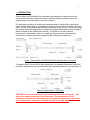
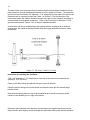
2.2.1. Installation using Weldable Fixtures
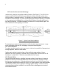
Figure 4 - Installation using Weldable Fixtures
Installation instructions;
(See section 2.2 for special instructions re Models 4420-1-12 and 4420-1-25)
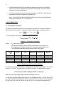
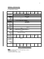
1. Determine proper setting distance using figures in Table 1 or the readings on the
calibration sheet. Prepare the surface (grinding, sanding, etc.) of the steel around
the area of each weldable fixture.
2. Locate the welding fixtures on prepared surfaces, check spacing again and tack weld
to the member.
3. Remove the nylon tie securing the transducer shaft. Thread the cap screw through
the swivel bearing and through the ½ inch spacer on each end. Then tighten the cap
screws into the welding fixtures.
4. Check the reading with a portable readout. Use Table 2 or the readings on the
calibration sheet to check the position. The installation is now complete.
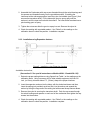
2.2.2. Installation using Groutable Anchors
Figure 5 - Installation using Groutable Anchors
Installation instructions;
(See section 2.2 for special instructions re Models 4420-1-12 and 4420-1-25)
1. Determine proper setting distance using figures from Table 1 or the readings on the
calibration sheet. Using a hammer drill or other suitable equipment, drill two ½"
holes approximately 3" deep at the proper locations. Shorter holes may be drilled if
the anchors are cut down accordingly.