1
3
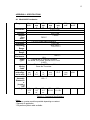
Model & Range
Mid-Range
4420-12 mm
4420-.5"
4420-25 mm
4420-1"
4420-50 mm
4420-2"
4420-100 mm
4420-4"
4420-150 mm
4420-6"
4420-200 mm
4420-8”
4420-300 mm
4420-12
325 mm
12.8"
333 mm
13.1"
406 mm
16”
543 mm
21.4"
686 mm
27.0"
740 mm
29.1”
967 mm
38.1"
To Monitor
Extensions
319 mm
12.6"
321 mm
12.6"
381 mm
15”
493 mm
19.4"
611 mm
24.1"
640 mm
25.2”
817 mm
32.2"
To Monitor
Compressions
331 mm
13.0"
345 mm
13.6"
432 mm
17"
593 mm
23.3"
761 mm
30.0"
840 mm
33.1”
1117 mm
44"
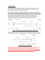
Table 1 - Crackmeter Anchor Spacing Distances
When setting the gage position using a portable readout (see section 3) use the reading
ranges in Table 2 to determine the proper position.
Approx Mid-Range
Approx Reading to
Approx Reading to
Reading
Monitor Extensions Monitor Compressions
4500-5000
2500-3000
6500-7000
Table 2 - Crackmeter Reading Ranges
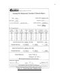
Note also that the calibration sheet (Figure 8) supplied with the Crackmeter shows actual
readings at zero, 25%, 50%, 75% and 100% of the range of extension. These readings can
be used as a guide to set the Crackmeter in any part of it's range, either in anticipation of
closure or opening of the crack. The Crackmeter can be extended until the desired reading
(see Section 3 for readout instructions) is obtained and then held in this position while the
distance between the anchor points (threaded cap screws inside the swivel bearings), see
Figure 1) is measured. This measurement can then serve as a spacing guide for drilling or
welding the anchor points.
Caution: Do not rotate the shaft of the Crackmeter. This may cause irreparable
damage to the instrument. The alignment pin on the transducer shaft and slot on the
body serve as a guide for alignment.
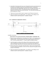
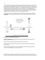
Special note regarding installation of the Model's 4420-1-12 or 4420-1-25: If the
reading is not in the proper range after installation additional adjustment is provided
for by the inclusion of a threaded extension and locking nut as depicted in Figure 2.
In order to use this feature the transducer needs to be attached, at the coil assembly
end, to the anchor. Position (but do not attach) the opposite end of the Crackmeter
over the threaded hole of the anchor. If the reading is not in the proper range (see
Table 2) loosen the locking nut (Figure 2) and rotate the threaded rod which carries
the rod end swivel bearing, in or out of the end of the Transducer Shaft until the
desired spacing and initial reading has been achieved. The transducer shaft itself
must not be rotated. It should be gripped while rotating the rod end swivel bearing.
After adjusting, align the hole in the rod end swivel bearing over the anchor, place the