1
5
2. Assemble the Crackmeter with cap screws threaded through the swivel bearings and
the spacers and threaded loosely into the groutable anchors. If installing the
instrument at the mid-range position, leave the nylon tie installed (see Figure 1) that
secures the transducer shaft. Fill the holes with grout or epoxy and push the
anchors in until the tops are flush with the surface. For holes drilled overhead use a
quick setting grout or epoxy.
3. Tighten the set screws after the grout or epoxy has set. Remove the nylon tie.
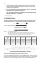
4. Check the reading with a portable readout. Use Table 2 or the readings on the
calibration sheet to check the position. Installation complete.
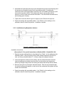
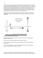
2.2.3. Installation using Expansion Anchors
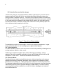
Figure 6 - Installation using Expansion Anchors
Installation instructions;
(See section 2.2 for special instructions re Models 4420-1-12 and 4420-1-25)
1. Determine proper setting distance using figures from Table 1 or the readings on the
calibration sheet. Using a masonry drill or other suitable equipment, drill two 3/8
inch, (or 10mm), diameter holes 1¼", (32mm), deep at the proper locations.
2. Insert the expansion anchors into the holes, with the slotted end down and then,
insert the setting tool provided, small end first, into the anchor and expand the
anchor by hitting the large end of the setting tool with several sharp hammer blows.
3. Remove the nylon tie securing the transducer shaft. Push the cap screws through
the swivel bearings and spacers on each end of the crackmeter then tighten the cap
screws into the anchors.
4. Check the reading with a portable readout. Use Table 2 or the readings on the
calibration sheet to check the position. Installation complete.