1
重要申明
BIOCAM Series Products User Manual
Version: V1.2
Date: July 2014
About This Manual
This document introduces the user interface and menu operations of the BIOCAM series products.
For the installation of the device, see BIOCAM Series Products Installation Guide.
1
Important Claim
Important Claim
Firstly, thank you for purchasing this terminal, before use, please read this manual carefully to avoid the unnecessary
damage! The company reminds you that the proper user will improve the use affect and authentication speed.
No written consent by our company, any unit or individual isn’t allowed to excerpt, copy the content of this manual in part
or in full, also spread in any form.
The product described in the manual maybe includes the software which copyrights are shared by the licensors including
our company, Except for the permission of the relevant holder, any person can’t copy, distribute, revise, modify, extract,
decompile, disassemble, decrypt, reverse engineering, leasing, transfer, sub-license the software, other acts of copyright
infringement, but the limitations applied to the law is excluded.
To learn more, please visit our website www.zkivision.com or local office.
Due to the constant renewal of products, the company cannot undertake the actual product in
consistence with the information in the document, also any dispute caused by the difference
between the actual technical parameters and the information in this document. Please forgive any
change without notice.
Warning: This is a class A product. In a domestic environment this product may cause radio
interference in which case the user may be required to take adequate measures.
i
BIOCAM Series Products User Manual
Contents
1 Instruction for Use ................................................................................................................................ 1
1.1 The Distance, Facial Expression and Stand Pose ........................................................................ 1
1.2 Enrollment Pose ............................................................................................................................. 2
1.3 Verification Modes.......................................................................................................................... 3
1.4 Keys on the Remote Control .......................................................................................................... 4
2 Overview ................................................................................................................................................. 5
2.1 Product Description ........................................................................................................................ 5
2.2 Product Features............................................................................................................................ 5
2.3 Technical Parameters .................................................................................................................... 7
2.4 Product Appearance ...................................................................................................................... 9
2.5 Terminal Interface ........................................................................................................................ 10
2.6 Initial Interface .............................................................................................................................. 11
2.7 Basic Procedure ........................................................................................................................... 11
3 Installation and Network Configuration ............................................................................................ 12
3.1 Hardware Installation ................................................................................................................... 12
3.2 Network Connection ..................................................................................................................... 14
4. Main Menu ........................................................................................................................................... 15
5. Add User.............................................................................................................................................. 16
5.1 Enrolling Face .............................................................................................................................. 16
5.2 Enter User ID ............................................................................................................................... 16
5.3 Enrolling Card .............................................................................................................................. 17
5.4 Modify User Rights ....................................................................................................................... 17
6. User Management .............................................................................................................................. 18
6.1 Edit User....................................................................................................................................... 18
6.2 Delete User .................................................................................................................................. 18
6.3 Query User ................................................................................................................................... 18
7 Date/Time Setting ................................................................................................................................ 19
8 Access Control Setting ....................................................................................................................... 20
9. Communication Settings ................................................................................................................... 21
10. Wiegand Format ............................................................................................................................... 22
10.1 Wiegand Input ............................................................................................................................ 22
10.2 Wiegand Output ......................................................................................................................... 22
10.3 Wiegand 26-bits Description ...................................................................................................... 23
10.4 Wiegand 34-bits Description ...................................................................................................... 24
11 Auto Test ............................................................................................................................................ 25
12 System Settings ................................................................................................................................ 26
I
Contents
12.1 Face Setting ............................................................................................................................... 26
12.2 Keyboard Definitions .................................................................................................................. 27
12.2.1 Edit Shortcut Keys ............................................................................................................ 27
12.2.2 Auto Switch Setting........................................................................................................... 27
12.3 System Information .................................................................................................................... 29
12.3.1 Records Information ......................................................................................................... 29
12.3.2 Device Information ............................................................................................................ 29
13 Accessing the Device ....................................................................................................................... 30
13.1 Using a Web Browser ................................................................................................................ 30
13.2 Using a Mobile Device ............................................................................................................... 31
13.3 Using the Network Video Surveillance Software ....................................................................... 32
Appendix ................................................................................................................................................. 34
Appendix 1 Introduction to Wiegand .................................................................................................. 34
Appendix 2 How to achieving Attendance, Access and IPC ZKiVision function ............................... 34
Appendix 3 How to change IP Address for device ............................................................................ 35
Appendix 4 How to Sync time for IPC device .................................................................................... 36
Appendix 5 Statement on Human Rights and Privacy ...................................................................... 37
Appendix 6 Environment-Friendly Use Description ........................................................................... 38
II
BIOCAM Series Products User Manual
1 Instruction for Use
1.1 The Distance, Facial Expression and Stand Pose
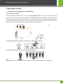
1. The recommended distance
Recommended horizontal distance from the user to Face Recognition Camera is about 3 meters. (applied to height
range 1.5~1.9 m). The area in which face recognition can be implemented is defined as follows: the left-to-right distance is
about 0.35 m, and the front-to-rear distance is about 1 m. The location of the face can be adjusted based on the effect of
the face image obtained by the device. When the face image is in the upper part of the video area, move the face forward.
When the face image is in the lower part of the video area, move the face backward.
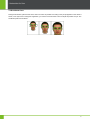
2. The recommended facial expression and several poor-effect facial expressions:
3. The recommded stand pose and several poor-effect stand poses:
1
Note: During the enrollment and verification, please remain the normal facial expression and stand pose.
1 Instruction for Use
1.2 Enrollment Pose
During the enrollment, place the face in the centre of screen as possible. According to the prompt appears on the device’s
screen, focus eyes in box. During face registration, you need to move from back to front to adjust the position of eyes. The
enrollment poses are as follows:
2
BIOCAM Series Products User Manual
1.3 Verification Modes
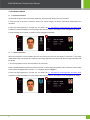
1: N Facial Verification
The terminal compares current face image collected by the camera with all face data on the terminal.
1. Place the face in the area in which the camera can capture images, the device automatically distinguishes face
verification.
2. Show the facial expression in a proper way. For details, see 1.1 The Distance, Facial Expression and Stand Pose.
Comparison of interface display the current image collected by the camera, an interface shown as Figure 1 will display.
3. If the verification is successful, an interface shown as Figure 2 will display.
1: 1 Facial Verification
When face recognition of a user is difficult, the user can punch the ID card on the card reader to access the 1:1 face image
authentication mode. The system will compare the face image captured by the camera with the face image associated with
the ID card.
1. Punch a registered ID card on the card reader in the correct way.
2. After card authentication is passed, the system enters the 1:1 face image authentication mode. At this time, the face image
on the interface is highlighted and a prompt "1:1" is displayed, shown as Figure 3.
3. Show the facial expression in a proper way. For details, see 1.1 The Distance, Facial Expression and Stand Pose.
Comparison of interface display the current image collected by the camera, an interface shown as Figure 4 will display.
3
1 Instruction for Use
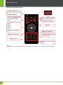
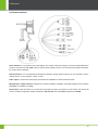
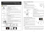
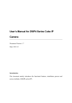
1.4 Keys on the Remote Control
Attendance Status Shortcuts.
For detail, please see 12.2
Keyboard Definitions.
Shortcut key for Add user when
unregistered administrator.
Input ":".
Press it to pop-up the Restart
Device prompt box, and then
reboot device as required.
: UP
: Down
Menu key
: Left
: Right
[OK]: Save and Confirm key
Return and Cancel key
Backspace and Delete key
Numeric Keys (0, 1, 2,
3, 4, 5, 6, 7, 8, 9)
[] key: Input ".".
[#] key: Press this key to input
space.
Tips: If the device is in dormant state, you can press any key on the remote controller to wake up the device.
4
BIOCAM Series Products User Manual
2 Overview
2.1 Product Description
The BIOCAM series integrates an attendance system, access system, and IP camera (IPC). It implements the attendance,
access, and video surveillance functions. This series of products is configured with a LCD, remote control (to facilitate
man-machine interaction and offline management), external peripheral Wiegand input, Wiegand Output, lock control, door
sensor, and LCD display to ensure that the device can independently complete all operations in offline status, including
extracting human faces, comparing and identifying human faces, and registering information. It is very highly safe and
practical.
Attendance Function
The BIOCAM series is a day/night embedded IPC that provides a face recognition based attendance function. This IPC is
embedded with the high-speed face recognition algorithm. It can extract, compare, and identify the face of whoever enters
the video area of the camera in real time. The video area is 2.5 m to 3.5 m away from the camera and is 2 m to 2.4 m high.
Access Function
The BIOCAM series integrates the security surveillance system with the intelligent video analysis system in the bottom
layer. With the intelligent analysis technology, the BIOCAM series screens out key information from massive video data
and provides the information to the administrators for further analysis and judgment. The embedded system mode not
only improves the stability of the device, but also substantially reduces the costs for implementing intelligent analysis. The
front-end high-speed recognition algorithm can analyze and process video streams on the device, which greatly reduces
the system delay and enhances the practicality. After the BIOCAM series is connected to an access control device, it can
extract and compare human faces to determine whether the door should be opened, closed, or whether an alarm should
be activated. The video surveillance function is linked with the access control function to implement the lock control
operations of the access control device.
Video Surveillance Function
The BIOCAM series adopts the mega-pixel CMOS sensor. The projection angle of the infrared lamp is wide, which
delivers outstanding night vision capability. The optimized H.264 coding algorithm ensures a clearer and smoother video
transmission effect. The embedded web server allows users to implement real-time monitoring and remote control on the
front-end camera by using a browser.
The BIOCAM series can be mounted on the wall or suspended. It is easy to install and convenient to operate. It is suitable
for indoor use. For example, it can be used for all-weather monitoring and face recognition in offices or banks where the
video surveillance, attendance, and access control systems are integrated.
The following describes how the attendance, access control, and video surveillance functions of the BIOCAM series are
implemented. Please see Appendix 2 How to achieving Attendance, Access and IPC Surveillance function.
2.2 Product Features
The mixed facial recognition algorithm features a large capacity and fast recognition speed. The product also
integrates two high-resolution infrared and color cameras.
5
The product integrates two high-resolution infrared and color cameras.
2 Overview
An ergonomic industrial design.
The infrared optical system is highly adaptive to the environment and can identify faces even at night.
The BIOCAM series in standard configuration is equipped with simple access control functions, including the door
sensor, door switch, lock control, Wiegand output and Wiegand input.
The BIOCAM series in standard configuration supports TCP/IP-based communication and searching across different
network segments or gateways.
The web server management mode is integrated with the PC software management mode to implement
management in a more flexible manner.
The BIOCAM series supports H.264 Main Profile.
Dual code stream, suitable for various networks
Support kinds of protocols, such as, TCP/IP, HTTP, TCP, UDP, ARP, SMTP, FTP, DHCP, DNS, DDNS, NTP,
ONVIF, RTSP, P2P and UPNP, etc.
The aluminum alloy die casting design is dust-proof and anti-corrosion effects.
Double-glass front cover for better optical isolation and mist prevention surface for better night viewing
Three-layer shield +magnetic ring design to eliminate signal interference
The dual-filter design supports the automatic night/day switch to achieve a better surveillance function.
Self-recovery from abnormality and auto reconnection after network interruption
Automatically capture images during an alarm and send them to the designated email
Supports motion detection
Allow setting several alarms and supports the remote alarm linkage
Network time synchronization (NTP)
The HD camera supports up to 10 users browsing at the same time, the total user of Main Stream and Second
Stream must less than 10
The dual CPUs support three cameras. One camera is used for surveillance, and the other two cameras are used for
face recognition.
The BIOCAM series has four embedded 850-nm large power infrared lamps. Two lamps are used for surveillance.
The irradiation distance is 8 m to 10 m. The other two lamps are used for face recognition.
The BIOCAM series supports infrared remote control. The maximum operation range of the remote control is 7 m
and the angle is 45º.
The 7-inch color LCD is used to display the user interface and face recognition results. Operations are convenient
and the interface is simple.
The BIOCAM series supports TF cards.
The BIOCAM series can generate voice to notify users of the face recognition and registration process and face
6
BIOCAM Series Products User Manual
recognition results.
The maximum Facial Capability is 400.
Mobile phone monitoring over the P2P protocol is supported; pushing facial recognition events to mobile terminals is
supported.
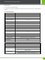
2.3 Technical Parameters
Function
IPC
Image Sensor
Megapixel HD COMS sensor
Image Resolution
Wide dynamic range and high definition 1280x720
Day/Night Switch
Double filter switch
Lens
M12 Interface 6mm
Minimum Illumination
1 Lux (IR lamp off);
0 Lux (IR lamp On)
IR Lamp
2 built-in 42 mil dot matrix infra-red lamps
Effective Projection Distance
8~10m
Effective Projection Angle
60°
Motion Detection
Detecting area that can be set to any shape
Function
Face Recognition
Image Resolution
Support 640×480
Face Recognition Algorithm
Face VX7.0
Camera
High-resolution infrared and color camera
IR
Two large-power infrared lamps that can be automatically turned on during face
recognition
Displayer
7-inch LCD that is used to display the image area of face recognition
Remote Control
Supports Numeric, "." and ":" input
Loudspeaker
Supports
Dormant function
Dormant function when no face image is detected
Audio
1 linear output
Records Capacity
100000
Facial Capacity
400
Function
Video Coding
Primary Processor
Hi3507
Operating System
Embedded Linux
Video Compression Algorithm
H.264 main profile level 3
Primary Code Stream: 720P:1536~10240kbps; D1:768~4096kbps adjustable
Video Compression Code Rate
Secondary Code Stream: D1:768~4096kbps; CIF:192~1024kbps;
QCIF:48~256kbps
Video Resolution
7
Primary Code Stream: 720P:1280x720;D1:704*576
Secondary Code Stream: D1:704*576;CIF:352*288;QCIF:176*144
2 Overview
Video Frame Rate
Video Parameters
PAL: 1~25 frames optional
NTSC: 1~30 frames optional
Brightness, Saturation, Contrast, Chroma, Gain, (Exposure, Image Up/Down,
Image Left/Right and Night Vision Mode) adjustable
Function
Functional Interfaces
Reset
Supports
Store
Network Interface
Access Control Interface
Supported Network Protocols
Supporting local storage by using TF cards, video recording, and photo shooting.
The maximum storage capacity is 32 GB.
10Base-T/100Base-TX Ethernet interface
Simple Access Control Function (Door Sensor, Exit Button, 3rd Party Electric
Lock, Wiegand Input, Wiegand Output)
TCP/IP, HTTP, TCP, UDP, ARP, SMTP, FTP, DHCP, DNS, DDNS,
NTP, UPNP, RTSP, ONVIF, P2P and so on.
Function
Working Environment
Input Power
DC 12V, ≥1.5A
Maximum Power Consumption
15W
Working Temperature
-10~ +50 ºC
Working Humidity
10 ~ 80%RH
Installation Mode
Wall-mounted, Ceiling mounted, Floor mounted
8
BIOCAM Series Products User Manual
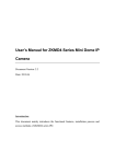
2.4 Product Appearance
Main View
850nm Large-power infrared lamps
IPC camera: Maximum Resolution
850nm Large-power infrared lamps
Dedicated camera for face recognition
7 inch LCD
Infrared receiver: Receives signals from the Remote Control.
Side View
Fixed Support
9
2 Overview
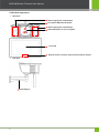
2.5 Terminal Interface
Power interface: It is connected to the power adapter. The voltage of the power supply for the device is DC 12V and the
current is not lower than 1.5A. (POE is also an optional power supply mode.) Do not use other power supplies; otherwise,
the camera may be damaged.
Network interface: It is a 10/100M self-sensing Ethernet interface, through which the device can be connected to various
network devices, such as switches, routers, or hubs.
Audio output: Connects with external play devices like act loudspeaker to utilize broadcast function.
Wiegand Input / Output Interface: Wiegand Input Interface (INWGD1, INWGD0, and GND); Wiegand Output Interface
(OUTWGD1, OUTWGD0, and GND).
Reset button: Press this button for more than 5 seconds after the device is powered on for 2 minutes; the camera will
recover to default configuration. Default IP address is 192.168.1.88, user name admin and password 123456.
10
BIOCAM Series Products User Manual
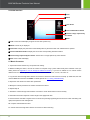
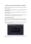
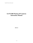
2.6 Initial Interface
① Time
② Week
③ User Photo
④ Current Attendance Status
⑤ Current image captured by
the camera
⑥ Date
① Time: Current time will display. Support 24-hour time systems only.
② Week: Current day is displayed.
③ User Photo: Display the photo that is automatically taken by the device after user authentication is passed.
④ Current Attendance Status: Display the current time corresponding attendance status.
⑤ Current image captured by the camera: Human face or image captured by other cameras.
⑥ Date: Current date will display.
2.7 Basic Procedure
1. Unpack and check whether any components are missing.
2. Before installing the device, connect the camera to computer using a patch cable. Modify the IP address of IPC (For
detail, please see Appendix 3 How to change IP Address for device). If your PC IP address is in a network section
different from IPC address, please set it to the same network section as IPC, such as, 192.168.1.87.
3. Log into the device through client software or browser to check if the video functions normally. (In initial state, the User
name is admin and Password is 123456. For detail, please see 13.1 Using a Web Browser.)
4. Adjust the code stream and other video parameters.
5. Modify the network parameters of camera and reboot the device.
6. Repeat Step 2.
7. Revisit the camera through client software or browser to check till the video functions normally.
8. Install the camera and adjust the camera angle to the appropriate area.
9. Use the remote controller to register users on the device (including registering human faces and cards and setting user
rights) and implement user management.
10. Compare and authenticate users.
11. Visit the camera through client software or browse for video monitoring.
11
3 Installation and Network Configuration
3 Installation and Network Configuration
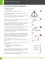
3.1 Hardware Installation
Installation Notices
1. Read through the guide for installation prior to installation.
2. Check whether any component is missing against the packing list, if yes,
please contacts your supplier.
3. Wire when the camera is powered off. If the camera does not function
normally during operation, please cut off the power before check.
Note: The wiring during power on may seriously damage the camera,
which will be disqualified from the guarantee.
4. Use the power supply of DC12V and no lower than 1.5A for the camera.
POE is also an optional power supply mode. Too high or low voltage, or AC
power supply may cause the abnormal operation of the camera.
5. Use the standard power cord when the power supply is too far away from
the camera, and consider the voltage drop caused by long distance.
6. Read through the instructions for connecting terminal and wire strictly
according to interfaces. Any damage to the camera due to improper operation
will be disqualified from the warrantee.
7. Mount the relay equipment in the middle to avoid signal attenuation when
the straight communication distance from the camera to the incoming
equipment exceeds 80m. (Remarks: under the POE [Optional] mode, if
transmission distance is greater than 60 meters, please use a repeater.)
8. Use the camera in the working conditions:
Ambient temperature: -10 ºC ~ +50 ºC; Ambient relative humidity: 10% ~
80%RH.
9. Keep the cleanness of double glasses in front of lens. If too dirty, clean
them with soft fabric.
Installation procedure for BIOCAM Series Products
Wall Mounting
1. Attach the installation template to the wall where you want to mount the
camera and drill holes. (It is recommended to install the device at a height of
2.2 m; according to needs, you can adjust it to 2~2.4 meters.)
2. Fix the camera on the wall using four screws. (The device can be rotated
left to right so that screws can be conveniently fastened.)
12
BIOCAM Series Products User Manual
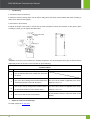
Top Mounting
1. Connect the steeve to the device
2. Attach the steeve mounting paper onto the wall or ceiling where the device will be installed. Drill holes according to
marks on the steeve mounting paper
3. Use screws to fix the steeve
4. Adjust the length of the steeve to ensure that the Face Recognition Camera is 2.2 meters off the ground. (Note:
according to needs, you can adjust it to 2~2.4 meters.
Note: The steeve is not included in the standard configuration. The device supports three types of steeves that are
respectively 40~80 cm, 80~160 cm, and 140~250 cm (Floor Standing).
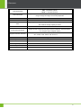
Installation Mode
NO.
1
2
3
4
Description
Use the standard wall-mount bracket that comes with
the device.
Use a 40 to 80 cm ceiling-mount bracket instead of the
The 40 to 80 cm bracket is applicable to the storey
standard bracket that comes with the device.
height of 2.6 to 3.4 m.
Use an 80 to 160 cm ceiling-mount bracket instead of
The 80 to 160 cm bracket is applicable to the storey
the standard bracket that comes with the device.
height of 3.4 to 4.2 m.
Use a 140 to 250 cm floor-mount bracket.
Adjust the camera to the best angle
For detail, please see 11 Auto Test.
13
Note
Fix the bracket on the floor, and fix the device on the
bracket.
3 Installation and Network Configuration
3.2 Network Connection
Connect by Ethernet Cable
1. Use Ethernet cables to connect the device to network or directly to computer.
2. Connect the power supply of the device.
3. In the [Start] menu, select [All Programs] > [Accessories] > [Command Prompt], and input the ping command to
the device address (e.g.: type in ping 192.168.1.88). If Request timed out does not pop up, the device is successfully
connected to network.
Notice:
(1) The default IP address is 192.168.1.88 and the default HTTP port is 80. If needed to change IP address or port, refer
to Network Setting in WEB Server User Manual.
(2) If the device is in a network section different from the computer, refer to How to Configure Domain Name in WEB
Server User Manual for the connection during different network sections.
14
BIOCAM Series Products User Manual
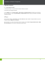
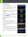
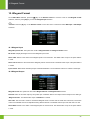
4. Main Menu
There are two types of rights respectively granted to two types of users: the (Ordinary) Users and Administrators.
(Ordinary) Users are only granted the rights of facial verification, while Administrators are granted the access to the
main menu for various operations apart from having all the privileges granted to ordinary users.
Press the [OK] key on the Remote Control to enter the Main Menu interface, shown as bellow:
Any user can access the Main Menu interface by pressing the [OK] button on the Remote Control, if the
system is free from administrators. After administrators are configured on the terminal, the terminal needs
to verify the administrators’ identity before granting them access to the Main Menu. To ensure terminal
security, it is recommended to set an administrator when using the terminal initially. For detailed
operations, see 5.4 Modify User Rights.
The Main Menu includes eight submenus.
Add User: Add users for device.
User Mgt.: Through this submenu, you can browse the user information stored on the terminal, including the User ID,
Face and Role; modify or delete the user information.
Date: Through this submenu, you can set date for device.
Access: Through this submenu, you can set the parameters of the electronic locks and related access devices.
Comm.: Through this submenu, you can check or set related parameters for communication between the terminal and PC,
including the IP address, Gateway, Subnet Mask, Device ID and Comm. Key and so on.
Wiegand Type: Through this submenu, you can set Wiegand Input and Output ★ format for device.
Auto Test: The device automatically tests the image collection effect of a camera. It tests whether a camera can capture
face images properly by displaying a face image in both color and black/white modes.
System: Face Settings, including the 1:1 Threshold, 1: N Threshold, Exposure and Env Mode. Adjust the cameras of
the device to the optimum collection status; Keyboard Definitions; View the system information, including the device
capacity and device information.
15
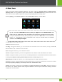
5 Add User
5. Add User
Press the [OK] key on the Remote Control to enter the Main Menu. Press
the [OK] key again to enter the Add User interface, shown as Figure 1:
Face: Enroll a user’s face.
User ID: Enter a user ID. 1- to 5-digit user IDs are supported by default.
ID card: Enroll a user card.
Role: Set the rights of a user. A user is set to (Ordinary) User by default and
can also be set to Administrator. (Ordinary) Users are only granted the
rights of facial verification, while Administrators are granted the access to
the main menu for various operations apart from having all the privileges
granted to (Ordinary) Users.
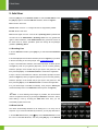
5.1 Enrolling Face
1. On the Add User interface, press [OK] key to enter the Face enrollment
interface.
2. On the displayed face enrollment interface (shown as Figure 2). Eyes show
in the box according to the voice prompts. See 1.2 Enrollment Pose.
3. Upon a successful face collection, the interface prompts "F8 Next" (shown
as Figure 3). Take off your glasses (skip this if you do not wear glasses),
follow the prompts, move forward and put your eyes in the green box. And
then press the [F8] key on the Remote Control to continue the registration.
4. Upon a second successful face collection, the interface prompts "F8 Next"
(shown as Figure 4). Wear your glasses (skip this if you do not wear glasses),
follow the prompts, move forward and put your eyes in the green box. And
then press the [F8] key on the Remote Control to continue the registration.
5. If your facial image is enrolled successfully, voice prompts "Thank you"
and automatically return to the Add User interface (shown as Figure 5).
Note: To avoid deleting facial images by mistake, this device allows
users to re-register a face only by choosing the Edit User menu item. That is,
when adding a user by choosing the Add User menu item, you can
successfully register a face once.
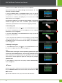
5.2 Enter User ID
The device automatically allocates an ID starting from 1 for every user in
sequence. If you use the ID allocated by the device, you may skip this section.
1. On the Add User interface, press [] key on the Remote Control to move
the cursor on the User ID button, and then press [OK] key on the Remote
16
BIOCAM Series Products User Manual
Control to access the Enter user ID interface, shown as Figure 6:
Tip: The user ID can be modified during initial enrollment, but once
enrolled, it cannot be modified.
2. Press the Numeric Keys on the Remote Control to enter user ID and
press [OK] key to confirm. If a prompt message "User ID exist!" is displayed,
enter another ID. In addition, press [ESC] key to cancel and return to Add
User interface, shown as Figure 7.
Tip: The device supports 1- to 5-digit user IDs by default. If you need to
extend the length of current user ID numbers, please consult our
commercial representatives or for-sale technical support personnel.
5.3 Enrolling Card
1. On the Add User interface, press [] key on the Remote Control to move
the cursor on the Card button, and then press [OK] key to access the Enroll
Card interface, shown as Figure 8:
2. It prompts "Punch Card!" on the Enroll Card interface. Swipe your ID card
properly on the Card Reader.
3. If the card passes the verification, the device displays a prompt message
"Read Successfully! Card No.: **********", shown as Figure 9, and returns to
the Add User interface. The ID card number will display on the Card button,
shown as Figure 10.
5.4 Modify User Rights
1. On the Add User interface, press [] key on the Remote Control to move
the cursor on the Role: User button, shown as Figure 11.
Note: There are two types of roles respectively granted to two types
of users: the User and Administrator. Users are only granted the roles of
facial verification, while Administrators are granted the access to the
main menu for various operations apart from having all the privileges
granted to User.
2. Press [OK] key to change User roles (Change as User or Administrator),
shown as Figure 12:
Notice:
(1) After enter User ID, enroll Face, enroll ID Card and set role, press [ESC]
key on the Remote Control to save user information, and then return to Main
Menu interface.
(2) You must enroll Face or Card, or you can’t save user information.
17
6 User Management
6. User Management
Browse the user information, including the user ID, ID card, FC (face), role.
Edit or delete the basic information of users.
On the Main Menu interface, press the [] key on the Remote Control to
move the cursor on the User Mgt. submenu, and then press [OK] key to
enter the User Management interface, shown as Figure 1.
Note: In User List Area, users are listed in alphabetical order by User
ID. Press [] or [] key to select user, and then press [OK] key to access
the editing interface of this user, edit or delete user information.
6.1 Edit User
On the User Management interface, press [] or [] key to move the
cursor and select user or query user by User ID. (The operation of Query
User, please see 6.3 Query User) And then press [OK] key to enter the
Edit User interface, shown as Figure 2:
The User ID cannot be modified, and the other operations are similar to
those performed to Add User. You can re-enroll your Face, change ID
card number and modify the Role.
6.2 Delete User
On the Edit User interface, you can delete user information.
1. On the Edit User interface, press the [] key on the Remote Control to
move the cursor on the [Delete] key, as shown as Figure 3:
2. Press the [OK] key on the Remote Control, then the confirm box will
pop-up, shown as Figure 4. Press [OK] key to confirm and delete current
user or press [ESC] key to cancel.
6.3 Query User
To facilitate administrators to locate a user quickly from a large number of
enrolled users, the device enables user query by his/her "User ID".
1. On the User Management interface, press any key on the Remote
Control to access the Enter User ID interface, shown as Figure 5:
2. Press the numeric key on the Remote Control to enter ID and press
[OK] key to locate the cursor to the desired user, shown as Figure 6.
18
BIOCAM Series Products User Manual
7 Date/Time Setting
Set Date/Time for device.
On the Main Menu interface, press the [] key on the Remote Control to
move the cursor on the Date/Time submenu, and then press [OK] key to
enter the Date/Time Setting interface, shown as Figure 1:
1. Press [] or [] key to select setting item, Press [] to go forward or
[] to go backward, and set the date and time.
Or press [OK] key to enter the Date/Time input interface, shown as
Figure 2:
Press the numeric keys on the Remote Control to enter Date/Time and
press [OK] key to save, and then return to the Date/Time Setting
interface.
2. After setting, press [] key to move the cursor on the [Save] button and
press [OK] key to save, and then return to the Main Menu interface. Or
press [ESC] key to cancel operation and return to the Main Menu
interface.
Note: After the date and time of the device are changed, the setting will be synchronized to the IPC. If the date and
time are not synchronized in time, you can log in to the device using a browser and then manually synchronize the time.
For detail, please see Appendix 4 How to Sync time for IPC device.
19
8 Access Control Setting
8 Access Control Setting
Through the Access menu, you can set the parameters of the electronic locks and related access control devices.
On the Main Menu interface, press the [] key on the Remote Control to move the cursor on the Access submenu, and
then press [OK] key to enter the Access (Setting) interface:
Lock Delay [s]: The device controls the time to open electronic lock. (Functioning value for 1~10s)
Door Sensor: Some segment time which begin after open door just begin alarm; (The functioning value is 1~99s)
Door Sensor Mode: There are three option that is none (NONE), normal open (NO), normal close (NC). (Press [] key
to select Door Sensor Mode.)The None means the door Sensor doesn’t apply, NO is defined that Thee door can be set
to a Passage Mode in the normal condition, NC means that the door is closed in normal work conditions.
Alarm Delay [s]: Detection to the abnormal door sensor state, the door sensor will generate an alarm signal after a period
of time; this time is door sensor alarm delay. (The functioning value is 1~99s)
20
BIOCAM Series Products User Manual
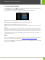
9. Communication Settings
On the Main Menu interface, press the [] key on the Remote Control to move the cursor on the Comm. submenu, and
then press [OK] key to enter the Communication Setting interface:
When the terminal communicates with the PC over Ethernet, you need to check the following settings:
IP Address: Displays the current IP address. The IP address is 192.168.1.88 by default.
Subnet: Displays the current Subnet Mask. The subnet mask is 255.255.255.0 by default.
Gateway: Displays the current Gateway. The gateway is 0.0.0.0 by default.
Device ID: This parameter is used to set the ID of device from 1 to 254. The default value is 1, you can modify as
required.
Comm. Key: To enhance the security of attendance data, you can set a password for the connection between the
terminal and PC. Once the password is set, you can connect the PC with the terminal to access the attendance data only
after entering the correct password. The default password is 0 (that is, no password). Once a password is set, you need to
enter this password before connecting the PC software with the terminal; otherwise, the connection is unsuccessful. 1- to
6-digit passwords are supported.
Note:
(1) On the precondition that the device is connected to the network, you can use a browser to log in to the device and
modify the IP address of the device. For detail, please see Appendix 3 How to change IP Address for device.
(2) After setting, press the [] key on the Remote Control to move the cursor on the [Save] button, and then press [OK]
key to save Communication Settings.
21
10 Wiegand Format
10. Wiegand Format
On the Main Menu interface, press the [] key on the Remote Control to move the cursor on the Wiegand Format
submenu, and then press [OK] key to enter the Wiegand Input interface:
Note: Press the [] key on the Remote Control to move the cursor to switch and select WG Input or WG Output
sub-menu.
10.1 Wiegand Input
Wiegand Input Format: The system has a built-in Wiegand 26-bits and Wiegand 34-bits format.
Bit Counts: Display the length of the current Wiegand input format.
Pulse width: Refers to the width of the Wiegand pulse in microseconds. The default value scope of the pulse width is
1~1000.
Pulse interval: Refers to the interval of the Wiegand pulse in microseconds. The default value scope of the pulse width is
1~10000.
Input content: Refers to the contents input upon successful verification. You can select the "User ID" or "Card No." as the input.
10.2 Wiegand Output
Wiegand Format: The system has two built-in Wiegand 26-bits and Wiegand 34-bits formats.
Failed ID: refers to the value output by the system upon verification failure. The output format is subject to the setting of
"Wiegand Format". The default value scope of Failed ID is 0~65535.
Site Code: The site code is used for customized Wiegand format. The site code is similar to the device ID, but the site
code is customizable and can be duplicated among different devices. The default value scope of the site code is 0~255.
Pulse Width: Refers to the width of the Wiegand pulse in microseconds. The default value scope of the pulse width is
1~1000.
22
BIOCAM Series Products User Manual
Pulse Interval: Refers to the interval of the Wiegand pulse in microseconds. The default value scope of the pulse width is
1~10000.
Output: Refers to the contents output upon successful verification. You can select the "User ID" or "Card Number" as the
output.
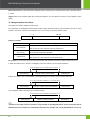
10.3 Wiegand 26-bits Description
The system has a built-in Wiegand 26-bits format.
The composition of the Wiegand 26-bits format contains 2 parity bits and 24 bits for output contents ("User ID" or "Card
Number"). The binary code of 24-bits represent up to 16,777,216 (0~16,777,215) different values.
1
Even parity bit
2
25
26
User ID/Card Number
Odd parity bit
Definition of Fields:
Field
Even parity bit
User ID/Card Number
(bit 2-bit 25)
Odd parity bit
Meaning
Judged from bit 2 to bit 13. The even parity bit is 1 if the character has an
even number of 1 bits; otherwise, the even parity bit is 0.
User ID/Card Number (Card Code, 0~16777215)
Bit 2 is the Most Significant Bit (MSB).
Judged from bit 14 to bit 25. The odd parity bit is 1 if the character has an
even number of 1 bits; otherwise, the odd parity bit is 0.
For example, for a user with user ID of 12345, the enrolled card number is 0013378512 and the failed ID is set to 1.
1. When the output is set to "User ID", the Wiegand output is as follows upon successful verification:
00000000000110000001110011
Even parity bit
User ID = Binary code of 12345
Odd parity bit
2. When the output is set to "Card Number", the Wiegand output is as follows upon successful verification:
11100110000100011110100000
Even parity bit
Card No. = Binary code of 0013378512
Odd parity bit
3. The Wiegand output is as follows upon verification failure:
00000000000000000000000010
Even parity bit
Failed ID = Binary code of 1
Odd parity bit
Note: If the output contents exceed the scope allowed for the Wiegand format, the last several bits will be
adopted and first several bits are automatically discarded. For example, the user ID 888 888 888 is 110 100 111
23
10 Wiegand Format
110 110 101 111 000 111 000 in binary format. Wiegand26 only supports 24 bits, that is, it only outputs the last 24
bits, and first 6 bits "110 100" are automatically discarded.
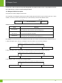
10.4 Wiegand 34-bits Description
The system has a built-in Wiegand 34-bits format.
The composition of the Wiegand 34-bits format contains 2 parity bits and 32 bits for output contents ("User ID" or "Card
Number"). The binary code of 32-bits represent up to 4 294 967 296 (0-4 294 967 295) different values.
1
Even parity bit
2
33
User ID/Card Number
34
Odd parity bit
Definition of Fields:
Field
Meaning
Judged from bit 2 to bit 17. The even parity bit is 1 if the character has an
Even parity bit
even number of 1 bits; otherwise, the even parity bit is 0.
User ID/Card Number
(bit 2-bit 25)
User ID/Card Number (Card Code, 0~4 294 967 295)
Bit 2 is the Most Significant Bit (MSB).
Judged from bit 18 to bit 33. The odd parity bit is 1 if the character has an
Odd parity bit
even number of 1 bits; otherwise, the odd parity bit is 0.
For example, for a user with user ID of 123456789, the enrolled card number is 0013378512 and the failed ID is set to 1.
1. When the output is set to "User ID", the Wiegand output is as follows upon successful verification:
0000001110101101111001101000101011
Even parity bit
User ID = Binary code of 12345
Odd parity bit
2. When the output is set to "Card Number", the Wiegand output is as follows upon successful verification:
0000000001100110000100011110100001
Even parity bit
Card No. = Binary code of 0013378512
Odd parity bit
3. The Wiegand output is as follows upon verification failure:
0000000000000000000000000000000010
Even parity bit
Failed ID = Binary code of 1
Odd parity bit
24
BIOCAM Series Products User Manual
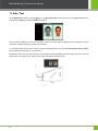
11 Auto Test
On the Main Menu interface, press the [] key on the Remote Control to move the cursor on the Auto Test submenu,
and then press [OK] key to enter the Auto Test interface:
After successful installation of the device, adjust the camera to the best angle to implement face recognition and video
surveillance. Detailed adjustment methods are as follows:
1. The angle adjuster stands with an about 3 meters' horizontal distance from the Face Recognition Camera. (Note:
That the adjuster must be about 1.7 meters high.).
2. Rotate the device up, down, left, and right to ensure that the facial image display inside the green box on the Auto Test
page (shown as the figure on the right); that is to adjust the camera to the best angle.
25
12 System Settings
12 System Settings
On the Main Menu interface, press the [] key on the Remote Control to move the cursor on the System submenu, and
then press [OK] key to enter the (System) Settings interface:
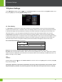
12.1 Face Setting
1: 1 Threshold: This parameter is used to set the threshold of matching between current face and the facial template
enrolled in the terminal in the 1:1 verification mode. If the similarity between current face and the facial template enrolled
in the terminal is larger than this threshold, the matching is successful; otherwise, the matching is not successful. The
valid value scope is 70~120. The higher the threshold, the lower the FAR and the higher the FRR, and vice versa.
1:N Threshold: This parameter is used to set the threshold of matching between current face and the facial template
enrolled in the terminal in the 1: N verification mode. If the similarity between current face and the facial template enrolled
in the terminal is larger than this threshold, the matching is successful; otherwise, the matching is not successful. The
valid value scope is 80-120. The higher the threshold, the lower the FAR and the higher the FRR, and vice versa.
The recommended thresholds are as follows:
FRR
High
Medium
Low
FAR
Threshold
1: N
1:1
85
80
Medium
82
75
High
80
70
Low
Exposure: This parameter is used to set the exposure value of the camera. The default value is 300.
Env Mode: Set the device's light sensitivity. When faces are unrecognizable due to poor video quality at the locations
where the device is installed, the device switches to the black-and-white mode automatically. Available options are Low,
Medium, and High. (Low by default)
Note:
(1) After setting, press the [] key on the Remote Control to move the cursor on the [Save] button, and then press [OK]
key to save the settings.
(2) Improper adjustment of the Exposure parameters may severely affect the performance of the terminal. Please
adjust the Exposure parameter only under the guidance of the after-sales service personnel from our company.
26
BIOCAM Series Products User Manual
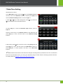
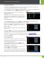
12.2 Keyboard Definitions
You can define six keys ([F1] ~ [F6]) as attendance status shortcut keys. On the main interface of the terminal, press
corresponding keys ([F1] ~ [F6]) and the attendance status will be displayed.
1. On the Main Menu interface, press the [] key on the Remote Control to move the cursor on the Keyboard submenu,
and then press [OK] key to enter the Keyboard (Settings) interface, shown as Figure 1.
2. All the defined shortcut keys and their functions are listed on the
Keyboard (Settings) interface:
(Shortcut) Key: Can select as [F1] ~ [F6]. The status shortcut keys
include: Chk-In (Check-In), Chk-Out (Check-Out), Brk-Out (Break-Out),
Brk-In (Break-In), OT-In (Overtime Check-In), and OT-Out (Overtime
Check-Out).
12.2.1 Edit Shortcut Keys
1. On the Keyboard (Settings) interface, press the [] key on the Remote Control to move the cursor and select
shortcut key, and then press [OK] key to enter the Edit interface, shown as Figure 2.
Function: Press the [] key on the Remote Control to move the cursor
and select this item, and then press [OK] key to switch and select as
Status or Undefine.
Code: Non-modifiable. It is changed accordingly with the selected label of
the shortcut key.
Label: Press the [] key to move the cursor and select this item, and then
press [OK] key to switch and select attendance status (Check In, Check Out, Break Out, Break In, OT-In, or OT-Out.).
Auto Switch: Set the auto switch time for attendance status, for detail; please see 12.2.2 Auto Switch Setting.
2. After setting, press [] key to move the cursor on the [Save] button, and then press [OK] key to save and return to the
Keyboard (Settings) interface.
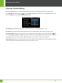
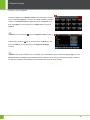
12.2.2 Auto Switch Setting
When a selection is the status key, enable the Auto Switch function (i.e.
the timing state transition function), the terminal automatically switches the
attendance status at the specified time.
1. On the Keyboard (Settings) interface, press the [] key on the
Remote Control to move the cursor and select shortcut key, and then
press [OK] key to enter the Edit interface.
2. Press the [] key on the Remote Control to move the cursor and
select Auto Switch item, shown as Figure 3:
3. Press the [OK] key on the Remote Control to enable (ON) the Auto
Switch function, and then pop-up the auto switch time setting bar (from left
to right: Sunday, Monday, Tuesday, Wednesday, Thursday, Friday, and
27
12 System Settings
Saturday.); shown as Figure 4.
4. Press the [] key on the Remote Control to move the cursor and select
day, and then press [OK] key to enter the Time Setting interface; press the
numeric on the Remote Control to input time (shown as Figure 5), and
then press [OK] key to save and return to the Edit interface, shown as
Figure 6.
Note: You can press the [
] key on the Remote Control to input ":".
5. After setting, press the [] key to move the cursor on [Save] key, and
then press [OK] key to save and return to the Keyboard (Settings)
interface.
Note: After the Auto Switch function is enabled, on the initial interface users can press the [F1] to [F6] keys on the
Remote Control to manually modify attendance statuses; and after 60 seconds, the terminal automatically switches to
the attendance statuses corresponding to the current time set in the Auto Switch function.
28
BIOCAM Series Products User Manual
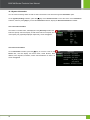
12.3 System Information
You can check the storage status as well as version information of the device through the Information option.
On the (System) Settings interface, press the [] key on the Remote Control to move the cursor on the Information
submenu, and then press [OK] key to enter the Information interface, display the Records Information in default:
12.3.1 Records Information
The number of enrolled users, will displayed on the [Records] interface; the
total face capacity and used capacity as well as the total record capacity and
used capacity are graphically displayed respectively, shown as Figure 1.
12.3.2 Device Information
On the Information Interface, press the [] key to move the cursor on the
Device item, and then display the Device Name, Serial Number, MAC
Address, Face Algorithm, Firmware, Vendor and Manufacturer of device. As
shown as Figure 2.
29
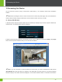
13 Accessing the Device
13 Accessing the Device
You can access the camera by using a web browser, mobile device, or our company's network video surveillance
software.
Note: Before accessing the device, connect the camera to the network and power supply. Then, check whether the
network interface indicator displays normal status to ensure that the network connection is normal.
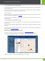
13.1 Using a Web Browser
1. Start the browser. Enter the dynamic domain name or IP address (for example, http://192.168.1.88) in the address bar,
and press Enter. The following login interface is displayed.
2. Enter the User name and Password. (In initial state, the User name is admin and Password is 123456.) Click [Login]
button to enter the preview interface where you can start video surveillance.
Note: If you use a browser to access the device for the first time, you need to download and install ActiveX
(ActiveXPlugin.ocx). Enter the device's IP address in the Address Bar and press Enter key, the ActiveX download
window will popup. Then follow instructions displayed on the ActiveX download window to download and install the
30
BIOCAM Series Products User Manual
ActiveX. For details about how to use a browser for video surveillance, see the Web Server User Manual, which is
available on the disk delivered with the device.
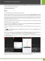
13.2 Using a Mobile Device
Note:
(1) For the UID of a device, see the label on the back of the device.
(2) After successful connecting the device to the network, you can add the device in the ZKiVision (Mobile surveillance)
software in UID mode. After the device is added successfully, you can receive and browse surveillance videos on their
mobile phones in real time by connecting their mobile phones to the front-end surveillance devices via a mobile wireless
network. (Tips: In an LAN, you can use any set of digits or letters to replace a UID; however, in a WAN, you must enter a
correct UID provided by your service provider.)
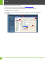
The following takes adding a device via an IP address as an example to illustrate how to access a device by using the
ZKiVision (mobile phone) monitoring software:
1. Download and install the ZKiVision (mobile phone) monitoring software ZKiVision Pro 2.0.apk or ZKiVision Pro
2.0.ipa from Google Play or Apple Store on your mobile phone.
2. Click the icon ZKiVision on the mobile device to start the video player. Figure 1 shows the initial interface of the
software.
3. Click
. The Select Add way dialog box (see Figure 2). Select an option in the dialog box. The Add Device screen
will display (see Figure 3).
4. Specify device login information, including Name (device name), Address (IP address of the device), Port (P2P port of
the device, which is port 19888 by default), User (admin by default), and Password (123456 by default).
5. Click [Sure] button to save the configuration and return to the View Video screen, which displays the added device and
its channels (see Figure 4).
6. Select a device by clicking the device icon on the View Video screen (the selected device is highlighted in blue; see
Figure 5). The software checks and shows the number of channels of the device automatically.
31
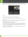
13 Accessing the Device
7. Select a channel number (see Figure 5), which is then highlighted in blue. The View Video screen shows the
surveillance video of the channel in real time (see Figure 6). To close the video, click the corresponding channel number
(in blue)
Note:
(1) The operating system of the mobile device must be Android, iOS, or BlackBerry.
(2) Viewing videos will use data. For details about charges, consult your network service provider.
(3) Open the mobile phone monitoring software, and add a P2P-capable device by using a UID for remote view and
monitoring.
(4) Add a device by scanning a QR code, searching in an LAN, or manually entering a UID; see the ZKiVision User
Manual (Mobile Phone), which is available on the disk delivered with the camera.
13.3 Using the Network Video Surveillance Software
The disk delivered with the camera contains the network video surveillance software ZKiVision Client Software provided
by our company free of charge. You can use this software to manage and monitor in real time multiple devices at the
same time. You can install the ZKiVision Client Software, start the ZKiVision Client Software, add the devices to the
system, and then start real-time video surveillance.
For details about how to use the ZKiVision Client Software, see the ZKiVision Client Software User Manual, which is
available on the disk delivered with the camera.
32
BIOCAM Series Products User Manual
33
Appendix
Appendix
Appendix 1 Introduction to Wiegand
Wiegand26 is an access control standard protocol established by the Access Control Standard Subcommittee affiliated to
the Security Industry Association (SIA). It is a non-contact IC card reader interface and output protocol.
Wiegand26 defines the interface between the card reader and controller used in the access control, security and other
related industrial fields. Wiegand26 helps standardize the work of the card reader designers and controller manufacturers.
The access control products manufactured by our company are also designed by following designed following.
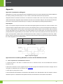
Digital Signals
Figure 1 is a sequence diagram in which the card reader sends digital signals in bit format to the access controller. In this
sequence diagram, Wiegand follows the SIA’s access control standard protocol for the 26-bit Wiegand card reader (one
pulse time ranges between 20us and 100us, and the pulse jump time ranges between 200us and 20ms). Data1 and Data0
are high level (larger than Voh) signals till the card reader prepares to send a data stream. The asynchronous low-level
pulse (smaller than Vol) generated by the card reader is sent to the access control panel (The saw-tooth wave shown as
Figure 1) through Data1 or Data0. Data1 and Data0 pulses will neither overlap nor be generated synchronously. Table 1
lists the maximum and minimum pulse width (a consecutive pulse) and pulse jump time (time between pulses) allowed by
the F series fingerprint access control terminal.
Symbol
Definition
Typical Value of Reader
Tpw
Pulse Width
100 µs
Tpi
Pulse Interval
1 ms
Table 1 Pulse Time
Figure 1 Sequence Diagram
Appendix 2 How to achieving Attendance, Access and IPC ZKiVision function
How to implement the staff attendance function?
1. Install and power on the device. For details about how to install the device, see the BIOCAM Series Products
Installation Guide.
2. Add users to the device. That is, register the faces and cards of people whose attendance should be managed, and set
user rights. For details about how to add users, see 5. Add User.
3. Users sign in by using faces or cards.
4. Use the ZKiVision Client Software to download and take statistics on the staff attendance data, and analyze or view the
attendance reports. For details about the operation methods, see the ZKiVision Client Software User Manual.
34
BIOCAM Series Products User Manual
How to implement the access control function?
1. Install the device without powering on the device. For details about how to install the device, see the BIOCAM Series
Products Installation Guide.
2. Install door locks and connect the door locks to the device by using the related connection cables. For details about
how to install door locks, see the installation manual of the door locks.
3. Power on the device.
4. Add users to the device. That is, register the faces and cards of people for whom the doors can be opened, and set user
rights. For details about how to add users, see 5. Add User.
5. Users open doors by using faces or cards. The device opens doors or generates alarms based on the user
authentication results.
How to implement the video ZKiVision function?
1. Install and power on the device. For details about how to install the device, see the BIOCAM Series Products
Installation Guide.
2. Use the Search tool configured for the BIOCAM Series to search the device and modify the IP address and port number
of the device.
3. Use a web browser, mobile devices, or network video surveillance software to access the device. For details about the
operation method, see 13 Accessing the Device.
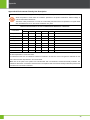
Appendix 3 How to change IP Address for device
1. Access the camera by using a web browser. For detail, please see 13.1 Using a Web Browser.
2. Click [System Config] > [Net Setting] to enter the Net Setting interface, as shown as the following figure:
3. Modify the IP Address as needed, and then press [Save] button to save settings.
35
Appendix
Appendix 4 How to Sync time for IPC device
1. Access the camera by using a web browser. For detail, please see 13.1 Using a Web Browser.
2. Click [System Config] > [System Setting] > [Common Setting] to enter the Common Setting window.
3. Click [SyncPC] button to synchronization time.
4. Click [Save] button to save, the system will pop-up the Save successful prompt box, and then click the [OK] button to
close the prompt box.
36
BIOCAM Series Products User Manual
Appendix 5 Statement on Human Rights and Privacy
Dear Customers:
Thank you for choosing the hybrid biometric products designed and manufactured by us. As a world-renowned provider of
biometric technologies and services, we pay much attention to the compliance with the laws related to human rights and
privacy in every country while constantly performing research and development.
We hereby make the following statements:
1.
All of our multi-bio recognition devices for civil use only collect the characteristic points of multi-bio instead of the
multi-bio images, and therefore no privacy issues are involved.
2.
The characteristic points of multi-bio collected by our products cannot be used to restore the original multi-bio images,
and therefore no privacy issues are involved.
3.
We, as the equipment provider, shall not be held legally accountable, directly or indirectly, for any consequences
arising due to the use of our products.
4.
For any dispute involving the human rights or privacy when using our products, please contact your employer directly.
Our multi-bio products for police use or development tools support the collection of the original multi-bio images. As for
whether such a type of multi-bio collection constitutes an infringement of your privacy, please contact the government or
the final equipment provider. We, as the original equipment manufacturer, shall not be held legally accountable for any
infringement arising thereof.
The law of the People’s Republic of China has the following regulations regarding the personal freedom:
1.
Unlawful arrest, detention or search of citizens of the People's Republic of China is prohibited; infringement of
individual privacy is prohibited.
2.
The personal dignity of citizens of the People's Republic of China is inviolable.
3.
The home of citizens of the People's Republic of China is inviolable.
4.
The freedom and privacy of correspondence of citizens of the People's Republic of China are protected by law.
At last we stress once again that biometrics, as an advanced recognition technology, will be applied in a lot of sectors
including e-commerce, banking, insurance and legal affairs. Every year people around the globe suffer from great loss
due to the insecurity of passwords. The biometric products actually provide adequate protection for your identity under a
high security environment.
37
Appendix
Appendix 6 Environment-Friendly Use Description
The Environment Friendly Use Period (EFUP) marked on this product refers to the safety period of time in
which the product is used under the conditions specified in the product instructions without leakage of
noxious and harmful substances.
The EFUP of this product does not cover the consumable parts that need to be replaced on a regular basis
such as batteries and so on. The EFUP of batteries is 5 years.
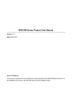
Names and Concentration of Toxic and Hazardous Substances or Elements
Toxic and Hazardous Substances or Elements
Parts Name
Pb
Hg
Cd
Cr6+
PBB
PBDE
Chip resistor
×
○
○
○
○
○
Chip capacitor
×
○
○
○
○
○
Chip inductor
×
○
○
○
○
○
Chip diode
×
○
○
○
○
○
ESD components
×
○
○
○
○
○
Buzzer
×
○
○
○
○
○
Adapter
×
○
○
○
○
○
Screws
○
○
○
×
○
○
○: Indicates that this toxic or hazardous substance contained in all of the homogeneous materials for this part is below
the limit requirement in SJ/T11363-2006.
×: Indicates that this toxic or hazardous substance contained in at least one of the homogeneous materials for this
part is above the limit requirement in SJ/T11363-2006.
Note: 80% of the parts in this product are manufactured with non-hazardous environment-friendly materials. The
hazardous substances or elements contained cannot be replaced with environment-friendly materials at present due
to technical or economical constraints.
38
BIOCAM Series Products User Manual
39