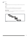
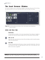
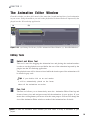
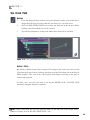
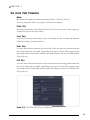
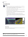
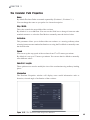
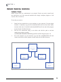
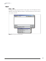
1
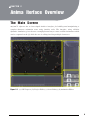
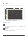
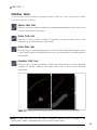
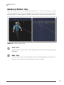
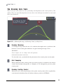
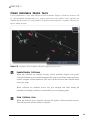
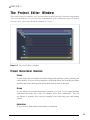
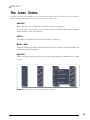
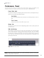
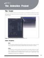
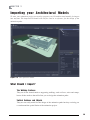
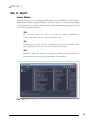
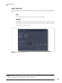
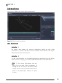
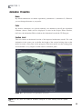
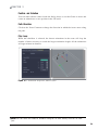
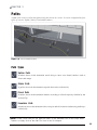
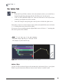
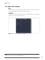
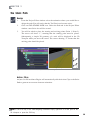
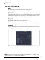
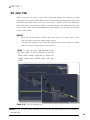
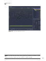
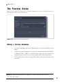
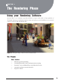
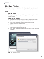
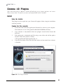
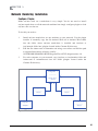
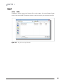
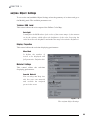
March 2011 User Manual Learn More & Purchase For more information and a complete list of features and enhancements in an(i)ma®, visit www.anima.com. To purchase aXYZ design products, go to www.anima.com online shop To locate an aXYZ design Authorized Reseller nearest you, visit www.axyz-design.com > Resellers. Email: [email protected] Copyright (c) aXYZ design® 2011 Contents CHAPTER 1 Introduction What is an(i)ma? . . . . . . . . . . . . . . . . . . . . . . . . . . . . . . . . . . . . . . . . . . 6 Features . . . . . . . . . . . . . . . . . . . . . . . . . . . . . . . . . . . . . . . . . . . . . . . . . 7 System Requirements . . . . . . . . . . . . . . . . . . . . . . . . . . . . . . . . . . . . . . 7 CHAPTER 2 Anima Iterface Overview The Main Screen . . . . . . . . . . . . . . . . . . . . . . . . . . . . . . . . . . . . . . . . . . 8 The 3D Viewport . . . . . . . . . . . . . . . . . . . . . . . . . . . . . . . . . . . . . . . . . . 9 Transformation Tools . . . . . . . . . . . . . . . . . . . . . . . . . 9 Creation Tools . . . . . . . . . . . . . . . . . . . . . . . . . . . . . 10 Navigation Tools . . . . . . . . . . . . . . . . . . . . . . . . . . . .11 Rendering Method Tool . . . . . . . . . . . . . . . . . . . . . . 12 The Drawing Aids Tools . . . . . . . . . . . . . . . . . . . . . . 13 Crowd Avoidance Engine Tools . . . . . . . . . . . . . . . . 14 The Project Editor Window . . . . . . . . . . . . . . . . . . . . . . . . . . . . . . . . . 15 Project Hierarchical Structure . . . . . . . . . . . . . . . . . 15 The Asset Browser Window . . . . . . . . . . . . . . . . . . . . . . . . . . . . . . . . . 17 Actors and Clips Tabs . . . . . . . . . . . . . . . . . . . . . . . . 17 Modifiers Tab . . . . . . . . . . . . . . . . . . . . . . . . . . . . . . 18 Properties Tab . . . . . . . . . . . . . . . . . . . . . . . . . . . . . . 18 The Animation Editor Window . . . . . . . . . . . . . . . . . . . . . . . . . . . . . . . 19 Editing Tools . . . . . . . . . . . . . . . . . . . . . . . . . . . . . . . 19 The Icon States . . . . . . . . . . . . . . . . . . . . . . . . . . . . . . . . . . . . . . . . . . . 20 Preferences Panel . . . . . . . . . . . . . . . . . . . . . . . . . . . . . . . . . . . . . . . . . 21 CHAPTER 3 The Animation Project The Scene . . . . . . . . . . . . . . . . . . . . . . . . . . . . . . . . . . . . . . . . . . . . . . . 22 Scene Properties . . . . . . . . . . . . . . . . . . . . . . . . . . . . 22 Render Quality . . . . . . . . . . . . . . . . . . . . . . . . . . . . . 24 Material Presets . . . . . . . . . . . . . . . . . . . . . . . . . . . . 25 Information . . . . . . . . . . . . . . . . . . . . . . . . . . . . . . . . 25 Material Preset File Configuration . . . . . . . . . . . . . 26 Contents Importing your Architectural Models . . . . . . . . . . . . . . . . . . . . . . . . . . 28 What should I import? . . . . . . . . . . . . . . . . . . . . . . . 28 How to import? . . . . . . . . . . . . . . . . . . . . . . . . . . . . 29 Groups . . . . . . . . . . . . . . . . . . . . . . . . . . . . . . . . . . . . . . . . . . . . . . . . . 31 Examples of Management . . . . . . . . . . . . . . . . . . . . 31 Group Properties . . . . . . . . . . . . . . . . . . . . . . . . . . . 31 Animations . . . . . . . . . . . . . . . . . . . . . . . . . . . . . . . . . . . . . . . . . . . . . . 32 Add Animation . . . . . . . . . . . . . . . . . . . . . . . . . . . . . 32 Animation Properties . . . . . . . . . . . . . . . . . . . . . . . . 33 Paths . . . . . . . . . . . . . . . . . . . . . . . . . . . . . . . . . . . . . . . . . . . . . . . . . . . 35 Path Types . . . . . . . . . . . . . . . . . . . . . . . . . . . . . . . . . 35 The Spline Path . . . . . . . . . . . . . . . . . . . . . . . . . . . . . 36 The Spline Path Properties . . . . . . . . . . . . . . . . . . . . 37 The Stairs Path . . . . . . . . . . . . . . . . . . . . . . . . . . . . . 38 The Stairs Path Properties . . . . . . . . . . . . . . . . . . . . 39 The Fixed Path . . . . . . . . . . . . . . . . . . . . . . . . . . . . . 40 The Fixed Path Properties . . . . . . . . . . . . . . . . . . . . 41 The Escalator Path . . . . . . . . . . . . . . . . . . . . . . . . . . 42 The Escalator Path Properties . . . . . . . . . . . . . . . . . 43 Actors . . . . . . . . . . . . . . . . . . . . . . . . . . . . . . . . . . . . . . . . . . . . . . . . . . 44 Installing Actors . . . . . . . . . . . . . . . . . . . . . . . . . . . . 44 Adding an Actor to the scene . . . . . . . . . . . . . . . . . . 45 The Actor Properties . . . . . . . . . . . . . . . . . . . . . . . . 46 The Actor Path . . . . . . . . . . . . . . . . . . . . . . . . . . . . . 48 Modifiers . . . . . . . . . . . . . . . . . . . . . . . . . . . . . . . . . . . . . . . . . . . . . . . 49 Adding a Modifier . . . . . . . . . . . . . . . . . . . . . . . . . . 49 The Modifier Properties . . . . . . . . . . . . . . . . . . . . . . 50 The Preview Dialog . . . . . . . . . . . . . . . . . . . . . . . . . . . . . . . . . . . . . . . 53 Making a Preview Animation . . . . . . . . . . . . . . . . . . 53 Contents CHAPTER 4 The Rendering Phase Using your Rendering Software . . . . . . . . . . . . . . . . . . . . . . . . . . . . . . 54 The Plugins . . . . . . . . . . . . . . . . . . . . . . . . . . . . . . . . . . . . . . . . . . . . . . 54 3ds Max Plugins . . . . . . . . . . . . . . . . . . . . . . . . . . . . . . . . . . . . . . . . . . 55 Install . . . . . . . . . . . . . . . . . . . . . . . . . . . . . . . . . . . . 55 Network Rendering Installation . . . . . . . . . . . . . . . . 56 Import . . . . . . . . . . . . . . . . . . . . . . . . . . . . . . . . . . . . 57 an(i)maMesh Settings. . . . . . . . . . . . . . . . . . . . . . . . . 58 Cinema 4D Plugins . . . . . . . . . . . . . . . . . . . . . . . . . . . . . . . . . . . . . . . . 60 Install . . . . . . . . . . . . . . . . . . . . . . . . . . . . . . . . . . . . 60 Network Rendering Installation . . . . . . . . . . . . . . . . 61 Import . . . . . . . . . . . . . . . . . . . . . . . . . . . . . . . . . . . . 62 an(i)ma Object Settings . . . . . . . . . . . . . . . . . . . . . . 63 CHAPTER 1 Introduction What is an(i)ma? Overview Human characters in 3D scenes become ever more important in visualizations, animations and illustrations. Character animation is a specialized area of the animation process and because of its complexity, most of the animation work has catered to very advanced users and programmers, leaving virtually no access to all other users. an(i)ma® changes all of that! an(i)ma® is the fastest stand-alone character animation application developed especially for architects and designers, ideal for quickly and easily creating stunning 3D animations in less time. Our motion-editing tools and content make 3D character animation easy and affordable and enables creative and technical artists to take on demanding animation-intensive projects. an(i)ma® 3D character-animation software was designed to slash production time on 3D human character animation for architectural visualizations and full-motionvideo, and provide high-quality interactive visualizations within the 3D Viewport and an intuitive toolset for creating real-time simulations. Importing animations into your favorite professional 3D Modeling & Rendering Package is really simple! Creating complex character animation scenes for your architectural productions has never been so easy! 6 CHAPTER 1 Features Highlights WYSIWYG simple and intuitive iterface. Fast and easy Drag&Drop editing system for Actors and Action Clips. AI Collision Brain predicts collisions between agents. Automatic Procedural Motions. Automatic Motion Blending system to achieve super-realistic animations. Ready-To-Run Agent and Action Clip Libraries. Imports .3ds, .obj, and .lwo. geometries. Importing plugins for Autodesk 3DS Max and Maxon Cinema 4D. Cloner modifier to simulate the behavior of a large number of characters. System Requirements System Requirements an(i)ma 1.0 has been designed to run on a wide range of hardware and software configurations, although performance levels will vary depending on the processing speed and available memory of the system. For general animation and rendering Intel® Pentium® 4 1.4 GHz or equivalent AMD® processor (Intel® 64 or AMD64 processor recommended), 2 GB RAM (8 GB recommended), 3 GB Available Hard-Disk Space, Direct3D® 10 technology, Direct3D 9, or OpenGL®-capable graphics card (256 MB or higher video card memory, 1 GB or higher recommended), Internet connection for web downloads and an(i)ma Registering access. Operating Systems Microsoft® Windows® 7 Professional x32 or x64, Microsoft® Windows Vista® Business x32 or x64 (SP2 or higher), Microsoft® Windows® XP Professional x32 or x64 (SP2 or higher). 7 CHAPTER 2 Anima Iterface Overview The Main Screen an(i)ma™ software has a clean simple intuitive interface for building and manipulating a complex character animation scene using intuitive tools. The interface, using collision dynamics simulation, gives the user a straightforward way to create realistic animations which can be computed on the fly while the user is editing involving multiple characters. (a) (b) (c) (d) Figure 2-1. (a) 3D Viewport, (b) Project Editor, (c) Asset Library, (d) Animation Editor. 8 CHAPTER 2 The 3D Viewport This window shows in real-time the result of your animation project. It also enables you to design Paths, move Actors, assign Action Clips and perform all the editing tasks. (c) (d) (e) (b) (a) Figure 2-2. (a) Transformation Tools, (b) Creation Tools, (c) Navigation Tools, (d) Drawing Aids Tools, (e) Collision Brain Tools. Transformation Tools Select and Move Tool With the Select and Move tool you can select from the 3D Viewport any part of an animation such as splines, stairs, escalators and fixed paths, modify their geometry and reposition them on the 3D architectural model. You can also define offsets for each Actor in the scene. Rotate Tool It allows you to freely rotate splines and fixed paths in X, Y planes. During the operation the cursor will change to a rotation icon. 9 CHAPTER 2 Creation Tools Use these tools to create all kinds of animation paths to define the course or direction in which the Actors in a scene will move. Spline Path Tool This tool provides a simple method for creating animation paths to drive Actors over surfaces such as floors and ramps. Stairs Path Tool This tool is used to define a simple 3D geometry in order to make Actors in the animation go up and down stairs realistically. Fixed Path Tool It creates a type of path where trajectories are fixed. This means that the spatial layout of the actions cannot be modified. However you can alter the time in which an Actor will perform. Escalator Path Tool This tool gives you the possibility to define the 3D geometry of a fully animated escalator or moving walkway and make Actors ride or step on and off them realistically. a b c d Figure 2-3. (a) Spline Path, (b) Stairs Path, (c) Fixed Path, (d) Escalator Path. Note To enable these tools you must select an animation either from the 3D Viewport or the Project Editor window. Subsequently, the tool icons will become active. 10 CHAPTER 2 Navigation Tools These tools are used to manipulate your point of view of the model. They include the Pan, Zoom and Orbit tools. Pan Tool Use the Pan tool to move the camera (your view) vertically and horizontally. Activate the Pan tool from either the Navigation Tool palette or using the keyboard shortcut: ALT + right mouse button. Zoom Tool Use the Zoom tool to move the camera (your view) in or out. Activate the Zoom tool from either the Navigation Tool palette or using the keyboard shortcut: ALT + left mouse button + right mouse button. Orbit Tool Use the Orbit tool to rotate the camera about the model. This tool is useful when viewing geometry from the outside. Activate the Orbit tool from either the Navigation Tool palette or using the keyboard shortcut: ALT + left mouse button. Pivot Snapping Tool When the Pivot Snapping tool is activated the selected object acts as the center or pivot for the previous tools. Activate the Pivot Snapping tool from the Navigation Tool palette. Layer List Tool By clicking on this icon the Layer List window will be displayed. When importing a .3ds or .Obj file into an(i)ma the name on the original layers/materials is kept. Use the Layer List tool to control the visibility and color of geometry within large models. 11 CHAPTER 2 Rendering Method Tools These tools are used to set the rendering method for the current 3D Viewport. In large scenes, performance levels can vary depending on the video card processing-speed and memory. Changing from one render method to another can be useful to speed up the drawing process. Figure 2-4. Solid View, BBox View. Solid View This tool renders objects with smooth shading and normal maps, and displays specular highlights. BBox View This tool draws objects as bounding boxes with no shading applied. A bounding box is defined as the smallest box that completely encloses an object. 12 CHAPTER 2 The Drawing Aids Tools These tools give you control over the positioning and alignment of the control points of the splines. They are especially important tools for those who build precise models in real-world units of measurement. (b) (a) (c) Figure 2-5. (a) Warning Message, (b) Warning Cloud, (c) Help Lines. Drawing Warnings A warning message alerts the user of a condition that might cause a problem in the behavior of Actors during the animation. A typical warning message can be: WARNING! Curve angles are too sharp and will generate abnormal movements on Actors. To solve this issue, you should edit the placement of the control points on the spline. Grid Snapping When editing the spline control points, the mouse position is rounded to the nearest virtual lines passing orthogonally or obliquely at 45o through the previous spline control point. Drawing Limiting Control When this tool is ON, the placement of the spline control points will be regulated by some internal calculations that will indicate when a position is OPTIMAL. 13 CHAPTER 2 Crowd Avoidance Engine Tools Crowd simulation is easy with an(i)ma Crowd Avoidance Engine. Character motions will be choreographed automatically for a perfect interaction and realistic result. an(i)ma can simulate the movement of a large number of characters and replicate a complex collective behavior within seconds. Figure 2-6. an(i)ma Crowd Avoidance Engine computing in progress. Enable/Disable Collisions When the collisions are enabled, an(i)ma Crowd Avoidance Engine will predict collisions between Actors and will automatically create an avoidance path to perform a realistic complex collective behavior. The saved .ani file will store the collision details from your scene. When collisions are disabled, Actors will pass through each other during the simulation. Disabling collisions is useful while you are designing paths. View Collision Area When the collision area is enabled, an(i)ma will predict collisions between Actors. The collision areas will be shown as red paths. 14 CHAPTER 2 The Project Editor Window This window shows a schematic view of all the elements hierarchically structured compounding your scene and allows for a fast and easy understanding of the animation project. From here you can create, select and edit all the elements in a scene. Figure 2-7. The Project Editor Window. Project Hierarchical Structure Scene Use the Scene slot to load the base model, change units and Fps, control collisions and render quality. To access Scene parameters, click on the Scene slot in the Project Editor window, then select the Properties tab in the bottom section of the panel. Group It is the highest level in the hierarchical structure of a scene. It can contain multiple animations that make up a unit, for example „First Floor Animations‰. You can use Groups to organize your scene by changing colors and using your own naming criteria. Animation A set of Actors, Paths and Actions defines an animation. 15 CHAPTER 2 Actors It is a 3D human figure who acts in the 3D stage based on Paths and Actions previously defined. Path It is the course or direction in which the Actors in your scene will move. It consists of four types of courses: Spline, Stairs, Fixed and Escalator. Action Cli ps It is a movement or a series of movements performed by an Actor which define their behavior or conduct in the animation. Model Group Animation Actor Path Action Clip Figure 2-8. The Project Hierarchical Structure. ! 16 CHAPTER 2 The Asset Browser Window It is used to manage Actors, Action Clips, Modifiers and Object Properties. The following description provides an overview of the functionality of the Asset Browser window. (a) (b) (c) Figure 2-9. Icon View of the Actors Library ,View as List of the Action Clip Library, Properties Panel. Actors and Cli ps Tabs Collections A drop down box provides a list of the Actors/Action Clip collections installed in an(i)ma. Just select one of them to display the list of Actors/Action Clips available. View as List It provides a list view of the Actors/Action Clips including a small icon and description of the asset characteristics. Icon View It shows each Actor/Action Clip item as a large icon with its label below. Since the icons and the file names are larger than those in the View as List format, this view makes assets more recognizable. Note Before you drag and drop any asset, you must select the destiny object. Example: To add an Action Cli p to a Spline Path in your animation you must select the Spline Path first. 17 CHAPTER 2 Modifiers Tab The modifiers change some portion of the definition of an animation that may result in a change in the appearance or behavior. After drag-dropping a modifier into the Animation slot in the Project Editor window, the Modifier control will appear just below it . Once you have applied modifiers to an animation you can select the Modifier slot in the Project Editor window and use the Properties tab to change the parameters. Properties Tab This tab is used to view and change the parameters of the selected object. The Properties panel displays a different list of parameters for different types of objects which can be modified through spinboxes, combo boxes and sliders. Note To add a modifier just select one from the Modifiers tab and drag and drop it into the Animation slot in the Project Editor window. 18 CHAPTER 2 The Animation Editor Window From this window you have full control of the start time, length and end time of each animation in your scene. Using the markers you can set the playback area that will then be imported by the plugin into the 3D rendering application. (a) (b) (c ) (c) Figure 2-10. (a) Editing Tool Icons, (b) The Animation Editor Window, (c) Start/End Markers. Editing Tools Select and Move Tool This tool is used for dragging the Animation bars and placing the start/end markers in order to set the playback area and define the area of the animation imported by the plugins into the 3D rendering application. The playback area will be shown colored while the inactive part of the animations will be shown in gray scale. Ti ps If you double click on an end marker it will be automatically placed on the frame where all the animations are active. Pan Tool The Pan tool allows you to interactively move the Animation Editor Panel up and down to better view and navigate around all the animations in your project. If your mouse has a rolling button you can use it for the same purpose. You can also change the size of the Animation Editor window to make all the Animation bars fit inside. ! Note To make the Animation Editor available you must select a Group or Animation in your project. 19 CHAPTER 2 The Icons States To make these tools available select an Animation either from the 3D Viewport or the Project Editor window. Subsequently, the tools icons will become active. Unactive When the tool is not available the icon will be shown in light gray. To activate the tools, be sure you have selected the correct item either from the Project Editor window or the 3D Viewport. Active The white icon means that the tool is available for drawing. Mouse Over The icon will turn red when you drag the mouse over it. Click on the white triangle and a sub-menu will be displayed. Selected When you click on an active icon, it will turn yellow and the command will be ready for use. Figure 2-11. Unactive, Active, Mouse Over, Selected. 20 CHAPTER 2 Preferences Panel an(i)ma offers many options for its display and operation. These options are available on the Preference dialog box available from the menu bar under EDIT > PREFERENCES. Frame Slider Label It specifies the method for displaying time in the time slider and throughout the program. You can use these time display formats: Frame Number This is the default display mode and shows the individual frames of video or film. Time in Seconds It labels the tick lines on the slider using seconds. Gizmos Size It sets the size of 3D icons used for manipulating objects, such as spline points, and axis XYZ arrows. FSAA Anti-Aliasing This parameter specifies the level of full scene anti-aliasing used to hide the jagged effect of image diagonals creating localized blurring along these edges and reducing the appearance of stepping. A high FSAA value affects the amount of processing power left to render the scene and may reduce your system performance. The graphics card takes charge of this task. Figure 2-10. The Frame Slider Slider. Note A high FSAA value may reduce your system performance specially if your scene contains a large number of characters. 21 CHAPTER 3 The Animation Project The Scene To start your animation project you need to prepare your 3D architectural models for import into an(i)ma. The imported 3D model will only be used as a reference for the design of the animation paths. Figure 3-1. Scene Properties Window, Project Tree Scene Slot. Scene Properties Units The Units dialog establishes the unit display method used to measure geometry in your scene, giving you the choice between standard units (feet and inches, or metric). Paths Use this dialog to save the location of the geometry file using either absolute or relative paths. A full path is a path that points to the same location on one file system regardless of the working directory or combined paths. A relative path is a path relative to the working directory of the user or application. 22 CHAPTER 3 FPS The frame rate of an animation is generally expressed in frames per second (fps). This is the number of frames displayed for every second of real time. The standard rates are as follows: NTSC 30 frames per second. PAL 25 frames per second. FILM 24 frames per second. If you need to set up a special frame rate, you can use the CUSTOM option in the combo box. Playback Loop When Playback Loop is ON, the scene animations between start/end markers will repeat over time in the 3D Viewport video. BBox Threshold This tool is used to display a number of Actors in the scene as bounding boxes to speed up screen redrawing. Threshold range is from 0 to 999. Low threshold values will display a large number of BBox and will improve real-time performance Unsolved Collisions Toggle When the parameter is set to HIDE (default), the Actors involved in unsolved collisions will not be shown in an(i)ma stand-alone application and will not be rendered by the plugins. Unsolved Actor Threshold Threshold range is from 0 to 100%. One hundred percent means that the whole number of Actors involved in unsolved collisions will be hidden. Note Remember that any of the Scene Properties can be changed at any time and will not affect the work already done. 23 CHAPTER 3 Render Quality From this combo box you can define the level of detail of the texture maps used by the plugin for rendering. Very Low It uses 128x128 texture maps. It is ideal for aerial views or extreme long shots with very little visible detail (high performance, low memory). Low It uses 256x256 texture maps. It is ideal for long shots or for background actors, for example in an audience or busy street scene (high performance, low memory). Medium It uses 512x512 texture maps. It is the most versatile quality configuration, ideal for medium shots (Medium Performance, Medium Memory). High It uses 1024x1024 texture maps. It is great for medium shots (medium performance, high memory). Very High It uses 2048x2048 texture maps. It is great for medium close up shots with lots of visible details (low performance, high memory). Note Remember that any of the Scene Properties can be changed at any time and will not affect the work you could have done. 24 CHAPTER 3 Material Presets: You can use this feature to select between some available presets to create photo realistics images using color, normal and specular maps or to create abstract figures simulating simple materials such as plastic, metal and plaster utilized in traditional architectonic scale models. an(i)ma This is the default material used by an(i)ma. With this preset, character will render full colored and with cloth color variations active. Normal maps are used to enhance details. This is a photorealistic preset. Metal_01 Is a metalic set up. To accurately define the small zones of detail it uses the normal maps provided with an(i)ma Actors. Plaster_01 Simulates a plaster effect on characters. Normal maps and bump maps are used to enhance details. Plastic Transparent Produces a transparent plastic effect on characters. Normal maps are used to enhance details. Solid White Is a very basic plain material with no normal maps ideal for rendering testing as it offers a high performance during loading of the scenes and rendering. Information This panel displays statistics concerning the number of groups, animations, actors, vertices, polygons, etc., in the scene. Note Remember that any of the Scene Properties can be changed at any time and will not affect the work already done. 25 CHAPTER 3 Material Preset File Configuration: Configuring and creating new material presets is very simple using XML textual data format. To edit the files you can use a text editor such as Notepad, but an XML editor with syntax checking is recommended. Coding: Bellow there is an example of complex material using five material sources for each an(i)ma Actor submesh. Each material preset file should be written using the following tags and attributes: <MaterialPresetList> <!-- Metal_01 --> Is the name displayed in the Scene Properties Window under the Material Preset ComboBox. <MaterialPreset name=‰Metal_01‰ type=‰user‰ models=‰All‰> <!-- 3DS MAX --> <Export type=‰MAX‰ version=‰All‰> Defines which 3D application and version will use the next material configuration script. <Render type=‰Standard‰ > <Material source=‰Hair‰ lib=‰Metal_01/Metal_01-M3_STD.mat‰ material=‰Metal_01-M3,0‰ /> <Material source=‰Head‰ lib=‰Metal_01/Metal_01-M3_STD.mat‰ material=‰Metal_01-M3,1‰ /> <Material source=‰Eyes&Mouth‰ lib=‰Metal_01/Metal_01-M3_STD.mat‰ material=‰Metal_01-M3,2‰ /> <Material source=‰Skin‰ lib=‰Metal_01/Metal_01-M3_STD.mat‰ material=‰Metal_01-M3,3‰ /> <Material source=‰Cloths&Stuff‰ lib=‰Metal_01/Metal_01-M3_STD.mat‰ material=‰Metal_01-M3,4‰ /> </Render> </Export> <!-- CINEMA 4D --> Specifies which Renderer will use this material configuration script. In this case VRay is set up. <Export type=‰C4D‰ version=‰11,12‰> <Render type=‰VRay‰ > <Material source=‰Hair‰ lib=‰Metal_01/Metal_01-M3_VRAY.c4d‰ material=‰Metal_01-M3,0‰ /> <Material source=‰Head‰ lib=‰Metal_01/Metal_01-M3_VRAY.c4d‰ material=‰Metal_01-M3,1‰ /> <Material source=‰Eyes&Mouth‰ lib=‰Metal_01/Metal_01-M3_VRAY.c4d‰ material=‰Metal_01-M3,2‰ /> <Material source=‰Skin‰ lib=‰Metal_01/Metal_01-M3_VRAY.c4d‰ material=‰Metal_01-M3,3‰ /> <Material source=‰Cloths&Stuff‰ lib=‰Metal_01/Metal_01-M3_VRAY.c4d‰ material=‰Metal_01-M3,4‰ /> </Render> </Export> </MaterialPreset> </MaterialPresetList> Assigns a material file to a specific part of the character mesh. In this case, to the Cloth&Stuff mesh element. Note an(i)ma Actors contains five submeshes, as follows: Hair, Head, Eyes&Mouth, Skin, Cloths&Stuff. 26 CHAPTER 3 Coding: This is an example of simple material. With this configuration, a single material will be assigned to all the Actors in the scene. <MaterialPresetList> <!-- Solid_White --> <MaterialPreset name=‰Solid White‰ type=‰user‰ models=‰All‰> <!-- 3DS MAX --> <Export type=‰MAX‰ version=‰All‰> If under <Material/> tag the „source‰ attribute is set to „All‰, the same material will be used on all the five submeshes existing in an(i) ma Actors. <Render type=‰Standard‰ > <Material source=‰All‰ lib=‰Solid_White/Solid_White-M3_STD.mat‰ material=‰Solid_White-M3‰ /> </Render> <Render type=‰VRay‰ > <Material source=‰All‰ lib=‰Solid_White/Solid_White-M3_STD.mat‰ material=‰Solid_White-M3‰ /> </Render> <Render type=‰Mental Ray‰ > <Material source=‰All‰ lib=‰Solid_White/Solid_White-M3_STD.mat‰ material=‰Solid_White-M3‰ /> </Render> </Export> <!-- CINEMA 4D --> <Export type=‰C4D‰ version=‰All‰> Is the material library assigned to the Actor mesh located under \data\libraries\presets\materials\Solid_White <Render type=‰Standard‰ > <Material source=‰All‰ lib=‰Solid_White/Solid_White-M3_STD.c4d‰ material=‰Solid_White-M3‰ /> </Render> <Render type=‰VRay‰ > <Material source=‰All‰ lib=‰Solid_White/Solid_White-M3_STD.c4d‰ material=‰Solid_White-M3‰ /> </Render> </Export> </MaterialPreset> Assigns a material file to the character mesh. All characters in the scene will use just one material. </MaterialPresetList> Note This kind of material configurations offers a high performance during loading and rendering of an(i)ma scenes. 27 CHAPTER 3 Importing your Architectural Models To start your animation project you need to prepare your 3D architectural models for import into an(i)ma. The imported 3D model will only be used as a reference for the design of the animation paths Figure 3-2. The reference model. What Should I Import? The Walking Surfaces They are all the formal surfaces supporting walking, such as floors, stairs and ramps, hence all the surfaces that will allow you to design the animation paths. Vertical Surfaces and Objects They are not really useful for the design of the animation paths but they can help you to understand the spatial limits of the animation project. 28 CHAPTER 3 How to import? Browse Window The Import dialog box is available from the menu bar under FILE or from the Project Editor window either by right-clicking on the Scene slot or by selecting and clicking on the Properties tab. A browse window similar to the standard Windows Explorer will open. The supported formats are: .3ds The .3ds file format has grown to become an industry standard for transferring models between 3D modeling packages. .obj The Wavefront .obj file format is a standard 3D object file format that offer full compatibility with almost all the 3D modeling packages. .lwo LightWave Object file format is a proprietary binary file format and is the standard export format used with LightWave 3D and Modo. Figure 3-3 3-3. Browse Window. 29 CHAPTER 3 Import Dialog Box After selecting a model file the Import dialog box will open. The displayed parameters are: Unit It is the unit of measurement of your reference 3D model. Rotation Depending on the software used for exporting the reference model, you can either use one of the 3D rotation presets or you can enter rotation amounts directly into the dialog boxes. Figure 3-4. Import dialog box. Note Remember that an(i)ma is not a render system so lights, materials and camera movements cannot be imported. Only the geometry can be imported. 30 CHAPTER 3 Groups As defined in Chapter 1, you can use Groups to organize the animations in your scene. After the reference architectural model is imported, a default group named Group 1 will be shown in the Project Editor window. Figure 3-5. The Default Group Slot. Examples of Management By Levels From an architectural point of view you can create one group per building level, obtaining in this way a spatial organization of your project animations. By RAM Consumption An important aspect of good efficient workflow is managing RAM consumption as it is so closely tied to the way individual objects are treated and the file size they generate. A good way to organize the animations in your scene is under groups that can be imported separately, so when you organize your architectural visualization project you can merge exclusively the animations you want to render and not all of them. Group Properties Name By default Groups are named sequentially (Group 1, Group 2, Group 3). However you can change the name as you prefer for a better description. Color By default Groups are colored randomly. However you can change the color at your convenience. Note To add a new Group you can right-click either on the Project Editor window or simply go to the EDIT>ADD GROUP from the Main Menu. 31 CHAPTER 3 Animations A set of Actors, Paths and Actions defines an Animation. Figure 3-6. The Animation selected. Add Animation Animation 1 By default, after loading the reference architectural model, an entry called „Animation 1‰ with the sub-objects Actors and Paths will be shown in the Project Editor window under the Group slot. Animation 2 To add a new animation you can either right-click on the Group slot in the Project Editor window or simply go to EDIT>ADD ANIMATION from the Main Menu. Ti ps To start drawing Paths, adding Actors and Action Cli ps you must select an animation by clicking on the slot listed in the Project Editor window. The Tool icons will become active and the entries in the Project Editor windows will display in color. 32 CHAPTER 3 Animation Properties Name By default animations are named sequentially (Animation 1, Animation 2). However you can change the name as you prefer. Color By default, animations are colored randomly. An animation with all the dependent elements (Actors, Paths) will be displayed in color in the Project Editor window, the Icons, the Animation Editor window, the Animation bar and the 3D Viewport. Section Level This tool creates an horizontal section of the imported architecture model. For each Animation in the scene you can define the height of the section looking down at the model to create a floor plan. As the polygons of the base model over the cutting plane will be hidden is very simple to define interior animation paths. Figure 3-7. The Section Level parameter in action. Note You can move and rotate an animation using the 3D tools direclty from the OpenGL window. 33 CHAPTER 3 Position and Rotation You can either edit the values inside the dialog boxes or use the Gizmo to move and rotate an animation to a new position in the 3D world. Path Direction Click on the „Invert‰ buttom to change the direction in which the Actors move along the path. Play Loop When this checkbox is selected, the shorter animations in the scene will loop the number of times necessary to reach the longest animation length. All the animations will approximate in duration. Figure 3-7. Animation Properties, Move Gizmo. Note You can move and rotate an animation using the 3D tools directly from the 3D Viewport. 34 CHAPTER 3 Paths A path is the course or direction followed by the Actors in a scene . It can be compound by four types of courses: Spline, Stairs, Fixed and Escalator. Figure 3-8. The Animation Path. Path Types Spline Path It makes Actors in the animation travel along a course over formal surfaces such as floors and ramps. Stairs Path It guides Actors in the animation up and down stairs realistically. Fixed Path It makes Actors in the animation behave according to a fixed trajectory defined by the Action Clip. Escalator Path It makes Actors in the animation ride or step on and off escalators and moving walkways realistically. Note To add a new Path you can right-click either on the Animation slot in the Project Editor window or simply click on the Path Tool icon in the 3D Viewport. 35 CHAPTER 3 The Spline Path Design 1. 2. 3. From the Project Editor window select the animation where you would like to design the path. You will notice that the Tool Bar icons become active. Click on ADD SPLINE PATH icon. Under the Path tab in the Project Editor window a new Spline slot will be created. In the 3D Viewport start placing the control points to define the spline curve. Each time you move to a new location on the surface, the Spline Path cursor will show a „+‰ meaning that a new point will be added. If you move over an existing point, the Spline Path cursor will show a „-‰ meaning that the control point will be deleted. Ti ps To exit from any of the path designing commands simply right-click on a new spot on the 3D Viewport or press the ESC key. Figure 3-9. Animation Selected, Spline Slot, Cursor Icons. Action Cli ps an(i)ma Crowd Avoidance Engine will automatically add Action Clips to your Spline Path for a perfect interaction between Actors and to achieve a realistic result. 36 CHAPTER 3 The Spline Path Properties Name By default splines are named sequentially (Spline 1, Spline 2, Spline 3). However you can change the name as you prefer for a better description. Information The Spline Properties window will display some useful information such as length and number of control points in the spline curve. Figure 3-10. The Spline line Path Properties Window. Note To add a new spline you can right-click either on the Spline Path slot in the Project Editor window or simply click on the ADD SPLINE PATH icon. 37 CHAPTER 3 The Stairs Path Design 1. 2. 3. From the Project Editor window select the animation where you would like to design the path. You will notice that the Tool Bar icons become active. Click on ADD STAIRS PATH icon. Under the Path tab in the Project Editor window a new Stairs slot will be created. You will be asked to place the starting and arriving points (Point 1, Point 2). The cursor will show „1‰, meaning that the starting point must be placed. Subsequently, a simple 3D geometry of a stair will be displayed in the 3D Viewport while you move the cursor. The cursor showing „2‰ means that the arriving point should be placed. Figure 3-11. The Stair Path Slot, Stair 3D Geometry, Cursor Icons. Action Cli ps an(i)ma Crowd Avoidance Engine will automatically add the Action Clips to the Stairs Path to generate an accurate character animation. Note To exit from any of the Path-designing commands simply right-click on a new spot on the 3D Viewport or press the ESC key. 38 CHAPTER 3 The Stairs Path Properties Name By default stairs are named sequentially (Stair 1, Stair 2, Stair 3). You can change the name as you prefer for a better description. Step Number The starting number of steps in a stair is calculated automatically using architectural standards. If you need to adjust the values, use the checkbox to enter the correct number or use the arrows to increase/decrease the quantity. Step Width By default the starting width of the steps in a stair is „1‰. Use the checkbox to enter the correct number or use the arrows to increase/decrease the quantity. Information The Stairs Properties window will display some useful information such as direction and height of the stair and riser and tread of each step. Figure 3-12. The Stairr Path Properties Window. Note To add a new Stair you can right-click either on the Stairs Path slot in the Project Editor window or simply click on the ADD STAIRS PATH icon. 39 CHAPTER 3 The Fixed Path Design 1. 2. 3. From the Project Editor window select the animation where you would like to design the path. You will notice that the Tool Bar icons become active. Click on ADD FIXED PATH icon. Under the Path tab in the Project Editor window a new Fixed Path slot will be created. You will be prompted to set the point where the action will be executed. Figure 3-13. The Fixed Path Slot, Fixed 3D Geometry, Cursor Icons. Action Cli ps By default, a Stand Action Clip is assigned. To change it just select one active Action Clip from the Assets Library and drag and drop it on the Fixed Path slot in the Project Editor window. The icon in the 3D Viewport will change according to the type of Action Clip assigned. In some cases, you will also need to set up the ENTER CLIP and EXIT CLIP transitions using the Properties window. Note To add a new fixed path you can right-click either on the Path slot in the Project Editor window or simply click on the ADD STAIRS PATH icon. 40 CHAPTER 3 The Fixed Path Properties Name By default fixed paths are named sequentially (Fixed 1, Fixed 2, Fixed 3). You can change the name as you prefer for a better description. Fixed Cli p By default fixed paths use the Stand Action Clip, but you can replace it and assign any of the fixed clips in the Clips Library. Loop Time You can create loops of the central clip in a fixed path in order to change the duration of the final clip by using the slide bar. Enter Cli p It creates the transition between the last Action Clip in the previous path element and the Action Clip in the fixed path. Depending on the type of Action Clip assigned to the fixed path and the relationship with the other path elements, the list of available Enter Clips will vary. Exit Cli p It creates the transition between the last Action Clip in the following path element and the Action Clip in the fixed path. Depending on the type of Action Clip assigned to the fixed path and the relationship with the other path elements, the list of available Exit Clips will vary. Figure 3-14. The Fixedd Path Properties Window. 41 CHAPTER 3 The Escalator Path Design 1. 2. 3. From the Project Editor window select the animation where you would like to design the path. You will notice that the Tool Bar icons get active. Click on ADD ESCALATOR PATH icon. Under the Path tab in the Project Editor window a new Escalator slot will be created. If the escalator is the first element in the Path slot, you will be asked to place the starting and arriving points (Point 1, Point 2). The cursor will show „1‰, meaning that the starting point must be placed. Subsequently, a simple 3D geometry of the escalator will be displayed in the 3D Viewport while you move the cursor. The cursor showing „2‰ means that the arriving point should be placed. If you are creating the Escalator Path after another element in the Path slot, a simple 3D geometry will be displayed in the 3D Viewport while you move the cursor. Figure 3-15. Escalator Path Slot, Escalator 3D Geometry, Cursor Icons. Action Cli ps an(i)ma Crowd Avoidance Engine will automatically add Action Clips to the Escalator Path to generate a realistic Actor behavior. Note To add a new Escalator Path you can right-click either on the Path slot in the Project Editor window or simply click on the ADD ESCALATOR PATH icon. 42 CHAPTER 3 The Escalator Path Properties Name By default Escalator Paths are named sequentially (Escalator 1, Escalator 2...). You can change the name as you prefer for a better description. Step Width This value controls the step width of the escalator. By default it is set at 800 mm. You can use the Slide bar to change it between other standard measures or select the Free Mode to manually enter the desired value. Inclination This parameter allows you to define either an escalator or a moving walkway when selecting between some standard inclinations or using the Free Mode to manually enter the desired value. Speed You can set up the step speed of the escalator from 27 to 55 meters per minute. By default it is set up at 27 meters per minute. You can use the free Mode to manually enter different values. Enter/Exit Lenghts These spinboxes are used to modify the size of the escalator/moving walkway landing plates. Information The Escalator Properties window will display some useful information such as direction, rise and angle of inclination of the escalator. Figure 3-15. The Escalator Path Properties Window. 43 CHAPTER 3 Actors An Actor is a 3D human figure who acts in your 3D stage based on paths and actions previously defined. Each Actor is unique and has their own characteristics such as speed, posture, clothing and ethnicity. Figure 3-16. The Actor Library, Actors in the Project Editor Window. Installing Actors 1. Go to Library menu and select the Actor Manager link. Use the „Browse files‰ button to browse and import the .anilib Add-On Actor files. Figure 3-17. The Actor Manager link from the menu. 44 CHAPTER 3 2. Select one or more .anilib files and click the Open button. Once they are listed in the Import Screen click on the Import button. Figure 3-18. The Actor Manager Window. Adding an Actor to the scene 1. 2. 3. Go to the Actors Tab and use the Combobox to see the Actor collections installed in an(i)ma. By default the „Show All‰ is displayed. Select one collection to display the list of Actors available. Choose Icon View mode or List View mode to browse and search for an Actor. Click on the Actor and drag and drop it into the Actor slot in the Project Editor window. Note By default, an Actor called DefaultMan is shown in the Actors slot of your animation. 45 CHAPTER 3 The Actor Properties Name By default Actors are named sequentially (Actor 1, Actor 2, Actor 3). However, you can define all kinds of renaming rules you desire. When an Actor is selected the name will be shown in the 3D Viewport. Color By default an Actor uses the same color defined in the animation. However you can change the color as you prefer. When the Actor is selected, the color will be blended with the ActorÊs texture and showed in the 3D Viewport. Texture Color By clicking on the SHUFFLE button an(i)ma will randomly create color variations of the ActorÊs clothing. Overlay Cli ps The overlay clip groups are used to add complexity to the ActorÊs movement. You can use the combo box to select one Group from a list and use the SHUFFLE button to randomly alter the internal order of the clips they contain. If the Cloner modifier is used, expressions will be assigned automatically to each Actor in the scene. Cli p Phase Use the slide bar to produce an offset on the complete clip cycle and change the pose of an Actor. Speed By default each Actor has their own speed. You can change this value using the spinbox. Action Clips inside an animation will be executed at this particular speed. If the Cloner modifier is used, speed variations will be assigned automatically to each Actor in the scene. Start Space & Relative Offset These two parameters define the position from where an Actor starts their motion. The Start Space moves an Actor along the path while the Relative Offset creates parallel trajectories of an Actor which are associated to the master path. The ActorÊs path is represented by a dashed line. 46 CHAPTER 3 Loop It defines the number of times an Actor travels along the animation. Lock This checkbox gets active if in your scene there is a Cloner modifier. Its function consists in blocking the editing of an Actor during the manipulation of the modifier parameters in case the user has customized the ActorÊs properties before. Figure 3-17. ActorÊs Properties Panel, Lock Checkbox and Icon. Note To display the ActorÊs Properties window click on the Properties tab in the Asset Browser window. 47 CHAPTER 3 The ActorÊ Path When you select an Actor, a new dotted Path that defines the trajectory of that particular Actor will be shown. Each Actor has their own path, dependent of the main animation path. This means that every Actor path is „linked‰ to the main animation path. Each time you modify the shape or position of the main animation path every Actor path will be altered maintaining the same number of path parts and control points on the splines. Design 1. 2. From the Project Editor window select the Actor you would like to edit. You will notice that a new dotted path is shown. Use the select and move tool to alter the position of the control points on a spline path or to move a fixed path to a new location. Ti ps To reset the Actor path geometry select the Actor either in the 3D Viewport or from the Project Editor window. Right-click to display the Content Menu, select ACTOR PATH and then RESET. Figure 3-18. The Actor Path Reset et Note If you use the Cloner modifier in your scene, the Actor paths will be generated automatically. 48 CHAPTER 3 Modifiers They modify some portion of the definition of an animation that may result in a change in appearance or behavior. Below there is a simple overview of the individual modifiers. Figure 3-19. The Modifiers Library, The Cloner Modifier in the Project Editor Window. Adding a Modifier 1. 2. 3. Go to the Asset Library window and click on the Modifiers tab. The list of Modifiers will be displayed. Select one and drag and drop it into the Animation or Actor slots in the Project Editor window. Use the Properties tab dialog to edit the parameter values of the modifiers. Note When you apply a modifier it appears directly below the Actor slot in the Project Editor window. 49 CHAPTER 3 The Modifier Properties Cloner Specially designed to create crowd simulations, the Cloner modifier creates instances of Actors in the animation. With an(i)ma Crowd Avoidance Engine, character motions will be choreographed automatically for a perfect interaction and realistic result. The available parameters for an Animation containig Splines are: Clone No: Number of Actor copies to be generated. Area: It is the area where the Actors will be placed and is defined by the main animation path length and the offset parameter. Arrangement: It is used for defining the way Actors will be placed along a path, allowing you to create groups of walking Actors. You can choose between a fixed dimension from the starting/arrival points or a percentage of the main animation path length. Offset: Together with the main animation path length, this parameter defines the area where the Actors will be placed. Left, center and right affect the way the area is placed on the main animation path. Random Position: Randomizes the placement of the Actors inside the defined Area. When the Invert check box is selected, Actors will be placed either from the starting or ending points of the Main Animation Path. Random Actor: Randomizes between the list of Actors added in the Actors slot in the Project Editor window and creates new color variations. Random Phase: This parameter allows you to apply a random offset on the complete Action Clip cycle. Random Speed: This parameter is used to create variations in the walking speed of an Actor. . Random Overlay Cli p: This parameter randomizes between a series of overlay clips used to add complexity to an ActorÊs movement. Note The ActorÊs new instances generated by the Cloner modifier will become hierarchically dependent on the Base Actor and named with the suffix _Clone X. 50 CHAPTER 3 The available parameters for an animation containing only a fixed path are: Clone No: Number of Actor copies to be generated. Area: It is the area where the Actors will be placed. Shape: You can use two kinds of shapes, rectangle and circle, to create groups of people talking or sitting. Random Position: Randomizes the placement of the Actors inside the defined area. When the invert check box is selected, Actors will be placed either on the starting or ending points of the main animation path. Random Rotation: Randomizes the rotation of the Actors inside the defined area. Random Actor: Randomizes between the list of Actors added in the Actors slot in the Project Editor window and creates new color variations. Random Phase: This parameter allows you to apply a random offset on the complete Action Clip cycle. Random Overlay Cli p: This parameter randomizes between a series of overlay clips used to add complexity to an ActorÊs movement. Figure 3-20. The Cloner Modifier parameters. 51 CHAPTER 3 Figure 3-21. The Cloner Modifier in action. Note If you cancel the Cloner modifier from the scene all the instances will be deleted. To keep them in the scene you should use LOCK or SWITCH TO BASE commands. 52 CHAPTER 3 The Preview Dialog Make Preview displays the Make Preview dialog, enabling you to create an AVI file preview of the animation in the current 3D Viewport. Figure 3-19. The Preview Animation Dialog. Making a Preview Animation 1. 2. 3. Go to the Scene Menu and click on Make Preview to displays the Make Preview dialog. Change the preview parameters or accept the defaults, and then click MAKE. If „Microsoft AVI + MPG4‰ is selected as the output type, the software will render the preview and save it in a file using the prefix name defined before. To play the preview, click the Open Folder button and double-click the saved video file. Note After the prefix name, an(i)ma will add the file creation time and date as follows: _2011_02_14_10_36_28 53 CHAPTER 4 The Rendering Phase Using your Rendering Software an(i)ma offers a set of plugins specially designed to import and render a large quantity of 3D human characters, optimizing memory usage and giving you the flexibility to use external renderers such as VRay and Mental Ray. Figure 4-1. The final image rendered with 3DS MAX 2009. The Plugins Main Features Efficient geometry handling. On-demand dynamic vertex deformation data loading. Standard, Vray and Mental Ray ready Materials Presets. Automatic gamma corrected materials. Exposure control. 54 CHAPTER 4 3ds Max Plugins They add connectivity to Autodesk 3ds Max and 3ds Max Design allowing to import an(i)ma .ani scenes. They work for both 32 & 64 bit versions of 3DS Max 2008, 2009, 2010, 2011. Install Using the Installer This plugin can be copied into your 3ds Max plugins folder using the installation software provided. Copying the files manually 1. 2. 3. 4. Locate the folder where the application 3ds Max is stored on your computer. The default for it is in C:\Program Files\Autodesk\3ds Max 20xx Copy the files AnimaMAX20xx.dli and Anima.xml into the folder \plugins located inside 3ds Max directory. Edit the file Anima.xml using a text editor and add the path to an(i)ma stand-alone software, usually: C:\Program Files\aXYZ design\an(i)ma 1.0 Copy the file Anima.MAX20xx.dll into the folder where an(i)ma stand-alone is installed. Figure 4-2. The Plugin Installer. 55 CHAPTER 4 Network Rendering Installation Configure Plugins Make an(i)ma work on a renderfarm is very simple. You do not need to install an(i) ma stand-alone on all the network machines but simply configure plugins to load an(i)ma .dlls over the net. To do this you need to: 1. Install an(i)ma stand-alone on one machine on your network. Use the plugin 2. installer or manually copy the file Anima.MAX20xx.dll into the folder where an(i)ma stand alone is installed and AnimaMAX20xx.dli into the folder \plugins located inside 3ds Max directory. Edit the file Anima.xml using a text editor and add the path to an(i)ma 3. stand-alone software, usually: \\NETWORK\SHARED DRIVE\Program Files\aXYZ design\an(i)ma 1.0 For each computer on your network, copy the files AnimaMAX20xx.dli and Anima.xml into the folder \plugins located inside the 3ds Max directory. Computer 1 _______ Stand Alone + Plugin Computer 2 _______ Computer 2 _______ Plugin Plugin Computer 2 _______ Computer 2 _______ Plugin Plugin Figure 4-3. Network Scheme Installation. 56 CHAPTER 4 Import Anima (*.ANI) Loading an an(i)ma scene into 3ds Max is really simple. Go to File Menu and click on IMPORT. Under FILE TYPE select Anima (*.ANI) and then browse to the location of your an(i)ma scene file. Figure 4-4. The file browsing Window. 57 CHAPTER 4 an(i)maMesh Settings To access the an(i)maMesh Object Settings select the geometry of an Actor and go to the Modify panel. The available parameters are: Textures RGB Level This control affects the color output of the Diffuse Color Map. Dark-Light It multiplies the RGB values of the colors of the texture maps by the amount set by the spinner, which affects the brightness of the color. Lowering the value decreases the brightness and makes the map colors darker. Default=0. Display Properties This control affects the real-time displaying performance. BBox-Mesh It defines the number of Actors to be displayed with full geometries. Default=99. Rendering Control The RENDERABLE option is turned on by default. Motion Blur It enables or disables motion blur for an an(i)maMesh object. If you choose either form of motion blur here in the Rendering Control dialog, you must also choose to apply that type of blur in the Render Scene dialog. Figure 5-3. The Import Window. Renderable This checkbox makes the imported scene appear or disappear from rendered output. Smoothing It enables the auto-smoothing feature to eliminate the facets on geometry. Figure 4-5. The an(i)maMesh Object Settings. 58 CHAPTER 4 Update Options Scene Browser This option allows you to browse and reload an(i)ma .ani scenes. Embedded This checkbox enables or disables the Save Embedded File function. An .ani scene will be saved embedded into your .max file. This is a simple solution for network rendering as you will not need to locate the an(i)ma scene in a shared network path. Everything, including collision data, is saved within the 3ds Max scene file. Scene Information This option displays some useful information about the loaded .ani scene such as number of actors, polys, verts, the current active renderer and material preset. Note To move the an(i)maMesh object and place it into a new location use the AXYZ Anima01 geometry. 59 CHAPTER 4 Cinema 4D Plugins They add connectivity to MaxonÊs Cinema 4D allowing you to import an(i)ma .ani scenes. They work for both 32 & 64 bit versions of Cinema 4D R11, R11.5 and R12. Install Using the Installer This plugin can be copied into your Cinema 4D plugins folder using the installation software provided. Copying the files manually 1. 2. 3. 4. Locate the folder where the application Cinema 4D is stored on your computer. The default for it is in C:\Program Files\MAXON\CINEMA 4D Rxxx Copy \an(i)ma or \an(i)ma64x folder into \plugins located inside Cinema 4D directory. Edit Anima.xml or Anima64x.xml file using a text editor and add the path to an(i)ma stand-alone software, usually: C:\Program Files\aXYZ design\an(i)ma 1.0 Copy the file Anima.C4Dxx into the folder where an(i)ma stand-alone software is installed. Figure 4-6. The Plugin Installer. 60 CHAPTER 4 Network Rendering Installation Configure Plugins Make an(i)ma work on a renderfarm is very simple. You do not need to install an(i)ma stand-alone on all the network machines but simply configure plugins to load an(i)ma .dlls over the net. To do this you need to: 1. Install an(i)ma stand-alone on one machine on your network. Use the plugin 2. installer or manually copy the file Anima.C4Dxx.cdl or Anima.C4Dxx.cdl64 into the folder where an(i)ma stand-alone is installed and \an(i)ma or \an(i)ma64x folder into \plugins located inside Cinema 4D directory. Edit the file Anima.xml or Anima64x.xml using a text editor and add the path 3. to an(i)ma Stand Alone software, usually: \\NETWORK\SHARED DRIVE\Program Files\aXYZ design\an(i)ma 1.0 For each computer on your network, copy \an(i)ma or \an(i)ma64x folder and Anima.xml or Anima64x.xml into the folder \plugins located inside the Cinema 4D directory. Computer 1 _______ Stand Alone + Plugin Computer 2 _______ Computer 2 _______ Plugin Plugin Computer 2 _______ Computer 2 _______ Plugin Plugin Figure 4-7. Network Scheme Installation. 61 CHAPTER 4 Import Anima (*.ANI) Loading an an(i)ma scene into Cinema 4D is really simple. Go to the Plugins Menu, click on an(i)ma OBJECT and then browse to the location of your an(i)ma scene file. Figure 4-8. The file browsing Window. 62 CHAPTER 4 an(i)ma Object Settings To access the an(i)maMesh Object Settings select the geometry of an Actor and go to the Modify panel. The available parameters are: Textures RGB Level This control affects the color output of the Diffuse Color Map. Dark-Light It multiplies the RGB values of the colors of the texture maps by the amount set by the spinner, which affects the brightness of the color. Lowering the value decreases the brightness and makes the map colors darker. Default=0. Display Properties This control affects the real-time displaying performance. BBox-Mesh It defines the number of Actors to be displayed with full geometries. Default=100. Material Settings This control affects the real-time displaying performance. Override Material You can drag and drop into this slot your own material and override the assigned preset in the scene. Figure 4-9 4-9. The an(i)ma Object Settings. 63 CHAPTER 4 Update Options Scene Browser This option allows you to browse and reload an(i)ma .ani scenes. Embedded This checkbox enables or disables the Save Embedded File function. An .ani scene will be saved embedded into your .c4d file. This is a simple solution for network rendering as you will not need to locate the an(i)ma scene in a shared network path. Everything, including collision data, is saved within the Cinema 4D scene file. Scene Information This option displays some useful information about the loaded .ani scene such as number of actors, polys, verts, the current active renderer and material preset. 64 Copyright (c) aXYZ design® 2011. All Rights Reserved. an(i)ma® is a Trademark of aXYZ design, Ltd. 3DS Max® is a Trademark of Autodesk, Inc. Cinema 4D® is a Trademark of Maxon Computer, GmbH.


![Independence IDX 4000 IG User Manual [excerpts].](http://vs1.manualzilla.com/store/data/005651088_1-0e858df88d62387a8afea47c031c0cce-150x150.png)