1
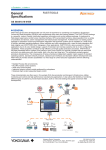
General
Specifications
GS 25G10A01-01EN
Model HXS10
Application Specific Controller
Model HXSS10
Setting Software for HXS10
TM
[HXS10 Application Specific Controller]
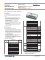
▌GENERAL
The HXS10 is a general-purpose controller with a
function to calculate solar position for the new energy
market.
• Up to 6 analog and 12 digital inputs, and up to 2
analog and 12 digital outputs are available
• Up to 2 pulse counter (encoder) inputs are available
• Ethernet, RS-232, and RS-485 communication
options are available
• Control function allows for creating internal
calculations to support various applications
• Two proven programming methods of the YS series,
function block programming and text programming,
are available
• Sophisticated PID calculation functions of the YS
series are available
● User Programming Function
The user programming function allows for performing
calculations for analog, digital, and pulse counter
input values, or values from communication, as well
as internal parameter values, and storing the results
as analog, digital, and communication output values,
or as internal parameters.
The use of HXSS10 Setting Software for PC allows
for creating calculations.
Two programming methods, function block
programming and text programming, are available.
The following basic calculations can be used with the
following computation modules.
Computation Module List
Module Name
Basic Computations
Addition
Subtraction
Multiplication
Division
Square root extraction (no hysteresis)
Absolute value
High selector
Low selector
High limiter
Low limiter
Natural logarithm
Common logarithm
Exponential
Power
Temperature compensation
Pressure compensation
Scaling
Normalization
Ratio
Conversion from DI to BCD
Max.
number
of times
of use
(*1)
Unlimited
Computation Modules with Serial Number
▌FEATURES
Conversion from BCD to DO
Conversion from DI to binary
Conversion from binary to DO
Maximum
Minimum
Average
Increment
Decrement
trigonometric function
Bit operation
10-segment linearizer function
Inverse conversion of 10-segment
linearizer function
Arbitrary segment linearizer function
Inverse conversion of arbitrary
segment linearizer function
Segment linearizer bias
High limit alarm
Low limit alarm
First-order lag (2 kinds: second, minute)
Derivative (2 kinds: second, minute)
Dead time (2 kinds: second, minute)
Velocity computation (2 kinds: second,
minute)
Moving average computation (2 kinds:
second, minute)
Velocity limiter
Timer (2 kinds: second, minute)
Time out (2 kinds: second, minute)
Hold timer (2 kinds: second, minute)
Delay timer (2 kinds: second, minute)
Change detection
Square root extraction (Low cutoff point
or less: Linear) (*2)
Square root extraction (Low cutoff point
or less: Zero) (*2)
RS flip-flop
Previous input variable
Hold
Logical
AND
Operations OR
Exclusive OR
NOT
Conditional Comparison
Judgement Comparison of time
Signal switching
Jump (*3)
Conditional jump (*3)
Jump to sub-program
Control
Basic control
Functions
Others
S register change (*3)
S register rotation (*3)
Unlimited
Unlimited
Unlimited
Unlimited
Unlimited
8
8
8 each
2 each
3 each
3 each
3 each
6
16
16
16
16
32
8
each
each
each
each
x3
8
32
16
16
Unlimited
Unlimited
2
Unlimited
*1: Limitation when used within the limit of programming
capacity. There is the maximum number of times of use for
modules that use buffers such as that for the previous value.
*2: Hysteresis exists at low cutoff point.
*3: Unavailable in function block programming.
GS 25G10A01-01EN
©Copyright June 2010
4th Edition Jun. 13, 2011
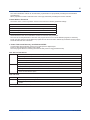
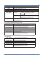
Handling of Input/Output Signals
The user programming uses 32-bit floating-point operations.
Inputs/Outputs from Terminals
Analog input (AI)
0 to 100% input in the analog input range (RLn to RHn) is stored in Xn (n = 1 to 6)
as a floating-point number from 0.0 to 1.0.
Analog output (AO)
Storing a floating-point number from 0.0 to 1.0 in Yn (n = 1 to 2) outputs an analog
signal in the range from 0 to 100%.
Digital input (DI)
17 V or more voltage input or closed contact is stored in DIn (n = 1 to 12) as a
floating-point number 1.0.
4 V or less voltage input or open contact is stored in DIn (n = 1 to 12) as a floatingpoint number 0.0.
Digital output (DO)
Pulse counter (encoder)
input
Storing 0.5 or more in DOn (n = 1 to 12) closes the contact and storing less than
0.5 opens the contact.
Value converted from the count value range (EnZCNT to EnSCNT) to the angle
range (EnZANG to EnSANG) is stored in En (n = 1 to 2).
Xn, DIn, and En are updated in the stop state. For Yn and DOn, the last state is held
Inputs/Outputs from Communication
CX and CY are holding registers for MODBUS, which hold 32-bit integer numbers or 32-bit floating-point numbers.
Additionally, there are decimal point position parameters CXD and CYD for handling integer numbers. Floating-point
numbers are used in the user programming.
When the HXS10 is a communication
master/client
When the HXS10 is a communication
slave/server
Numerical input
CXn (n = 1 to 250)
Set the following using the PC software HXSS10.
• Register no. of the target Slave/Server
• Data format of the target Slave/Server
• Register no. of CXn which stores the read value
You can write to / read from CXn an arbitrary value
via external communication.
Numerical output
CYn (n = 1 to 250)
Set the following using the PC software HXSS10.
• Register no. of the target Slave/Server
• Data format of the target Slave/Server
• Register no. of CYn which stores the value to write
You can read from CYn a value via external
communication.
Parameters Available in User Programming
• All parameters for control calculations
• All parameters for solar position calculations
• Input/output registers CX and CY from communication, with the exception of scaling parameters.
General-purpose Parameters (Registers) for User Programming:
Operations available for
the user programming
P parameters
(P01 to P200)
• LD (read)/ST (write)
K constants
(K01 to K200)
• LD (read) only
T registers
(T01 to T200)
• LD (read)/ST (write)
Operations available for communication
(when the HXS10 is a slave/server)
• Read/write
Saving to nonvolatile memory
• Saved
• Scaling
• Read/write
• Saved
(can be performed only from HXSS10
Setting Software for PC)
• Read
• Not saved
(can be performed only from HXSS10
Setting Software for PC)
Calculation Period
In the case of no AI or 2 AIs
Calculation Period
100 ms/250 ms
All Rights Reserved. Copyright © 2010, Yokogawa Electric Corporation
In the case of 4 or 6 AIs
250 ms
GS 25G10A01-01EN Jun. 13, 2011-00
User Program Capacity
Refers to the capacity of data that can be described in user programs, including main programs and sub-programs.
Sub-programs can be used repeatedly.
Programming method
Capacity of data that can be described in user programs
Text programming
Up to 1,000 steps
Function block programming
Up to 400 modules when “Application” in Model and Suffix Codes is -01.
Up to 1200 modules when “Application” in Model and Suffix Codes is -02.
User Program Executable Capacity
A user program must be completed within the calculation period.
The execution time of the computation modules used in the user program varies from one to another. Accordingly,
the number of steps or modules that can be executed within the calculation period varies depending on the user
program.
The ratio of the user program's execution time within the calculation period can be checked by the load factor
parameter.
The load factor should be set to 100% or less. A load factor of more than 100% causes an alarm. A load factor
exceeding 200% forcibly stops the user program.
("Denominator of the load factor") =
(("Calculation period") – ("time for input/output, communication, and solar position calculation"))
Debugging Monitoring Function
The use of HXSS10 Setting Software for PC allows
for checking the program online.
A test run function and online module monitoring
function are available.
Solar Position Calculation Function
This function calculates the estimated solar position
based on the latitude, longitude, current date and
time, or the like, using the Solar Position Algorithm
(SPA).
The solar position calculation uses the algorithm
and software of the National Renewable Energy
Laboratory of the United States Department of
Energy.
Parameters necessary for the solar position
calculation include the current time, calculation time
offset in seconds (to estimate the position a few
seconds later), difference from the atomic clock, and
the latitude, longitude, altitude, time zone, annual
average temperature, annual average atmospheric
pressure, and air reflection coefficient of the
installation location.
The calculation results include azimuth angle,
zenith angle, solar angle for the trough mirror/northsouth axis tracker, sunrise time, culmination time,
and sunset time. The calculation results are stored
in parameters and can be referred to in the user
program.
Every time the second hand for the current time
moves forward, the solar position calculation starts,
regardless of the calculation period.
All Rights Reserved. Copyright © 2010, Yokogawa Electric Corporation
Control Calculation Functions
Control Computation Module
The combined use of the control module and each of
the computation modules allows for creating control
calculations. The following shows control computation
modules. One BSC1 and one BSC2 can be used in
the same program.
Basic control modules (BSC1 and BSC2)
Control Types
The control type can be selected by a parameter from
standard PID control and proportional derivative (PD)
control.
Control Parameters
Common Parameters for PID and PD Control
PID control
Proportional band (PB)
0.1 to 999.9 (sec.)
Integral time (TI)
(*1)
1 to 9999 (sec.)
Derivative time (TD)
(*2)
0 to 9999 (sec.)
Parameters Specific to PD Control
PD Control
First-order lag time constant *3 1 to 9999 (sec.)
Manual reset
-6.3 to 106.3 (%)
*1: Needs no setting for PD control.
*2: A setting from 1 to 9999 is effective and 0 means OFF.
*3: To avoid abrupt changes in output when the operation
mode is changed, follow-up actions take place with firstorder lag delay. Set the parameter to an integral time.
GS 25G10A01-01EN Jun. 13, 2011-00
Control Calculation Method
The control calculation method can be selected by a parameter from proportional preceding PID and derivative
preceding PID.
When proportional control is selected for the control type, derivative preceding PID must be selected.
Control Add-on Functions
The actions of the control computation module can be defined in detail by parameter settings.
PID control with reset bias
Output limiters
Alarm detection (HHL, HL, LL, LLL, measurement value change rate, deviation)
Cascade setting input
Preset PID
Alarms detected in the control calculation module are stored in each parameter.
The user can set the parameter to OR in the user program and store it in the ALARM lamp register, if necessary.
Finally, the value stored in the ALARM lamp register and the abnormal state detected by the HXS10 are set to OR to
set the ALARM LED to the ON state.
● Power Failure and Recovery, and RUN and STOP
A power failure sets the analog output to 0 mA and opens the digital output.
Power on sets the RUN and STOP mode to RUN.
The user program allows for checking the first-time-after-power-on flag (parameter PON).
HOT Start and COLD Start
HOT start
The state at the time of a power failure is backed up and that value is used to continue operation.
The following is backed up
• AO value
• Control mode (C, A, and M)
• Buffers, such as that for the previous value of the computation module with user program serial number
COLD start
Always starts operation in the same state, regardless of the state at the time of a power failure.
• AO starts from -25% (however, the output LL from the output terminal is 0 mA.)
• Starting control mode is M.
• The previous value of the computation module with user program serial number is initialized to zero or the current
value in the first calculation period.
RUN and STOP
RUN
• RUN is a state in which the user program is executed.
STOP
• The user program is not running.
• The input, clock, solar position calculation, and communication are operable, which means Xn, DIn, and the like are
updated.
• Switching STOP to RUN outputs the previous value. Other than that, the output remains the same as with the COLD start.
All Rights Reserved. Copyright © 2010, Yokogawa Electric Corporation
GS 25G10A01-01EN Jun. 13, 2011-00
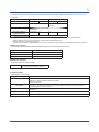
Data Types and backed up
Data
With or without backup
Without backup
Initial values at the time of COLD start
0.0, 0 (open)
-25.0%, 0 (open)
CX
With backup
at every calculation period
Without backup
CY
Without backup
0
P
With backup
every time changed
With backup
every time changed
With backup
at every calculation period
With backup
every time changed
With backup
every time changed
With backup
Backup value
With backup
Current time (also applies to the HOT start)
Solar position calculation
result
Without backup
Undefined until the calculation result valid
flag is set (also applies to the HOT start)
Each alarm
With backup
at every calculation period
With backup
at every calculation period
Alarm OFF
X, DI
Y, DO
K
T
Control parameter
Control's internal register
Previous value of the
computation module with user
program serial number, etc.
Date/time
E
0
Backup value
0
Backup value
Backup value
Varies depending on the module.
Backup value
● Self Diagnosis
Diagnostic
Result
FAIL
ALARM
Cause
Remarks
•Main CPU failure
•A/D converter problem
•Memory error
•Control period exceeded
•Computation overflow
•User program error
At Fail, both DO12 and FAIL
indicators are activated.
● Security Functions
Security functions available in HXSS10
• Users can set password on an user defined program from the PC software HXSS10.
• When a password is not set in an user program, you can upload / download the program from the PC software HXSS10.
• When a password is set in an user program, HXSS10 software ask you to type in password prior to upload / download. Once the
password matches, you can upload / download the program from the PC software HXSS10.
• There is a password lock function for output files (with the extension .hss) of HXSS10 Setting Software for PC.
Communication Security Function
•Modbus/TCP can be set to reject access from any address other than specified IP addresses (up to 10).
All Rights Reserved. Copyright © 2010, Yokogawa Electric Corporation
GS 25G10A01-01EN Jun. 13, 2011-00
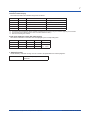
● Communication Functions
The following describes the standard communication between the HXS10 and other devices, such as a PC, PLC,
and DCS.
Type
Modbus/TCP
Method
Interface
Connected devices
Maximum number of
connected devices
*
Server
Modbus (RTU)
Client
• Ethernet
Master
Slave
• RS-485
• RS-232
• External devices, such as a PC
• Inter-HXS10
4 (connection) 10
31
1
Communication data
Measured value, setpoint, output value, and alarm
Client/Master Specifications
Communication period: 100 ms, 250 ms, 500 ms, 1 sec, 2 sec, 5 sec (not synchronized to the control calculation period)
Modbus master can issue upto 200 commands for both RS232 and RS485 combined.
Modbus client can issue up to 200 commands.
The data types accessible through Modbus are the following. 16-bit integer, 32-bit integer, 32-bit floating-point, and bit (coil and DI).
SNTP Client Function
This function checks the time with the specified SNTP server and synchronizes the time.
Specifiable number of servers
Check period
1
Can be selected from 3, 6, 12, or 24 hours
Reference time
The reference time to be checked can be set
Timeout time
Can be selected from 1 to 60 sec
SNTP Server Function
Runs the HXS10 as a SNTP server.
Port number
123 (factory initial value).
The value can be changed by the user.
●Clock Function
With calendar function (AD)
Clock accuracy
Time setting
±100 ppm (in the entire temperature range)
• Set from HXSS10
• Set from an upper-level device (write to the register)
• SNTP client function
Clock adjustment method
using SNTP
When an user program is running, time adjustment with the SNTP server will not be executed
if deviation is 10 minutes or more. When an user program is stopped, time synchronization is
executed regardless of the deviation.
Time zone
Setting of time difference from Greenwich Mean Time: -18.00 to 18.00 (can be set in minute
increments)
Time range
January 1, 2001, to December 13, 2037
Summertime
Available
All Rights Reserved. Copyright © 2010, Yokogawa Electric Corporation
GS 25G10A01-01EN Jun. 13, 2011-00
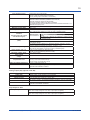
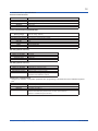
● Display Functions
Instrument status display
The instrument status is indicated using LEDs as follows:
LED Name
LED Color
ON
OFF
READY
Green
Normal condition
Failure (*1) / Power OFF
RUN
Green
Under operation
Stopped condition (*2)
ALARM
Yellow
Alarm is detected
No Alarm
COMM ERR
Yellow
Communication error detected (*3)
Communication is functioning
FAIL
Red
FAIL detected (*4)
No FAIL
*1:
*2:
*3:
*4:
The unit is not functioning properly. (e.g. due to power supply failure )
The HX-S is being configured by the PC software. During the test run mode (running the simulation program), the LED blinks.
Communication error: Blinking (when an error occurred in Modbus or SNTP.)
Refer to the Self Diagnosis Feature
Digital input (DI)/digital output (DO) status display
The status of ON/OFF of each DIO can be displayed by the corresponding LED.
LED Name
LED Color
Lit
Unlit
DI1 to DI12
Red
ON
OFF
DO1 to DO11
Red
ON
OFF
DO12
Red
ON (*1)
OFF
Remarks
ON: CLOSE
OFF: OPEN
*1 At Fail, both DO12 and FAIL indicators are activated.
● Setting Function
HXSS10 Setting Software running on a PC is used to set parameters and create programs.
Connection method
• HXSS90 Proprietary cable for HXS10
• Ethernet
All Rights Reserved. Copyright © 2010, Yokogawa Electric Corporation
GS 25G10A01-01EN Jun. 13, 2011-00
▌FUNCTION BLOCK DIAGRAM
DC voltage, Standard signal
Thermocouple, and RTD
Contact input
Pulse counter input
(Encoder input)
Input
section
A/D conversion
Unsynchronized with
the control period.
Burnout
Date/time parameters
Linearize
Communication
section
Range calculation
Over range judgement
Xn
DIn
En
LD instruction
LD instruction
LD instruction
CXn communication input
S1 to S5 computation registers
User program
Pn variable parameters
Tn temporary memory registers
Kn constant registers
Yn
Repeated
at each
control
period
Range calculation
RJC error judgement
ST instruction
Solar position calculations
section
Solar position calculations
User program
section
Solar position calculation result
Control operation parameters
Control operation internal registers
ST instruction
DOn
CYn communication output
LED lamp registers
Output
section
D/A conversion
4-20mA
Contact output
All Rights Reserved. Copyright © 2010, Yokogawa Electric Corporation
LED lamp
GS 25G10A01-01EN Jun. 13, 2011-00
▌HARDWARE SPECIFICATIONS
● Input/Output Specifications
Analog Input (AI)
•Number of Universal Inputs: Max. 6 (M3 screw terminal)
•Input range: -5% to 105% (The guaranteed accuracy range is 0% to 100%.)
•Input type, instrument range, and measurement accuracy: See the table below,
Input Type
DC
voltage
Standard
signal
Thermocouple (*1)
RTD
J
T
Range name
(Range code)
20 mV (0)
60 mV (1)
200 mV (2)
1 V (3)
2 V (4)
6 V (5)
0-10 V (6)
20 V (7)
0.4-2 V (8)
1-5 (9)
K1 (10)
K2 (11)
J (12)
T (13)
-20.000 to 20.000 mV
-60.00 to 60.00 mV
-200.00 to 200.00 mV
-1.0000 to 1.0000 V
-2.0000 to 2.0000 V
-6.000 to 6.000 V
0.000 to 10.000 V
-20.000 to 20.000 V
0.4000 to 2.0000 V
1.000 to 5.000 V
-270.0 to 370.0°C
-450.0
-200.0 to 500.0°C
-200.0
-200.0 to 1100.0°C -300.0
-270.0 to 400.0°C
-450.0
B
B (14)
0.0 to 1800.0°C
32 to 3300°F
S
R
N
S (15)
R (16)
N (17)
0.0 to 1700.0°C
0.0 to 1700.0°C
-200.0 to 1300.0°C
32 to 3100°F
32 to 3100°F
-300.0 to 2400.0°F
E
L
U
E (18)
L (19)
U (20)
-270.0 to 800.0°C
-200.0 to 900.0°C
-200.0 to 400.0°C
-450.0 to 1450.0°F
-300.0 to 1600.0°F
-300.0 to 750.0°F
W
Platinel 2
PR20-40
W (21)
PL2 (22)
P2040 (23)
0.0 to 2300.0°C
0.0 to 1390.0°C
0.0 to 1900.0°C
32 to 4200°F
32.0 to 2500.0°F
32 to 3400°F
W97Re3W75Re25
JPt100
WRe (24)
0.0 to 2000.0°C
32 to 3600°F
20 mV
60 mV
200 mV
1V
2V
6V
0-10 V
20 V
0.4-2 V
1-5 V
K
Measurable range
Accuracy
±0.05% of instrument range ±1 µV
±0.05% of instrument range ±10 µV
±0.05% of instrument range ±0.1 mV
to
to
to
to
2500.0°F
1000.0°F
2000.0°F
750.0°F
±0.05% of instrument range ±1 mV
±0.1% of instrument range ±1 mV
±0.05% of instrument range ±1 mV
±0.1% of instrument range ±0.1 mV
±0.1% of instrument range ±1 mV
± 0.1% of instrument range ± 0.1°C
for 0°C or more
± 0.2% of instrument range ± 0.1°C
for less than 0°C
± 2% of instrument range ± 0.1°C
for less than -200°C of thermocouple K, T.
± 0.15% of instrument range ± 0.1°C
for 400°C or more
± 5% of instrument range ± 0.1°C
for less than 400°C
± 0.15% of instrument range ± 0.1°C
± 0.1% of instrument range ± 0.1°C
for 0°C or more
± 0.25% of instrument range ± 0.1°C
for less than 0°C
± 0.1% of instrument range ±0.1°C
for 0°C or more
± 0.2% of instrument range ± 0.1°C
for less than 0°C
± 1.5% of instrument range ± 0.1°C
for less than -200°C of thermocouple E.
± 0.2% of instrument range ± 0.1°C
± 0.1% of instrument range ± 0.1°C
± 0.5% of instrument range ± 0.1°C
for 800°C or more
Accuracy is not guaranteed
for less than 800°C
± 0.2% of instrument range ±0.1°C
JPT1 (25)
-200.0 to 500.0°C
-300.0 to 1000.0°F ± 0.1% of instrument range ± 0.1°C (*2)
JPT2 (26)
-150.00 to 150.00°C -200.0 to 300.0°F
± 0.1% of instrument range ± 0.1°C
Pt100
PT1 (27)
-200.0 to 850.0°C
-300.0 to 1560.0°F ± 0.1% of instrument range ± 0.1°C (*2)
PT2 (28)
-150.00 to 150.00°C -200.0 to 300.0°F
± 0.1% of instrument range ± 0.1°C
K,J,T,B,S,R,N,E:IEC584-1(1995) DIN IEC584 JIS C1602-1995
U: Cu-CuNi,DIN43710, L:Fe-CuNi,DIN43710
W:W-5% Re/W-26% Re(Hoskins Mfg.Co.),ASTM E988
W97Re3-W75Re25: W-3%Re/W-25%Re (Hoskins Mfg. Co.)
Pt100:JIS C1604-1997 IEC751-1995 DIN IEC751-1996
JPt100:JIS C1604-1989 JIS C1606-1989 Measuring current i=1 mA
• The accuracy is that in the standard operating conditions: 23±2°C, 55±10%RH, and power voltage at 24 VDC ±10%.
*1: Excluding reference junction compensation errors.
*2: ±0.4°C in the range between 0 and +100°C, ±0.6°C in the range between -100 to +200°C, ±0.8°C in the range between +200 to
+500°C
All Rights Reserved. Copyright © 2010, Yokogawa Electric Corporation
GS 25G10A01-01EN Jun. 13, 2011-00
10
Input sampling period
Burnout detection
Input bias current
Measured current (RTD)
Input resistance
Allowable signal source
resistance
(Thermocouple, DC voltage
and Standard signal)
Allowable wiring resistance
(RTD)
Allowable input voltage
Noise rejection ratio (*1)
Maximum common mode
noise voltage
Maximum inter-channel noise
voltage
Reference junction
compensation error
Effect of ambient temperature
External connection
Synchronous with control period
100 ms or 250 ms (Analog Input 2 channels)
250 ms (Analog Input 4 channels or 6 channels)
•Functions at TC, RTD, and standard signal.
•Detection ON/OFF switchable (settable for each channel)
•Upscale, downscale, and off can be specified.
•If “OFF” is specified, analog input value is undefined.
•For standard signal, burnout is determined to have occurred if it is less than 0.1 V.
•Detection time (max): 2 sec.
10 nA or less (except the case of setting burnout detection)
About 1 mA
10 MΩ or more ( for TC / DC voltage (1 V range or less))
About 1 MΩ (for DC voltage (2 V range or more) / standard signal)
2 kΩ or less
Effects of signal
±10 µV/1 kΩ or less (for TC / DC voltage (1 V range or
source resistance
less))
±0.15%/1 kΩ or less (for DC voltage (2 V range or more)
/ standard signal)
Max. 10 Ω/wire (The conductor resistance between three wires shall be equal.)
Wiring resistance effect: ±0.1°C/10 Ω (The conductor resistance between three
wires shall be equal.)
The variation due to a difference in resistance between conductors, 40 mΩ
(maximum difference between three wires), is approx. 0.1°C.
±10 V DC (for TC / DC voltage (1 V range or less) / RTD input)
±30 V DC (for DC voltage (2 V range or more) / standard signal)
40 dB or more (at 50/60 Hz) (Normal mode)
120 dB or more (at 50/60 Hz) (Common mode)
250 V ACrms or less
250 V ACrms or less
±1.5°C (15 to 35°C)
±2.0°C (-10 to 15°C and 35 to 50°C)
±2.5°C (-20 to -10°C and 50 to 70°C)
±0.01% of instrument range /°C
M3 screw terminal (tightening torque: 0.6 N·m)
Applicable wires:AWG26 to AWG18
*1: With digital filter set
Analog Output (AO) (optional code /AA)
Number of outputs
Output type
Load resistance
Output accuracy
Effect of ambient temperature
External connection
2 (M3 screw terminal)
Current output: 4 to 20 mA DC or 0 to 20 mA DC
600 Ω or less
±0.1% of span (±5% of span for 1 mA or less)
The accuracy is that in the standard operating conditions: 23±2°C, 55±10%RH.
±0.02% of F.S./°C or less
M3 screw terminal (tightening torque: 0.6 N·m)
Applicable wires:AWG26 to AWG18
Step Response Time
Step Response Time
Within 500 ms (for computation period 100 ms) (63% of analog output response
time when a step change of 10 to 90% of input span is applied)
Within 1.5 s (for computation period 250 ms) (63% of analog output response
time when a step change of 10 to 90% of input span is applied)
All Rights Reserved. Copyright © 2010, Yokogawa Electric Corporation
GS 25G10A01-01EN Jun. 13, 2011-00
11
Digital Input (DI)
Number of inputs
Input type
Insulating
Rated current (input)
Rated input voltage
Input voltage
Input resistance
ON/OFF detection
External connection
12
DC voltage input (used for sink and source), open collector or no-voltage contact input
(External DI-driven power supply)
Photo-coupler isolation (internal circuit – input)
About 1.4 mA /1 digital input
24 V DC
20.4 to 26.4 V DC
About 16.5 kΩ
Voltage input
On-voltage / 17 V DC or more / 1 mA or more
On-current
Off-voltage / 4 V DC or less / 250 µA or less
Off-current
Open collector input
Input voltage of 2 V DC or less is determined as “ON” and
leakage current must not exceed 250 µA when “OFF.”
No-voltage contact input Contact resistance of 1 kΩ or less is determined as “ON” and
contact resistance of 100 kΩ or more as “OFF.”
2.54 mm-pitch clamp terminal
(recommended tightening torque: 0.12 – 0.15 N·m)
Applicable wires: 0.14 to 0.5 mm2 (AWG26 to AWG20)
Stripped wire length: 4.5 mm
Pulse counter Input (Encoder Input) (optional code /PC)
Number of channels
Input pulse method
Input pulse rate
Corresponding encoder
output
Rated input voltage
Rated input current
On-voltage / On-current
Off-voltage / Off-current
External connection
2 channels
Incremental encoder
10000 (pulse/s) (phase A/phase B (single multiplication))
20000 (pulse/s) (phase A/phase B (double multiplication))
40000 (pulse/s) (phase A/phase B (quad multiplication))
Complementary output (push/pull) / Differential output
24 V±20% (19.2 to 28.8 V : operating voltage range)
5 mA or less
14 V DC or more / 1.6 mA or more
2 V DC or less / 0.25 mA or less
2.54 mm-pitch clamp terminal
(recommended tightening torque: 0.12 – 0.15 N·m)
Applicable wires: 0.14 to 0.5 mm2 (AWG26 to AWG20)
Stripped wire length: 4.5 mm
Digital Output (DO)
Number of outputs
Output type
Isolation method
Rated load voltage
Maximum load current
On-voltage
Leakage current at OFF
External power supply
External connection
12 (Note : DO12 is used for DO12 and FAIL output.)
Transistor contact output (SINK: Share a common wire with the external power
supply)
Photo-coupler isolation (internal circuit – input)
Lower than the external power supply voltage
100 mA / one DO
0.6 V DC or less
0.1 mA or less
12 to 24 V DC (10.2 to 26.4V DC) 20 mA or more
2.54 mm-pitch clamp terminal
(recommended tightening torque: 0.12 – 0.15 N·m)
Applicable wires: 0.14 to 0.5 mm2 (AWG26 to AWG20)
Stripped wire length: 4.5 mm
All Rights Reserved. Copyright © 2010, Yokogawa Electric Corporation
GS 25G10A01-01EN Jun. 13, 2011-00
12
● Communication Specifications
Ethernet Communication
Communication standard
Transmission type
Rate
Connector type
Segment
Protocol
compliant with IEEE 802.3
10 BASE-T / 100 BASE-TX
10/100 Mbps (automatic)
RJ-45
100 m max
Modbus/TCP client, Modbus/TCP server, SNTP client and SNTP server
Serial Communication (RS-232/RS-485)
Address setting
(Setting Range)
Rate
Communication method
Data length
Start bit
Stop bit
Parity
Protocol
1 to 247 (RS-485) , fixed 1 (RS-232)
(Use the setting software)
1200/2400/4800/9600/19200/38400/57600/115200 bps
Asynchronous communication method
8 bit
1 bit
1 bit/2 bits
ODD/EVEN/NONE
Modbus RTU master or Modbus RTU slave
RS-232 (optional code /C2)
Network topology
Modes of operation
Hardware handshaking
Connector type
Maximum distance
1:1
full-duplex
none
DSUB-9pin
max. 15 m
RS-485 (optional code /C3)
Network Topology
Modes of operation
Maximum distance
Terminating resistors
External connection
1:n multidrop, max. n=31
Half-duplex by using two wires
1.2 km max
External (220 Ω, 1/4 W or more)
M3 screw terminal (tightening torque: 0.6 N·m)
Applicable wires:AWG26 to AWG18
Maintenance communication
Using the PC software, configuration parameter data, programming, F/W download can be realized through this
port.
Number of ports
Connector
Cable
Interface
Supported Driver OS
1
Micro-USB (Micro-B)
USB-TTL conversion cable (HXSS90)
Compliant with USB1.1
Windows XP Professional (Service Pack2 or later) (32 bit version)
Windows Vista Business (Service Pack1 or later) (32 bit version)
Windows 7 Professional (32 bit version)
All Rights Reserved. Copyright © 2010, Yokogawa Electric Corporation
GS 25G10A01-01EN Jun. 13, 2011-00
13
● Power Supply Specifications and Isolation
Power Supply Specifications
Rated voltage
Power consumption
Power holdup time
24 V DC±10%
5 W or less
1 ms or less
Isolation
•Withstanding voltage
Among AI input channels
Between analog input and
internal circuits
Between analog input and
external circuits
Between power supply and
other circuits
Between internal and
external circuits
Among other circuits
1500 V AC for 1 minute
1500 V AC for 1 minute
1000 V AC for 1 minute
1000 V AC for 1 minute
Analog Input 1
Analog Input 2
Analog Input 3
Analog Input 4
Analog Input 5
Analog Input 6
Analog Output 1
Analog Output 2
Digital Input 1 to 12
External power supply
Digital Output 1 to 12
External power supply
RS485 communication
(Except FG terminal)
Pulse Counter Input 1
(Except FG terminal)
Pulse Counter Input 2
(Except FG terminal)
Ethernet communication
External circuits
Internal circuits
Power supply (24 V DC)
•RS232
communication
•Maintenance
communication
•FG terminal
1000 V AC for 1 minute
1500 V AC for 1 minute
•Insulation resistance
Between FG terminal
(internal circuit) and
other circuits
20 MΩ or more (500 V DC)
All Rights Reserved. Copyright © 2010, Yokogawa Electric Corporation
GS 25G10A01-01EN Jun. 13, 2011-00
14
● Environmental Conditions
Item
Ambient
temperature
Ambient
humidity
Temperature
change rate
Continuous
vibration
Short-period
vibration
Shock
Magnetic field
Warm-up time
Toxic gas
Altitude
Normal Operating Conditions
-20 to 70°C
Transportation and Storage
Conditions
-25 to 70°C
20 to 90%RH
5 to 95%RH
10°C/h or less
20°C/h or less
Half amplitude: 0.075 mm (frequency : 10 to 57 Hz)
Acceleration:9.8 m/s2 (frequency : 57 to 150 Hz)
Sweep cycle count in X, Y, and Z directions: 10 times
14.7 m/s2
15 sec. or less
Energized: 98 m/s2 or less
When contained in external
packing (blue box) 90 cm or less
Non-energized: 147 m/s2 or less
Remarks
(no condensation
allowed)
Impact time
11 ms or less
Three times each in X, Y, and Z
directions with half-sine shock pulse
400 A/m or less
30 minutes or more after the power is turned on
Location free of corrosive gases
2000 m or less above sea level
● Safety and EMC Standards
CE, C-Tick
Safety
IEC61010-1 and EN61010-1.
Installation category
Pollution degree
Measurement category
Rated measurement input
voltage
Rated transient
overvoltage
*
CAT I
2
I (CAT I)
±30 V DC max.
1500 V (*)
This is a reference safety standard value for Measurement Category I of IEC/EN61010-1.
This value is not necessarily a guarantee of instrument performance.
EMC
CE marking
EN61326-1 Class A, Table2
EN61326-2-3
EN55011 Class A Group1
C-Tick mark
EN55011 Class A Group1
The instrument continues to operate at a measurement accuracy of within ±10% of the range during testing.
Environmental resistance
Compliant with RoHS, WEEE
● Structure
Dust-proof and drip-proof
Material
Color
Weight
External dimensions (mm)
Installation
Mounting direction
IP20
Steel plate (Case)
Polyacetal resin (DIN rail mounting brackets)
Light gray
About 1.0 kg
226×132× (67) (excluding DIN rail mounting brackets)
Wall mounting or DIN rail mounting
For wall mounting, mount the instrument with four M4 screws.
The product uses air cooling without blower. Install it with the front facing you and
in the correct horizontal and vertical directions.
All Rights Reserved. Copyright © 2010, Yokogawa Electric Corporation
GS 25G10A01-01EN Jun. 13, 2011-00
15
▌EXTERNAL DIMENSIONS
(67.1)
226.2
M3 screw terminals
Clamp terminals
Unit: mm
(15)
4-ø4.5 holes
(7)
DIN rail
31.4
132
118
(8.4)
(114)
7
8.2
209.6
79.2
If not specified, the tolerance is ±3%. However, in cases of less than 10 mm, the tolerance is ±0.3 mm.
Mounting dimension diagram
Non-heat generating
devices
Non-heat generating devices
30 or more
Unit: mm
30 or more
4-M4 screw holes
(for wall mounting)
118±0.2
HXS10
209.6±0.2
10 or more (*)
Non-heat generating devices
Non-heat generating devices
50 or more
10 or more (*)
80 or more
*When there is the heat generating device,
keep at least a 50 mm space between
the HXS10 and the heat generating device
Non-heat generating devices
HXS10
80 or more
Non-heat generating
devices
This instrument should be well spaced out as shown in the mounting dimensions.
Do not install HXS10 to the location just above the high-heat-generating equipment.
All Rights Reserved. Copyright © 2010, Yokogawa Electric Corporation
GS 25G10A01-01EN Jun. 13, 2011-00
16
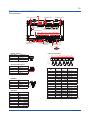
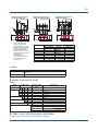
▌TERMINAL ARRANGEMENT
Terminal Diagram
Pulse counter input 2
AO (Analog output)
Pulse counter input 1
1
8 1
8
DI (Digital input)
1 2 3 4
1
DO (Digital output)
16 1
16
LED
Instrument status display
LED
LED
DI status display DO status display
AI (Analog input)
CH1
CH2
CH3
CH4
CH5
CH6
1 2 3 4 5 6 7 8 9 10 11 12 13 14 15 16 17 18
Power supply 1 2 3
24 V DC±10%
Maintenance
communication
RS-485 (SETUP)
1 2 3 4
Ethernet
RS-232
DSUB-9pin (male)
12345
67 89
< Power supply >
Terminal No.
1
2
3
Function
24 V DC +
24 V DC FG
< Analog input (AI) >
1 2 3
CH1
CH2
CH3
CH4
CH5
CH6
1 2 3 4 5 6 7 8 9 10 11 12 13 14 15 16 17 18
– FG
+
TC
24 V DC
mV/V
< RS-485 >
Terminal No.
1
2
3
4
< RS-232 >
Terminal No.
1
2
3
4
5
6
7
8
9
0-20 / 4-20 mA
CH1 (+)
CH1 (-)
CH2 (+)
CH2 (-)
Function
FG
RSB (+)
RSA (-)
SG
–
–
+
+
–
–
+
+
– +
– +
–
–
+
+
–
–
+
+
–
–
RTD A B b A B b A B b A B b A B b A B b
< Analog output (AO) >
Terminal No.
1
2
3
4
+
+
+ –
+ –
1 2 3 4
CH1 CH2
1 2 3 4
FG
RSB(+)
SG
RSA(–)
Function
RxD
TxD
SG
All Rights Reserved. Copyright © 2010, Yokogawa Electric Corporation
Terminal
No.
TC
mV / V
RTD
1
CH1 (+)
CH1 (+)
CH1 (A )
CH1 (-)
CH1 (B )
2
CH1 (-)
3
CH1 (b)
(*1)
4
CH2 (+)
CH2 (+)
CH2 (A )
5
CH2 (-)
CH2 (-)
CH2 (B )
6
CH2 (b)
(*1)
7
CH3 (+)
CH3 (+)
CH3 (A )
8
CH3 (-)
CH3 (-)
CH3 (B )
9
CH3 (b)
(*1)
10
CH4 (+)
CH4 (+)
CH4 (A )
11
CH4 (-)
CH4 (-)
CH4 (B )
12
CH4 (b)
(*1)
13
CH5 (+)
CH5 (+)
CH5 (A )
14
CH5 (-)
CH5 (-)
CH5 (B )
15
CH5 (b)
(*1)
16
CH6 (+)
CH6 (+)
CH6 (A )
17
CH6 (-)
CH6 (-)
CH6 (B )
18
CH6 (b)
(*1)
*1: RTD terminal b is shorted internally across all channels.
GS 25G10A01-01EN Jun. 13, 2011-00
17
< Digital input (DI) >
< Digital output (DO) >
(*1)
(*1)
L L L L L L L L L L L L
3
4
5
6
7
8
1
2
3
4
5
6
7
8
9 10 11 12 13 14 15 16
DI9
DI10
DI11
DI12
COM1
COM1
COM2
COM2
DI1
DI2
DI3
DI4
DI5
DI6
DI7
DI8
DO1
DO2
DO3
DO4
DO5
DO6
DO7
DO8
2
9 10 11 12 13 14 15 16
DO9
DO10
DO11
DO12
VDO
VDO
COMDO
COMDO
(*2)
1
*1: Input power has no polarity.
*2: The instrument can operate even if no COM2 is connected.
DI1
DI2
DI3
DI4
DI5
DI6
DI7
DI8
Terminal
No.
9
10
11
12
13
14
15
16
Function
DI9
DI10
DI11
DI12
COM1
COM1
COM2
COM2
• When the load voltage is lower than the external
power supply voltage
VL
(for
(for
(for
(for
DI)
DI)
DI)
DI)
(*1)
VDO
L L L L L L L L L L L L
1
2
3
4
5
6
7
8
9 10 11 12 13 14 15 16
DO9
DO10
DO11
DO12
VDO
VDO
COMDO
COMDO
Function
DO1
DO2
DO3
DO4
DO5
DO6
DO7
DO8
1
2
3
4
5
6
7
8
Terminal
No.
output circuit
Observe the following:
VDO ≧ VL
output circuit
*1: Ensure the polarity of VDO and COMDO for the wiring.
To protect output circuit in case of reversed wiring,
provide fuse to external circuit and reduce incoming
electric current to the HXS10 to 100 mA or less.
1
2
3
4
5
6
7
8
All Rights Reserved. Copyright © 2010, Yokogawa Electric Corporation
Terminal
No.
Function
DO1
DO2
DO3
DO4
DO5
DO6
DO7
DO8
Terminal
No.
9
10
11
12
13
14
15
16
Function
DO9
DO10
DO11
DO12
VDO
VDO
COMDO
COMDO
GS 25G10A01-01EN Jun. 13, 2011-00
18
< Pulse counter input (Encoder Input) 1, 2 >
Example of connection to
voltage (Push-Pull) output
encoder-side
Example of connection to
opencollector output
encoder-side
+24V
A
Z
B
C
A
+24V
B
Example of connection to
differential output
encoder-side
+24V
Z C
A /A B /B Z /Z C
+24V COM
1
2
3
4
5
6
A
B
Z
HXS10 /A /B /Z
7
8
1
2
3
4
5
6
A
B
Z
HXS10 /A /B /Z
FG
* In the case of an open
collector type encoder,
the calculation may not be
normally performed by the
capacity coupling between
phase A and phase B.
When using, connect them
separating each phase with
shielded wires.
The shield must be
connected to the common
24 V power supply for
encoder input.
Terminal No.
1
2
3
4
5
6
7
8
7
8
1
2
3
4
5
6
A
B
Z
HXS10 /A /B /Z
FG
Function
Opencollector
Voltage
+24V
A
A
COMMON
+24V
B
B
COMMON
+24V
Z (R)
Z
COMMON
FG
7
8
FG
Differential
A
/A
B
/B
Z (R)
/Z (/R)
FG
● Others
Item
Memory backup
Specifications
A built-in lithium battery backs up the setup parameters and runs
the clock
Approximately ten years at room temperature.
Lithium battery life
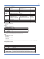
▌MODEL AND SUFFIX CODE
HXS10
Model
HXS10
Analog input
Language
Application
Fixed code
Options
Suffix code
Optional suffix
code
-0
-2
-4
-6
-1
-2
-01
-02
-00
/AA
/C2
/C3
/PC
Description
Application specific controller
None
2 channels
4 channels
6 channels
Japanese
English
for Solar tracking
for Solar tracking (Extended memory)
Always "00"
Analog output (2ch)
RS-232 communication
RS-485 communication
Pulse counter input (2 channels)
▌ITEMS TO BE SPECIFIED WHEN ORDERING
Model, suffix code, and optional suffix codes are required.
All Rights Reserved. Copyright © 2010, Yokogawa Electric Corporation
GS 25G10A01-01EN Jun. 13, 2011-00
19
[HXSS10 Setting Software for HXS10]
▌GENERAL
HXSS10 is package software to set functions for the HXS10. HXSS10 consists of the following software.
HXS10 Setting
Software
HXS10 Multi
Terminal Setting
Software
• This software is connected to one HXS10 with Ethernet or HXSS90 proprietary cable for HXS10 and
can perform tasks via a communication network, such as writing and reading HXS10 parameters
and user programs, PID tuning, and monitoring user programs.
• This software is connected to multiple HXS10 units (up to 1,000) with Ethernet and can batch write
parameters and user programs created with HXS10 Setting Software.
• This software also can set the time all at once.
▌FEATURES
● HXS10 Setting Software
Number of
connected units
Parameter setting
function
User program
creation function
Communication
function
Tuning function
User program
monitoring function
File management
function
Print function
Time setting
function
This software can be connected to and communicate with one HXS10 unit.
This software allows for performing the setting of parameters for the HXS10. The following lists
the main parameters.
Control period
Analog input
• Input type
• Range
Analog output
•Output type
Time
• Time zone
• SNTP setting
• DST setting
Solar position calculation
• Latitude
• Average temperature
• Longitude
• Average pressure
Modbus master / Modbus client
• Period
• Register number
• Connection destination
• Data type
• Read or write selection
PID
• Setpoint
• Integral time
• Proportional band
• Derivative time
Others
• Line segment table
• Constant
This function allows for creating user programs for the HXS10.
User program creation method
• Function block programming
• Text programming
This function allows for writing and reading various parameters and user programs to and from
the HXS10. (Write can be performed only when the HXS10 is not running)
This function allows for performing adjustment of PID parameters. It allows for setting PID
parameters while viewing the PV, SV, and MV trends via communication with the HXS10.
This function allows for performing monitoring while communicating with the HXS10.
• Monitoring various parameters
• Monitoring module input and output values of each module in the function block programming
method
This function allows for saving and reading the setting data to and from a PC.
• Parameter
• User program
This function allows for printing parameters and user programs to the printer.
This function allows for setting the time for the HXS10 via a communication network.
All Rights Reserved. Copyright © 2010, Yokogawa Electric Corporation
GS 25G10A01-01EN Jun. 13, 2011-00
20
● HXS10 Multi Terminal Setting Software
Number of connected units
Transmission of
parameters to
multi-terminals
Transmission of
user programs to
multi-terminals
Transmission of time &
date to multi-terminals
This software can be connected to and communicate with up to 1,000 HXS10 units.
This function allows for batch setting parameters created and saved with HXS10
Setting Software to multiple HXS10 units via a communication network.
This function allows for batch setting user programs created and saved with HXS10
Setting Software to multiple HXS10 units via a communication network.
This function allows for setting the time for multiple HXS10 units via a
communication network all at once.
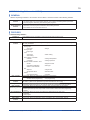
▌OPERATING ENVIRONMENT
● PC
Applicable OS
Required
component
CPU
Main memory
capacity
Hard Drive
Capacity
Display:
Communication
port
CD-ROM Drive
Mouse
• Windows XP Professional (Service Pack2 or later) (32 bit English/Japanese/Spanish version)
• Windows Vista Business (Service Pack1 or later) (32 bit English/Japanese/Spanish version)
• Windows 7 Professional (32 bit English/Japanese/Spanish version)
Note: Strings in the software are displayed in English in the Spanish version.
• .NET Framework 3.5 SP1
• Pentium4 processor, 2.4 GHz or higher recommended
• Pentium4 processor, 3.0 GHz or higher recommended for Windows Vista Business/Windows 7
• Pentium D processor, 2.6 GHz or higher recommended
• Core 2 Duo processor 1.8 GHz or higher recommended
• Pentium Dual-Core processor 1.6 GHz or higher recommended
• Windows XP Professional 512 MB or more
• Windows Vista Business/Windows 7 Professional 2 GB or more
• Package program storage: 100 MB or more
• .NET Framework3.5 SP1 program storage: 620 MB or more
• XGA (1024 x 768 pixels or more), 16 bits colors (65,536 colors) or more
• USB port (used when performing communication using the maintenance port with HXSS90
proprietary cable for HXS10)
• Ethernet port (used when performing communication using the Ethernet port)
One (required for installation)
One (suitable for the OS)
● Printer
Printer
• Printer (suitable for the OS). Paper size: A4
● Connection cable
Connection cable
• Cable compliant with the 10BASE-T/ 100BASE-TX standards (used when performing
communication using the Ethernet port)
• HXSS90 proprietary cable for HXS10 (used when performing communication using the
maintenance port)
All Rights Reserved. Copyright © 2010, Yokogawa Electric Corporation
GS 25G10A01-01EN Jun. 13, 2011-00
21
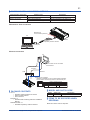
▌COMMUNICATION CONNECTION METHOD
Communication connection
method
Maintenance Port Connection
Ethernet Connection
Software used
Description
HXS10 Setting Software
HXS10 Setting Software
HXS10 Multi Terminal Setting Software
Can be connected to one HXS10 unit
Can be connected to one HXS10 unit
Can be connected to multiple HXS10 units
Maintenance Port Connection
Maintenance
communication (SETUP)
PC
HXS10
HXSS90
Proprietary cable for HXS10
to a USB port
Ethernet connection
PC
* Device that can be connected
over Ethernet
Data transmission/
reception
HUB
Ethernet
Ethernet port of HXS10
10BASE-T/100BASE-TX can be automatically detected,
and the status confirmed by LEDs on the Ethernet port.
LEDs on the Ethernet port
Left LED (Green)
Right LED (Yellow)
Blink
Unlit
Active
10BASE-T
Link up
Lit
Lit
100BASE-TX
▌PACKAGE CONTENTS
CD: x1
• HXSS10 Setting software for HXS10
• USB conversion driver
• User's manual
Manuals: x1
• HXSS10/HXS10 Setting Software Installation
Manual
Dedicated cable: x1
• HXSS90 Proprietary cable for HXS10
All Rights Reserved. Copyright © 2010, Yokogawa Electric Corporation
▌MODEL AND SUFFIX CODE
Model
HXSS10
Suffix code
-0-0
Description
Setting software for HXS10
▌ITEMS TO BE SPECIFIED WHEN
ORDERING
Model and suffix code are required.
GS 25G10A01-01EN Jun. 13, 2011-00
22
[HXSS90 Proprietary Cable for HXS10]
▌GENERAL
HXSS90 is the Dedicated cable for connecting between PC and Maintenance communication port on HXS10.
● Operating environment
Applicable OS
Windows XP Professional (Service Pack2 or later) 32 bit
Windows Vista Business (Service Pack1 or later) 32 bit
Windows 7 Professional 32 bit
● Interface
Compliant with USB 1.1
PC-side
: USB Series A plug
HXS10-side : Micro USB
Cable length : 2.7 m
Note: Directly insert the USB plug into a USB port on
the PC.
● Power supply
▌EMC
CE marking
EN61326-1 Class A, Table2
EN61326-2-3
EN55011 Class Group1
C-Tick mark
EN55011 Class Group1
▌MODEL AND SUFFIX CODE
Model
HXSS90
Supplied from the USB bus power
5 V DC, Ave. 30 mA
Description
Proprietary cable for HXS10
The dedicated cable for HXSS90/HXS10 is included
in the HXSS10/HXS10 Setting Software package.
▌TERMS TO BE SPECIFIED WHEN
ORDERING
● Ambient temperature
0 to 50 °C
● Ambient humidity
Model and suffix code are required.
10 to 90%RH (No condensation)
● Transport and storage conditions
-20 to 65°C, 10 to 90%RH (No condensation)
● Weight
About 90 g
HXSS90 External Dimensions
unit: mm
2250±50
107±1
350±10
27.9±1
Micro USB
HXS10-side
USB series Type-A plug
PC-side
11.3±1
Trademarks
* Microsoft, Windows, Windows XP, Windows Vista, Windows 7 and .NET Framework are either registered
trademarks or trademarks of Microsoft Corporation in the United States and/or other countries.
* Pentium and Core 2 Duo are registered trademarks of Intel Corporation in the United States.
* Ethernet is a registered trademark of XEROX Corporation.
* Other company and product names are trademarks or registered trademarks of their respective companies.
All Rights Reserved. Copyright © 2010, Yokogawa Electric Corporation
Subject to change without notice.
GS 25G10A01-01EN Jun. 13, 2011-00