1
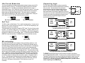
The 7080 contains optical isolation circuitry to prevent the
electrical noise inherent in switching amplifiers from interfering
with your circuits. Optical isolation is accomplished by
powering the motor driver from a different supply than your
circuits. There is no electrical connection between the two:
signal communication is achieved by infrared light. When your
circuit turns on or turns off an infrared LED (built into the drive)
it signals a logic state to the phototransistors that are wired to
the brains of the drive. A schematic diagram of the input
circuit is shown at the right.
50% IDLE
2
50% IDLE
Idle Current Reduction Selected
No Current Reduction
Self Test
The 7080 includes a self test feature. This is used for trouble shooting. If you are unsure
about the motor or signal connections to the drive, or if the 7080 isn't responding to your
step pulses, you can turn on the self test.
To activate the self test, slide switch #1 toward the TEST label. The drive will slowly rotate
the motor, 1/2 revolution forward, then 1/2 rev backward. The pattern repeats until you
slide the switch away from the TEST label. The 7080 always uses half step mode during
the self test, no matter how you set switches 2 and 3. The self test ignores the STEP and
DIRECTION inputs while operating. The ENABLE input continues to function normally.
TEST
Self Test ON
Self Test OFF
+5V OUT
DIR+
DIR
DIR-
STEP–
STEP+
STEP
Drive Input Circuit
7080
Drive
STEP-
Connecting to Indexer with Sinking Outputs
(includes Applied Motion SI-1 Indexer)
PLC
with
Sinking
Outputs
+24V
DIR+
DIR
DIR2200
1/4W
STEP
1
1
TEST
Indexer
with
Sinking
Outputs
inside 7080
STEP+
330½
Connecting Logic
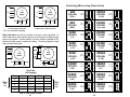
Your drive is equipped with a feature that automatically reduces the motor current by 50%
anytime the motor is not moving. This reduces drive heating by about 50% and lowers
motor heating by 75%. This feature can be disabled if desired so that full current is
maintained at all times. This is useful when a high holding torque is required. To minimize
motor and drive heating we highly recommend that you enable the idle current reduction
feature unless your application strictly forbids it. Idle current reduction is enabled by
sliding switch #2 toward the 50% IDLE label, as shown in the sketch below. Sliding the
switch away from the 50% IDLE label disables the reduction feature.
2
Idle Current Reduction
STEP+
7080
Drive
STEP-
Connecting to PLC with Sinking Outputs
(Most PLC's use 24 volt logic)
Microstepping
Most step motor drives offer a choice between full step and half step resolutions. In full
step mode, both motor phases are used all the time. Half stepping divides each step into
two smaller steps by alternating between both phases on and one phase on. Microstepping
drives like the 7080 precisely control the amount of current in each phase at each step
position as a means of electronically subdividing the steps even further. The 7080 offers a
choice of full and half step as well as 14 other step resolutions. The highest setting divides
each full step into 254 microsteps, providing 50,800 steps per revolution when using a 1.8°
motor. In addition to providing precise positioning and smooth motion, microstep drives
can be used for motion conversion between different units. The 25,400 step/rev setting is
provided as a means of converting motion from metric to english. (There are 25.4 mm in
an inch.) Other settings provide step angles that are decimal degrees (36,000 steps/rev
makes the motor take 0.01 steps.) Some settings are used with lead screws. When the
drive is set to 2000 steps/rev and used with a 5 pitch lead screw, you get .0001
inches/step.
-10-
Indexer
with
Differential
Outputs
DIR+
DIR+
DIR-
DIR-
STEP+
STEP+
STEP-
STEP-
7080
Drive
Connecting to Indexer with Differential Outputs
(Many High Speed Indexers have Differential Outputs)
The ENABLE input allows the user to turn off the current to the motor by providing a
positive voltage between EN+ and EN-. The logic circuitry continues to operate, so the drive
"remembers" the step position even when the amplifiers are disabled. However, the motor
may move slightly when the current is removed depending on the exact motor and load
characteristics. If you have no need to disable the amplifiers, you don't need to
connect anything to the ENABLE input.
-7-