1
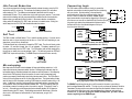
Using the Fault Output
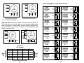
Current Setting Table
0.2
0.4
0.8
1.6
3.2
0.2
0.4
0.8
1.6
3.2
0.2
0.4
0.8
1.6
3.2
3 4 5 6 7
0.2
0.4
0.8
1.6
3.2
3 4 5 6 7
3 4 5 6 7
0.2
0.4
0.8
1.6
3.2
3 4 5 6 7
3 4 5 6 7
0.2
0.4
0.8
1.6
3.2
0.2
0.4
0.8
1.6
3.2
3 4 5 6 7
3 4 5 6 7
0.2
0.4
0.8
1.6
3.2
AMPS/
PHASE
0.2
0.4
0.8
1.6
3.2
3 4 5 6 7
0.2
0.4
0.8
1.6
3.2
5.8
3 4 5 6 7
0.2
0.4
0.8
1.6
3.2
AMPS/
PHASE
0.2
0.4
0.8
1.6
3.2
3 4 5 6 7
0.2
0.4
0.8
1.6
3.2
5.6
3 4 5 6 7
0.2
0.4
0.8
1.6
3.2
3 4 5 6 7
3 4 5 6 7
AMPS/
PHASE
0.2
0.4
0.8
1.6
3.2
3 4 5 6 7
0.2
0.4
0.8
1.6
3.2
4.2
3 4 5 6 7
0.2
0.4
0.8
1.6
3.2
AMPS/
PHASE
0.2
0.4
0.8
1.6
3.2
3 4 5 6 7
0.2
0.4
0.8
1.6
3.2
4.0
3 4 5 6 7
0.2
0.4
0.8
1.6
3.2
3 4 5 6 7
3 4 5 6 7
0.2
0.4
0.8
1.6
3.2
3 4 5 6 7
3 4 5 6 7
0.2
0.4
0.8
1.6
3.2
0.2
0.4
0.8
1.6
3.2
3 4 5 6 7
3 4 5 6 7
0.2
0.4
0.8
1.6
3.2
AMPS/
PHASE
0.2
0.4
0.8
1.6
3.2
3 4 5 6 7
0.2
0.4
0.8
1.6
3.2
2.6
3 4 5 6 7
0.2
0.4
0.8
1.6
3.2
AMPS/
PHASE
0.2
0.4
0.8
1.6
3.2
3 4 5 6 7
0.2
0.4
0.8
1.6
3.2
2.4
3 4 5 6 7
0.2
0.4
0.8
1.6
3.2
3 4 5 6 7
AMPS/
PHASE
0.2
0.4
0.8
1.6
3.2
3 4 5 6 7
1.0
3 4 5 6 7
7080
AMPS/
PHASE
0.2
0.4
0.8
1.6
3.2
3 4 5 6 7
+5 VDC
Resistor
10k 1/4W
0.8
3 4 5 6 7
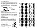
The 7080 has a fault output to tell you if the drive has overheated or if a short circuit
has occured at the motor outputs. The fault output is optically isolated for noise
immunity. This makes it more flexible and more reliable, but also harder to hook
up. To connect to 5 volt logic, follow the sketch below. For other connections,
consult the factory.
The photo transistor turns on when there is a fault. In circuit below, the signal will
be high (near 5 volts) when there is no fault. The signal will go low (0 volts) if a
fault occurs.
FAULT+
1k
1.2
TTL or CMOS input
FAULT–
AMPS/
PHASE
Setting Phase Current
Before you turn on the power supply the first time, you need to set the driver for the
proper motor phase current. The rated current is usually printed on the motor label.
The current you set on the 7080 is the peak current, not RMS.
The 7080 drive current is easy to set. If you wish, you can learn a simple formula
for setting current and never need the current table again. Or you can skip to the
table on the next page, find the current setting you want, and set the DIP switches
according to the picture.
Current Setting Formula
Locate the bank of tiny switches near the motor connector. Five of the switches
have a value of current printed next to them, such as 0.4 and 1.6. Each switch
controls the amount of current, in amperes (A), that its label indicates. There is
always a base of current of 0.8A. To add to that, slide the appropriate switches
toward their labels. You may need your small screwdriver for this.
1.4
AMPS/
PHASE
1.6
AMPS/
PHASE
1.8
AMPS/
PHASE
2.0
CURRENT
BASE = 0.8
-8-
3.2
1 2 3 4 5 6 7
SELF TEST
Example
50% IDLE
Suppose you want to set the driver for 5 amps
0.2
per phase. You need the 0.8 A base
current plus another 0.2, 0.8 and 3.2 A.
0.4
5.0 = 0.2 + 0.8 + 3.2 + 0.8 (base)
0.8
Slide the 0.2, 0.8 and 3.2 A switches toward the labels
1.6
as shown in the figure.
AMPS/
PHASE
2.2
AMPS/
PHASE
2.8
AMPS/
PHASE
3.0
AMPS/
PHASE
3.2
AMPS/
PHASE
3.4
AMPS/
PHASE
3.6
AMPS/
PHASE
3.8
AMPS/
PHASE
4.4
AMPS/
PHASE
4.6
AMPS/
PHASE
4.8
AMPS/
PHASE
5.0
AMPS/
PHASE
5.2
AMPS/
PHASE
5.4
AMPS/
PHASE
-9-
6.0
AMPS/
PHASE
6.2
AMPS/
PHASE
6.4
AMPS/
PHASE
6.6
AMPS/
PHASE
6.8
AMPS/
PHASE
7.0
AMPS/
PHASE