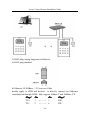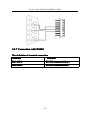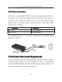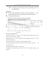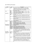
1
Access Control Station
Installation Guide
About this Guide
�
The Access Control Station User guide is designed to provide information to
install Access Control Station, for operation and configuration, please refer to the
corresponding user’s manual.
�
Not all function these guides introduce available in combination, all
is option.
�
About your machine function, please consult our company technical
personnel or the sales personnel .
Information in this document is subject to change without notice.
Access Control Station Installation Guide
Contents
1 Before Installing ..................................................................................... 1
1.1 Notice about installing ................................................................ 1
2 System Configuration ............................................................................ 4
2.1 The illustration of system construction ....................................... 4
2.2 The sketch map of communication ............................................. 5
3.Installation.............................................................................................. 6
3.1 Fixing mounting plate ................................................................. 6
3.2 Connect with peripheral equipment ............................................ 7
3.2.1 Door Sensor...................................................................... 9
3.2.2 Release Button ................................................................. 9
3.2.3 Alarm................................................................................ 9
3.2.4 Conntion with lock......................................................... 10
3.2.5 Ethernet connection........................................................ 15
3.2.6 Connection with RS232................................................. 17
3.2.7 Connection with RS485................................................. 18
3.2.8 Wiegand output.............................................................. 20
3.2.9 Power connection ........................................................... 21
3.2.10 Connect with external Weigend reader........................ 21
3.3 Fixing Access Control Station ................................................... 22
4. Fastening Access Control Station........................................................ 23
5. Others.................................................................................................. 24
5.1 Reset.......................................................................................... 24
5.2 Anti-dismantle button................................................................ 24
5.3 Cable doorbell........................................................................... 25
KR Series rechargeable battery specifications ........................................ 26
Access Control Station Installation Guide
1 Before Installing
1.1 Notice about installing
Access Control Station is a mass-produced product. It strictly tested
comply with the standard of China, U.S.A, and EU. This file contains
important information. It is better for you to read it carefully prior to use.
If you ignore it, the incorrect installation may cause the unit damage.
Although we could do our best to offer you service, the neglect to the
file could cause unwanted cost for you.
1. Before installation, please make sure the power is cut off, because it is
very dangerous if the power is on. The short circuit of power cable may
cause the core parts damage.
2. All exposed part of connection wire end cannot be exceeded 5mm to
prevent the bared wire accidental connection which leads to machine
break down. And also suggest using different color cable to connect.
3. In the place where the static is strong or in winter, please connect the
grounding firstly, in order to prevent the instant mass static damage the
machine.
4. Connect power supply with device in the last for the wiring
connection. If you find any unusual thing occur, please firstly cut off the
power, then go to examine. Keep in mind: wiring operation under power
on will lead to machine sudden damage; we are not liable for damages
and trouble due to such operation.
-1-
Access Control Station Installation Guide
5. The height to mountdevice is about 1.4-1.5 meter
6. After installation, please take off protection film on the fingerprint sensor to
get best recognize result.
7. After installation finish, when go to test the exit-door button, please
keep a personal in the outside, because sometimes the accidental issue
can bring on you are not able to go outside.
8. Our equipment offer an automatically function, please after the installing
finish. Run the auto-test function to confirm the installation finish.
9.We recommend using above the 12V/3A direct-current supply for
access control device, electricity lock better to powered by 12VDC, and
no more than 1.5 A electric current At this time, the electric current of
supply should be above1A than lock power. If the parameter of lock
power surpasses this scope, please connect technical personnel. If the
power had not met above requests, it possibly causes to be unable
normally to drive the electricity lock, even damage the device.
10. Before device to be connected please read and always follow "Quick
connect Guide" closely. Because the wrong wiring will cause the core
block and sensor to burn out, insult in device to break down, at this
cause we will not liable for any damages and trouble.
11. If the space between power adapters and device is too long, please
do not use the twisted-pair or other type ferrules for the power wire.
When the power wire is choused, you should consider attenuation of
voltage, which has passed long distance transfer.
12. Please use specialized RS485 cable and the RS232/485 converter
with power to hookup the network, the bus structure apply to connect
-2-
Access Control Station Installation Guide
with each device. When a long cable is used to transfer signal, it is need
to connect a matching resistance to receiver, and its value is 120Ώ.
13. Other more details items; please see also the user manual, the
operating instructions and the appendix and so on.
-3-
Access Control Station Installation Guide
2 System Configuration
2.1 The illustration of system construction
-4-
Access Control Station Installation Guide
2.2 The sketch map of communication
Access Control Station directly connects with PC through RS232 or
TCP/IP
Access Control Station connects with PC through RS485 network
3 Access Control Station connects with PC through TCP/IP network.
-5-
Access Control Station Installation Guide
3.Installation
3.1 Fixing mounting plate
① Take out a Access Control Station , dismantle the screw between
machine body and mounting plate until it is out, see figure (1).
② Carefully take up the bottom of mounting plate, see figure (2), push it
up, see figure (3), then take away the mounting plate.
③ Determine the position of mounting plate on the wall. The Access
Control Station should be mounted on the external wall of the door
approximately 1400mm from the ground to the unit bottom. After the
position is determined, you could drill a hole (18mm*20mm) for cable
out, see below figure shadowed part.
④ Make the hole of mounting plate meet the drilled hole on the wall,
Use the screw to fix it on the wall, (for the details please see following
figure)
⑤ after installation, please make sure the mounting plate is reliable,
fasten, not loosed.
-6-
Access Control Station Installation Guide
3.2 Connect with peripheral equipment
Caution: Do not to connect peripheral equipment before the power
of the device is cut down, otherwise it is possible to damage the
device badly
badly.
Please follow instruction to connect peripheral equipment
① Door sensor connection(sensor, GND)
② Exit-button connection(Button GND)
③ Alarm connection(Alarm+, Alarm-)
④ Door lock connection(NC, COM, NO )
⑤ Ethernet connection( RJ45-1, RJ45-2, RJ45-3,RJ45-4)
⑥ RS232 connection(232RX, 232TX, GND )
⑦ RS485 connection(485A,485B )
⑧ Wiegand output connection(WD0,WD1,GND )
⑨ Cable Bell (Bell+, Bell-)
⑩ Power connection (GND, +12V)
Cable socket
-7-
Access Control Station Installation Guide
Alarm -
RJ45-1
Alarm +
RJ45-2
NC
RJ45-3
COM
RJ45-6
NO
Button
GND
Sensor
WD0
Bell+
WD1
Bell-
GND
232RX
GND
232 TX
+12V
GND
The definition of socket without Wiegand input
485 A
485 B
BEEP
GLED
RLED
WD1
WD0
GND
+12V
The definition of socket with Wiegand input
Jump
-8-
Access Control Station Installation Guide
3.2.1 Door Sensor
The door sensor is used to detect the door open-close status, Access
Control Station can monitor if the door has been unauthorized open
through the door sensor, at this time it can output a alarm signal,
moreover, Access Control Station can trigger prompt warning if after
surpassing a timed period, the door still open.
3.2.2 Release Button
The exit-button is installed for in-door operation. When the switch of the
button is close, the door will open. The distance is approximately
1400mm from ground to exit-button bottom. Make sure that the exitbutton position is to align correct, upright and the connection is accurate
and reliable. (Unused exposed end of cable should be cut off, and use
insulating tape to wrap it.) Pay attention to electromagnetic disturbance.
(For example: The light switch, the computer and so on)
3.2.3 Alarm
Access Control Station alarm output is a switch signal , it is able to
connect with simple alarm by serial circuit, it also apply to top grade
alarm and monitor system as a trigger signal( this machine alarm function
only support 12 VDC Warner)
-9-
Access Control Station Installation Guide
3.2.4 Conntion with lock
The way of installing door lock depends on the type of lock and local
condition. Internal resistor, which comes from long distance transfer,
should be taken into consideration when selecting the cable of electric
power. The door lock should be installed reliable and stable. Ensure the
wiring is correct. For the strike lock and electromagnetic lock, you
should pay attention to positive and negative terminal connection. The
unused bare end of wire should be cut off and use insulating tape to wrap
it. The delay time of strike lock is adjustable according to different
conditions.
Normally close (NC), under normal state the equipment keeps up closed,
if force the equipment open, the circuit cut off, brings out the state change.
Normally Open (NO), under normally state the circuit is cut off, if force
the equipment open, the circuit will be closed, and produce a state change.
-10-
Access Control Station Installation Guide
GND
Power Ground
Ground(GND
GND),Current loop ground
Sensor
GND )the input port of door
Input terminal of door sensor
sensor(Sensor
Sensor,GND
sensor accepts the signal which come from normally closed contact
to detect the door opening and closing state, when the door is in closed,
the contact keep in closed state, if the door is opened by someone , the
circuit break, thus bring out state change. If unauthorized user opens this
door or opening time is too long, the controller will send alarm
Button
Input terminal of release door button(Button
Button, GND
GND)The input port
of release door button accepts the signal which come from normally
opened contact to indicate that somebody want to go out, the input
equipment such as “ action detector”, “ press sensitivity floor board” or
exit-door button all serve as source to send signal,if nobody send out
request to want to go out, the input keep disconnection , if somebody
want to go out, they trigger release door button, the circuit is closed.
Produce state change, the controller responded to the request, unlock and
permit door serve as passage mode.
Note
Note: the process of performance to unlock door is control by relay,
when you install door lock, there are two thing you must think about, -safety and security , in other words, do you want which result that is if
lose control of this door, the door is still in safety—“lost control but
safety” or if lose control of this door, the door still is security--- “ lost
control but security”
“Lost control but safety
safety”” is that the power supply cut off (maybe the
power supply is cut or the controller lose control of itself, the door will be
open automatically, and permit everybody freely to pass in and out, the
door is not ability to be closed until the system power on, these type of
doors are installed in the protective area which ensure everybody is able
-11-
Access Control Station Installation Guide
to pass in and out. One representative application of “ lost control but
safety” is to use electromagnetism lock, under normal power supply, the
door is controlled by the controller, once the power supply break off, the
electromagnetism lock will lose magnetism and does not take effect, the
door become a passage mode
“Lost control but security
security”” is that the power supply cut off, the door
will be locked automatically, do not permit external personal to come in,
but permit internal personal go out, the door is not to be unlocked until
the system power supply is in gear. Make sure that the door of “lost
control but security” will be installed in the area, which needs to be
protected through fair and foul. One representative application of “ lost
control but security” is to use electrical lock, if the power supply break
off, the external personal is not able to open the door, but the internal
person can open the by manual operation.
In the following three cases, we recommend that fingerprint machine
and lock be powered separately.
1) The working voltage of the lock is DC12V, but the current difference
of the fingerprint machine and the lock doesn’t exceed 1A.
2) The lock voltage is not DC12V.
3) The distance between lock and fingerprint machine is too far.
1、NC lock connection(Access Control Station and lock power by one
adapter together , Jump 2,3 pin closed).
-12-
Access Control Station Installation Guide
Lock
2、NO lock connection (Access control Station and lock powered by one
adapter together , Jump 2.3 pin closed).
Lock
-13-
Access Control Station Installation Guide
3、the output relay signal by Access control station, NC lock connection
(Access Control Station and lock powered by independent
adapters
jump 1,2 closed)
Lock
Lock Power
4、 the output relay signal by Access control station, NO lock connection
( Access Control station and lock powered by independent adapte r
-14-
Access Control Station Installation Guide
Lock Power
Lock
3.2.5
Ethernet connection
1)Access Control Station connects with PC through cross cable
2)Access Control Station connects with PC through network and HUB to
create a local network
-15-
Access Control Station Installation Guide
3) RJ45 plug wiring diagrams for Ethernet
a) RJ45 plug standard
b) Ethernet 10/100Base—T Crossover Cable
mostly apply to HUB and Switch, or directly connect two Ethernet
terminals(not through HUB), fully support 10Base-T and 100Base-TX.
Plug1 Pin
Pin
Plug 2
TX+
1 <——> 3
RX+
TX2 <——> 6
RX-16-
Access Control Station Installation Guide
RX+
3 <——> 1
TX+
RX6 <——> 2
TXc) Ethernet 10/100Base-T Straight Thru Cable
Support 10Base-T and 100Base-TX,apply to connect with network card
and HUB(or network outlet), sometime it is called (whips)”
Wiring standard Pin
Color
Pin Wiring standard
TX+
1 <— white orange —> 1
TX+
TX2 <— Orange
—> 2
TXRX+
3 <— white green —> 3
RX+
4 <— Blue
—> 4
5 <— Blue white
—> 5
RX6 <— Green
—> 6
RX7 <— White brown —> 7
8 <— Brown
—> 8
3.2.6 Connection with RS232
The definition of PC connection with Access Control Station
PC Serial Port
Access Control Station serial port
Pin2-Rxd
Pin3-Txd
Pin5-Txd
Pin4-Txd
Pin5-Gnd
Pin6-Gnd
-17-
Access Control Station Installation Guide
3.2.7 Connection with RS485
The definition of terminal connection
Terminal
Function
Pin1-485A
RS-485 communication +
Pin2-485B
RS-485 communication -
-18-
Access Control Station Installation Guide
-19-
Access Control Station Installation Guide
3.2.8 Wiegand output
Access Control Station provide standard Wiegand 26 output, which can
be connected to most of access controllers, like the way of connecting
with a ID reader or password keyboard. The distance from the controller
to device cannot be more than 15 meter (if the signal must be transferred
much further or there is a strong interference around, please adopt a
Wiegand signal amplifier)
Mote
Mote: no matter the device is powered by access controller or not, the
ground ports of them have to be properly together to ensure the
Wiegand transfer reliable
Terminal
Function
Pin1-WD0
Output Wiegand data 0 signal
Pin2-WD1
Output Wiegand data 1 signal
Pin3-GND
Ground
-20-
Access Control Station Installation Guide
3.2.9 Power connection
This device is powered by 12VDC. Its current is approximately 50mA in
the ready work status and 400mA in the work status. The power is
conducted along with the terminal; you can use the 12V-4A-supply
adapter that is provided along with the device. The detail about
connection is as follow.
Terminal
Pin1- GND
Pin2- PWR
Function
Power negative
Power positive
The following figure is an example, which takes a provided power
adapter to connect
3.2.10 Connect with external Weigend reader
Access control device whit the Weigand input function is able to connect
with card reader, which is located in outdoor or indoor, control the door
by the controller together, the cable which between access controller and
external card reader is no more than 90 meter.
-21-
Access Control Station Installation Guide
3.3 Fixing Access Control Station
① Confirm all connection plugs correctly.
② Align back iron-plate of Access Control Station body to mounting
plate properly, and push it up, see figure1, then push device
backward, see figure 2.
③ Turn and tie up the screw bottom.
After finishing installation, make ensure the body of device is fixed
tightly.
②
①
-22-
Access Control Station Installation Guide
4. Fastening Access Control Station
After all system installation finished, make a test and examine prior to
power on, inspect whether the lock driver is OK or not, for more details,
please see “User Guide” and “Software Manual”
①the green LED begins to glitter after power up.
②enter menu-〉Option-〉 Auto-test.
③enter menu-〉User manage-〉User Enroll-〉Fingerprint Enroll,Enroll a
fingerprint, and use the fingerprint to test access control system and door
lock..
④if there is no any problem. Please delete this enrolled fingerprint.
-23-
Access Control Station Installation Guide
5. Others
5.1 Reset
Due to operation error or other accidence, which leads the machine not to
work, you can restart machine through reset key.
①take a small tool which diameter is no more than 2mm.
②find reset mark of “res” on the left small hole on the bottom of device,
see following figure.
③Use the tool plug into the hole refer to the picture on right, then plug
out. The machine is able to restart.
Reset key
5.2 Anti-dismantle button
Anti-dismantle button is on middle of device, whose function is realized
by back-cover pressing the anti-dismantle button. When the device is
being dismantled, it will send an alarm signal through the terminal.
-24-
Access Control Station Installation Guide
5.3 Cable doorbell
There is a key which is remark as
is used for doorbell.
ic on(
) on the keypad , this key
Door Bell
Put the doorbell in the proper place, press the doorbell key on the device,
please see circle marked, after the doorbell receive a signal, it will ring.
Note : Because the terminal and key our provided is used for cable
doorbell, must join the power into the electric round.
-25-
Access Control Station Installation Guide
KR Series rechargeable battery specifications
specifications
� Model: MS621F
� Nominal voltage (V): 3
� Charging voltage (standard charge voltage): 2.8V-3.3V
(3.1V)
� Nominal capacity (mAh): 5.5
� Internal resistance (): 80
� Standard charge and discharge current (mA): 0.025
� The largest discharge current (continuous) (mA): 0.25
� Life cycle (times): 100% charge and discharge: 200; 20%
charge and discharge: 1000
� Size (mm): diameter: 6.8; Height: 2.1
� Weight (g): 0.23
Features
� Discharge capacity
� 3.3 V-2.0V with the high voltage at the same time, you will
receive a large discharge capacity. Charge and discharge
cycles longυ life
� Under the 3.3 V-2.0V the charge and discharge conditions
(discharge depth of 100%), can achieve more than 200
rounds of the charge and discharge.
� Excellence in the discharge
� A discharge to 0.0 V so far, can also show a stable
discharge capacity.
-26-
Access Control Station Installation Guide
�
UL (Underwriters Laboratories Inc) specifications (UL File
No.MH 15628)
Application
� Mobile, office equipment, and other electronic equipment, sever
as the standby power for clock functions of kinds of memory.
� dischargeν characteristics
Charge: Max 0.1 mA/96 hours
(rated current, rated voltage
charging)
Discharge: 25 μ A / cov = 2.0V
(rated current discharge)
Discharge characteristics
Proposed rated voltage.
Because of the charge current restrictions, the need to
connect to the current limit resistance
Nominal capacity: 3.3 V-2.0V, / FS products in the discharge capacity of 3.1 V-2.0V
within the typical scope
Internal resistance by the exchange value of Alternating Current
The largest discharge current: the available capacity of about 50 percent , the
current capacity of
Maintain the minimum capacity of 50 percent。
The number of repeated charge 100% and 20% of the nominal capacity as the
standard
-27-
Information in this document is subject to change without notice
Printed in China