1
CHIMU Micro AHRS User Manual
CHIMU User Manual Rev G.
Table of Contents
Contents
1.
Introduction ................................................................................................................................ 5
1.1
Limitations .......................................................................................................................... 5
1.1.1
Rate limits ..................................................................................................................... 5
1.1.2
Acceleration limits ......................................................................................................... 5
1.1.3
Magnetic field limits....................................................................................................... 5
1.1.4
BIT and User Responsibility .......................................................................................... 5
1.2
Theory of Operation ............................................................................................................ 6
1.2.1
Startup Conditions ........................................................................................................ 6
1.2.2
Dynamic Operation – Centripetal Acceleration .............................................................. 7
1.3
Modes of Operation ............................................................................................................ 7
2. Specifications and Characteristics .............................................................................................. 8
2.1
Performance Specifications ................................................................................................ 8
2.2
Electrical Characteristics .................................................................................................... 9
2.3
Absolute Maximum Ratings ................................................................................................ 9
2.4
Mechanical and Pin Assignments ..................................................................................... 10
2.4.1
Dimensions ................................................................................................................. 10
2.4.2
Recommended Connectors ........................................................................................ 10
2.4.3
Coordinate System and Orientation ............................................................................ 11
2.4.4
Pin Assignments ......................................................................................................... 12
3. Hardware Integration ................................................................................................................ 14
3.1
Power ............................................................................................................................... 14
3.1.1
Input Power ................................................................................................................ 14
3.1.2
Output Power .............................................................................................................. 14
3.2
Special Interface Pins ....................................................................................................... 14
3.2.1
External Speed Select – Pin 3 – DIO_1 ...................................................................... 14
3.2.2
Com Select – Pin 4 – SSEL ........................................................................................ 14
3.2.3
Special – Pin 11 – ISP ................................................................................................ 15
3.2.4
Speed Indicator – Pin 18 – ANA1................................................................................ 15
3.3
Communication................................................................................................................. 15
3.3.1
UART .......................................................................................................................... 15
3.3.2
SPI Bus....................................................................................................................... 15
3.4
Feedback LED .................................................................................................................. 15
4. Software Interface .................................................................................................................... 16
4.1
Basic Message Structure .................................................................................................. 16
4.1.1
Message format .......................................................................................................... 16
4.1.2
Number Formats ......................................................................................................... 16
4.1.3
CRC Checksum Code................................................................................................. 17
5. Input Message Details .............................................................................................................. 18
5.1
Input Message – Device ID IS Required! .......................................................................... 18
5.2
Input Message Summary .................................................................................................. 18
5.2.1
PING (ID 0x00) ........................................................................................................... 19
5.2.2
BIAS AND SCALEFACTOR (ID 0x01) ........................................................................ 20
5.2.3
DAC MODE (ID 0x02) ................................................................................................. 21
Note that in CHIMU –J and later versions, there are no native DAC voltage outputs. A separate
I2C device must be used to create voltage outputs. ................................................................. 21
5.2.4
ACCELEROMETER CALIBRATION MODE (ID 0x03) ................................................ 22
5.2.5
MAGNETOMETER CALIBRATION MODE (ID 0x04) .................................................. 23
5.2.6
TEMPERATURE CALIBRATION MODE (ID 0x05) ..................................................... 24
5.2.7
CONFIGURATION CLEAR (ID 0x06).......................................................................... 25
CHIMU User Manual Rev G.
5.2.8
CONFIGURATION SET (ID 0x07) .............................................................................. 26
5.2.9
GYRO BIAS SAVE (ID 0x08) ...................................................................................... 27
5.2.10 ESTIMATOR TYPE SET (ID 0x09) ............................................................................. 28
5.2.11 GYRO SCALE FACTOR CHECK (ID 0x0A) ................................................................ 29
5.2.12 CENTRIPETAL VELOCITY INPUT (ID 0x0B) ............................................................. 30
5.2.13 GYRO INITIALIZATION (ID 0x0C) .............................................................................. 31
5.2.14 DEVICE ID (ID 0x0D).................................................................................................. 32
5.2.15 MAGNETIC REFERENCE VECTOR (ID 0x0E) .......................................................... 33
5.2.16 SOFTWARE RESET (ID 0x0F) ................................................................................... 35
5.2.17 UART SETTINGS (ID 0x10)........................................................................................ 36
5.2.18 RESERVED (ID 0x11) ................................................................................................ 38
5.2.19 USER PIN OPTION SET (ID 0x12) ............................................................................. 39
5.2.20 GPS / Substituted Heading Replacement (ID 0x13) .................................................... 40
5.2.21 Advanced Magnetometer Calibration (ID 0x14) ........................................................... 41
5.2.22 Reserved Messages 0x15 and 0x16 ........................................................................... 42
5.2.23 User Orientation Definition (ID 0x17) .......................................................................... 43
6. Output Message Details ........................................................................................................... 44
6.1
Fixed Message Output...................................................................................................... 44
6.2
Output Messages ............................................................................................................. 44
6.2.1
PING (ID 0) ................................................................................................................. 46
6.2.2
IMU RAW (ID 1) .......................................................................................................... 47
6.2.3
IMU FP (ID 2).............................................................................................................. 48
6.2.4
Attitude (ID 3).............................................................................................................. 49
6.2.5
Bias and Scale Factor (ID 4) ....................................................................................... 52
6.2.6
Mode / BIT (ID 5) ........................................................................................................ 53
6.2.7
MAG CAL (ID 6).......................................................................................................... 54
6.2.8
GYRO BIASES (ID 7) ................................................................................................. 55
6.2.9
TEMPERATURE CALIBRATON DATA (ID 8) ............................................................. 56
6.2.10 DAC OFFSET READ (ID 9) ........................................................................................ 57
6.2.11 USER PIN OPTIONS READ (ID 10) ........................................................................... 58
6.2.12 MAGNETIC REFERENCE VECTOR (ID 14)............................................................... 59
6.2.13 RATE SENSOR SF CHECK (ID 15) ........................................................................... 60
6.2.14 RESERVED (ID 16) .................................................................................................... 61
6.2.15 USER ORIENTATION (ID 17)..................................................................................... 62
7. Software Reprogramming......................................................................................................... 63
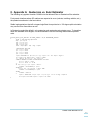
8. Appendix A: Quaternion vs. Euler Estimator ............................................................................ 64
9. Appendix B: Temperature Calibration ...................................................................................... 65
10.
Appendix C: Set Point Calibration ........................................................................................ 66
11.
Appendix D: Accelerometer Calibration ............................................................................... 67
12.
Appendix E: Magnetometer Calibration ............................................................................... 68
12.1 Basic Calibration – Hard Iron calibration ........................................................................... 68
12.2 Advanced Calibration – Hard and Soft Iron Calibration ..................................................... 69
12.3 Advanced Calibration – Hard and Soft Iron Calibration with fine correction ....................... 70
CHIMU User Manual Rev G.
Release Notes
Title
Subtitle
Type
Document number
Revision Index
Initial Release
A
B
CHIMU
CHIMU User Manual
Manual
UM1000
Date
6/2009
9/2009
10/2009
Name
MR
MR
MR
C
12/9/09
MR
D
12/28/09
MR
D2
3/4/10
MR
D3
3/8/10
MR
E
4/20/11
MR
F
12/27/11
MR
G
10/26/15
MR
Status / Comments
Initial release
Updates to DAC offsets, message structure
Updated temperature and bias calibration / save
appendices.
Updated CRC information (start value added)
Updated mechanical drawing to show space
between pin rows
SW Version 1.4 additions include:
Temperature calibration made more robust
Euler angles are now output at 20 Hz update
rate even if quaternion estimator is selected
Added user pin select message input (0x12)
and output (0x0A)
Added substitute (GPS) heading use
message (0x13) to replace magnetometer
corrections in high magnetic environments
Noted: Yaw angle reported is True North if
magnetic reference vector has been applied,
else magnetic north is reported
General text cleanup
Output Message 2, floating point data, had incorrect
sequence of values. Previous manual showed accel,
mags, then rate. Actual software has always been
accel, rate, mags. Documentation updated only.
Pin 17 and 18 were incorrectly swapped in the
documentation.
Pin 17 was incorrectly called out as the analog input.
Pin 18 is the analog input pin for speed if using that for
centripetal calculations (vs. software messages). Fixed
in this revision (documentation change only)
Revision for CHIMU –J (Josephine) module.
Significant changes to messages, endianess, sensor
capability
Reported software version will be 2.0 or
higher
Secondary connector description added
Euler filter no longer an option
DAC output no longer a feature (contact us
for instructions on how this can be
accomplished however)
Temperature calibration of rate sensors now
standard in basic module
Acceleration and Magnetometer calibration
procedures included in Appendices
New serial boot loader reprogramming
feature
Corrections to manual
100 Hz UART output now supported if
messages are reduced (no raw, no bias)
Correction to secondary connector
(MISO/MOSI lines were incorrect)
Added advanced magnetic calibration for software 2.10
and above. Added user orientation message 0x17.
CHIMU User Manual Rev G.
IMPORTANT DISCLAIMERS
This document and the use of any information contained therein, is subject to the acceptance of the Ryan Mechatronics terms and
conditions. They can be downloaded from www.ryanmechatronics.com.
Ryan Mechatronics LLC makes no warranties based on the accuracy or completeness of the contents of this document and reserves the
right to make changes to specifications and product descriptions at any time without notice.
Ryan Mechatronics LLC assumes no liability for damages or otherwise due to use of the information in this document or application of any
device described in this document.
Ryan Mechatronics LLC stresses end user compliance with all applicable laws and regulations when using devices of this nature. Use by
an end user in violation of any applicable laws is automatic basis for termination of warranty, technical support and future sales.
Ryan Mechatronics LLC reserves all rights to this document and the information contained herein. Reproduction, use or disclosure to third
parties without express permission is strictly prohibited.
Copyright © 2009 – 2015, Ryan Mechatronics LLC
CHIMU User Manual Rev G.
1. Introduction
The CHIMU is a miniature, low cost Attitude Heading Reference System (AHRS). AHRS units
employ rate, acceleration, and magnetic sensing to provide a full inertial attitude and heading
estimate, even under stationary conditions. The CHIMU is intended for use in motion sensing
applications including, but not limited to:
UAVs (AUVs, UAS, etc)
Robotics
Sports training and analysis
Education
Rocket science
1.1 Limitations
The unit, like any IMU / AHRS, can be pushed beyond the limits of its ability to sense any of the
measurements it needs to operate correctly. The following list includes results that are known to
occur if operation exceeds the limits listed later in this document.
1.1.1 Rate limits
Saturation of maximum rate in any axis for any amount of time will result in an incorrect attitude
estimate. The longer the saturation duration, the more error will be present in the attitude
determination. The attitude estimate shall recover once saturation has stopped and the internal filter
has time to reconverge on the correct solution.
1.1.2 Acceleration limits
Excessive acceleration can include acceleration above the rated levels in continuous application
(static / low frequency g’s), more elusive vibration (sinusoidal / random) or shock (impulse / random)
events that may not show full saturation of the accelerometers in data output, but have affected the
sensors internally and corrupted the values. Continued acceleration above the limits or excessive
vibration / shock events can corrupt the computation of rate sensor biases, leading to poor bias
estimates and a corrupt attitude estimate.
1.1.3 Magnetic field limits
Saturation of the local magnetic field can result in a pervasive attitude estimate error as well.
Calibration of the unit in the final configuration will help prevent errors introduced by hard iron in the
local area. However, induced magnetic fields from high current devices or high power RF circuitry
can result in operational errors. After a proper calibration, no axis should exceed a +/- 1 value.
1.1.4 BIT and User Responsibility
Automatic sensing of limits being exceeded is difficult. However, the CHIMU does have some
internal capability to discern these conditions. Magnetic sensor saturation is reported in the Built In
Test (BIT) message. Future software revisions may include an indication of saturation or other
errors on other sensors. No system is fool proof however, and all correct use and planning for
events in case of failure are the responsibility of the user.
CHIMU User Manual Rev G.
5
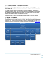
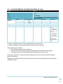
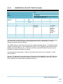
1.2 Theory of Operation
The CHIMU is an integrated set of MEMS sensors that are managed via an onboard CPU to provide
attitude and heading information, along with raw sensor data and other useful information. A top
level flow of the primary components are shown in this figure:
Rate
Acceleration
Magnetic flux
CPU
•3 axis rate
measurements
•Two sensor
combination for all
axes on planar
baord
•Measure angular
rotation
•3 axis
accelerometer
•Measures linear
acceleration forces
•3 axis
magnetometer
•Scalable for
sensitivity
(application
specific)
•Measureas earth
magnetic field (and
surrounding
environment)
•Handles sensor
reads
•200 Hz quaternion
attitude estimator
•Centripetal
corrections
•Temperature
calibration
Output / User
Interface
•Attitude, heading,
raw sensor data
output
•UART
•SPI - 200Hz
1.2.1 Startup Conditions
The most difficult operation for a MEMS based IMU to perform occurs at turn on. In order to provide
a fast, reliable estimate of attitude, some systems require the unit to be held motionless during turn
on. This is to provide a “zero” for immediate calibration.
The CHIMU-J does not require this turn on requirement. Static calibration values across the
operating temperature range are preprogrammed prior to delivery (or are calibrated / recalibrated
after delivery if necessary). In-run biases for the unit sensors are calculated as part of the internal
processing after turn on, and compensate for minor changes that may have occurred over time from
factory defaults and operational conditions.
CHIMU User Manual Rev G.
6
1.2.2 Dynamic Operation – Centripetal Acceleration
Operation of an IMU in a dynamic platform like an airplane can lead to incorrect attitude
computations unless centripetal accelerations are accounted for. Many low cost MEMs based IMUs
do not address this.
The CHIMU allows two methods for compensation of centripetal accelerations. Both require an
external input of vehicle velocity. The first, and most useful for many applications, is an external pin
that allows input of forward speed as an analog voltage. The second requires a full 3 axis velocity
message to be provided to the unit via the serial port or SPI port.
External computation of velocity can be provided by airspeed sensors or a GPS unit (typically).
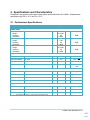
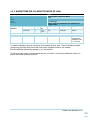
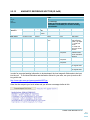
1.3 Modes of Operation
The CHIMU has been designed to be simple and effective at providing attitude and heading
information with minimal or no user intervention. However, there are some modes for calibration that
likely will be used. Below is a top level description of the typical operating modes for the unit. This
diagram may be useful in understanding the software commands to the module found in this section.
INIT Mode
-Flash load
-Start Bit
-Hardware config
RUN
Mode
Accelerometer Calibration Mode
Magnetometer
Calibration
Mode
Temp
Calibration
Mode
Position unit
3 axis
revolution,
constant
update
Rate sensors
Background
BIT
X
up/down
Y
up/down
Flash Ops:
Settings
Change and
Commit
Z
up/down
CHIMU User Manual Rev G.
7
2. Specifications and Characteristics
Presented in this section are the sensor and system specifications for the CHIMU. All parameters
specified are @ VDD = 3.0 V and Ta = 25°C.
2.1 Performance Specifications
Characteristics
Conditions
Min
Attitude and Heading
(steady state)
Roll
Range
Accuracy
Resolution
Pitch
Range
Accuracy
Resolution
Yaw
Range
Accuracy
Resolution
Angular Rate
Typical
Units
0 to 360
0.5
0.0004
°
° RMS
°
+/-90
0.5
0.0004
°
° RMS
°
0 to 360
0.5
0.0004
°
° RMS
°
° / sec
Range
All axes
±2000
Rate noise density
All axes
0.03
Bandwidth
All axes
Resolution
All axes
10
Max
188
° /sec /
256
Hz
<±0.07
° / sec
Acceleration
±8
g
292
780
Hz
<±1
<±2
<±4
mg
±1.3
±1.3
±8.1
Gauss
Range
All axes
±2
±4
Noise density
All axes
Bandwidth
All axes
37
Resolution
All axes
Range
All axes
Bandwidth
All axes
10,000
Resolution
All axes
7
218
Magnetic Flux
milligauss
Specifications are subject to change at any time without notice
CHIMU User Manual Rev G.
8
2.2 Electrical Characteristics
Characteristics
Conditions
Min
Typical
Max
Units
3.1
3.3
6.5
V
30
33
36
mA
Power
Supply Voltage
Range
Current
Vdd
Referenced to GND
Average, measured at 3.3V
Time
Time to first valid
data
Bias settling time
Power on to first message out
0.1
sec
Static test step change condition
<10
sec
Specifications are subject to change at any time without notice
2.3 Absolute Maximum Ratings
Parameter
Rating
Acceleration (any axis, 0.5 ms)
Unpowered
Vdd
2000g
Output Short-Circuit Duration
(Any Pin to Common)
Operating Temperature Range
TBD
Storage Temperature Range
-40°C to +125°C
-0.3V to +7V
-30°C to +85°C
Specifications are subject to change at any time without notice
Stresses above those listed under the Absolute Maximum Ratings may cause permanent damage to
the device. This is a stress rating only; functional operation of the device at or near these or any
other conditions above those indicated in the operational section of this specification is not implied.
Exposure to absolute maximum rating conditions for extended periods of time may affect device
reliability.
Drops onto hard surfaces can cause shocks of greater than 2000 g and can exceed the absolute
maximum rating of the device. Exercise care during handling to avoid damage.
CHIMU User Manual Rev G.
9
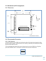
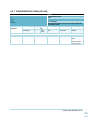
2.4 Mechanical and Pin Assignments
2.4.1 Dimensions
0.9”
0.8”
PIN 12
0.11”
X
Y
Z (out)
0.72”
X1 (alternate connector)
0.05”
PIN 1
PIN 1
PIN
24
0.11 x
2
1”
All units shown in inches
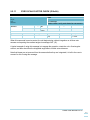
2.4.2 Recommended Connectors
2.4.2.1 Main Connector
The main connectors on the CHIMU are located on the sides of the board and are intended to allow
plug into a board or socket. These pins have a 0.05” spacing. Specifically, the CHIMU pins are DigiKey part number S9014E-12-ND.
The recommended mate (socket) that custom designs should use to plug CHIMU into is Digi-Key
part number S9005E-12-ND. For reference, a picture of this connector is shown here:
CHIMU User Manual Rev G.
10
2.4.2.2 Secondary Connector (X1)
The secondary connector is located on the top of the CHIMU and has a limited set of connections for
power and communication. This connector is an 8 pin Molex socket. The mating connector for this
is Digi-Key part number WM1726-ND, but this is just the connector housing. Pre-crimped wires can
be found at Newark, part number 06-66-0013. For reference, a picture of this connector is shown
here:
2.4.3 Coordinate System and Orientation
Orientation shown (X/Y/Z) frame is the local body frame, using standard aircraft axes. The unit with
applied axes coordinate frame is shown below.
It is assumed for the rest of this manual that this axis corresponds to a standard vehicle axis. All
rotations obey the “right hand rule”. In this case, the following terms are defined:
Pitch rate / angle ( , θ) – positive pitch rate is rotation about the Y axis from the Z towards
the X axis.
Roll rate / angle ( , Φ) – positive roll rate is rotation about the X axis from the Y to the Z axis.
Yaw rate / angle ( , Ψ) – positive rate is rotation in a clockwise direction about the Z axis
from the X to the Y axis.
CHIMU User Manual Rev G.
11
2.4.4 Pin Assignments
Table 1 – Main Connector Pin Assignments
Pin #
Pin Name
I/O
1
Vin
N/A
Pin
Connection
Required
for Typical
Operation?
X
2
GND
N/A
X
3
DIO_1
4
NSS
I
External Speed Sensor enable
(ground pin if external analog speed sensor available)
COM Select
5
MOSI
O
SPI – Master Out Slave In
6
SENSOR RX
I
7
SENSOR TX
O
8
MISO
I
UART com TO CHIMU
3.3V level
UART com FROM CHIMU
3.3V level
SPI – Master In Slave Out
9
SCK
O
SPI – Clock
10
GND
N/A
11
ISP
I
12
SWCLK
I
13
NC
N/A
14
SCL
O
Internal I2C Clock – Do Not Connect
15
SDA
O
Internal I2C Data – Do Not Connect
16
GND
N/A
17
ANA2
I
Reserved for future use
18
ANA1
I
X axis velocity input
Enabled by Pin 3
19
GND
N/A
20
DIO_2
21
GND
22
SWDIO
23
RESET
I
Special – Programming use, do not connect in typical
application
Soft reset – active low reset holds CPU in reset
24
3.0V Out
O
Limited 3.0V supply (50mA max)
I
X
I
Input power
X
Special – Hold low for boot loader operation in event of
software reprogram. Do not connect in typical
application
Special – Programming use, do not connect in typical
application
No function
X
X
I
N/A
Description
Reserved for future use
X
CHIMU User Manual Rev G.
12
Table 2 – Secondary (X1) Pin Assignments
Pin #
Pin Name
I/O
1
Vin
N/A
Pin
Connection
Required
for Typical
Operation?
X
2
GND
N/A
X
3
SENSOR RX
I
4
SENSOR TX
O
5
SSEL
I
UART com TO CHIMU
3.3V level
UART com FROM CHIMU
3.3V level
Slave select
6
MISO
I
SPI – Master In Slave Out
7
MOSI
I
SPI – Master Out Slave In
8
RESET (OR)
SCK
O
Hardware dependent.
Basic: This pin is the soft reset
SPI: SPI – Clock
X
Description
Input power
Note: Hardware type selected when purchased
CHIMU User Manual Rev G.
13
3. Hardware Integration
Presented in this section are selected hardware interface comments to help ease integration of the
unit in the end user system.
3.1 Power
3.1.1 Input Power
The CHIMU module operates off a nominal 3.3V input. However, up to 6.5V may be applied. A
higher voltage may result in more thermal dissipation on the board, but this should not affect
operation. Do not exceed 6.5V or damage may result.
The system draws very little power; typically it will require 30 mA of supply for operation. More will
be required if the output power pin is used.
If the 3.0V output pin is used to power external devices, then the input power current will need to be
increased to support this additional use.
3.1.2 Output Power
The module outputs 3.0V from its onboard regulator on pin 24. This is not intended to be used to
drive any high current or critical loads, but may be useful for pull up / down or LED operation. Total
current from this output should be limited to less than 50mA. More than this risks interfering with
operation of the unit.
3.2 Special Interface Pins
The CHIMU utilizes external pins to help configure the unit if software interfacing is not possible.
These pins are described here.
3.2.1 External Speed Select – Pin 3 – DIO_1
Pin 3 indicates to the unit that the external voltage on Pin 18 (ANA1) should be treated as the
forward (X) velocity indicator.
High / not connected
o No external hardware speed input
o DO NOT EXCEED 3.0 VOLTS ON THIS PIN
Low / Grounded
o Pin 18 (ANA1) acts as a direct indicator of forward (+X) velocity according to the bias
and scale factor associated with this input
o Scale ranges from 0 to 3.0V
o Standard bias and scale factor result in a linear scale of:
0 V = 0 m/s
3.0V = 66 m/s (147 mph)
3.2.2 Com Select – Pin 4 – SSEL
Pin 4 indicates to the unit which communication structure should be used. Currently, SPI
communication is only as a master device. This pin is reserved for future use in an SPI slave
configuration.
CHIMU User Manual Rev G.
14
3.2.3 Special – Pin 11 – ISP
This pin, when held low, will force the on board CPU into a boot loader mode for accepting software
uploads via serial port. In a normal application, leave unconnected. DO NOT DRIVE HIGH!
3.2.4 Speed Indicator – Pin 18 – ANA1
Described previously, this pin (when enabled by Pin 3) will accept a voltage in the range of 0 to 2.5V
to represent a forward speed of 0 to 66 m/s to allow centripetal corrections.
This pin may be interfaced (with proper scaling) directly to a pitot tube airspeed sensor output for
example.
If more complex velocities are present, or if a hardware interface is not desired, then software input
of the vehicle velocity should be used. For aircraft, a forward speed indicator should be sufficient for
most applications.
3.3 Communication
The CHIMU has two means of communication – a standard UART and an SPI port.
3.3.1 UART
The UART is a 3.3V level interface. The unit does not use hardware handshaking. It is always 8
bits, no parity, and one stop bit (8-N-1). Do NOT interface with a standard RS-232 port, as the
voltages on that port will damage the unit. An external adapter that uses 3.3V to convert to RS-232
levels can be powered from the onboard 3.3V regulator.
Standard operation is at 115k baud with a message output rate of 25Hz. Currently, this is a fixed
baud rate. However, the data output rate can be varied from 0 to 50Hz and a message mask allows
selective output of data.
3.3.2 SPI Bus
The SPI bus is configured as a master device. The SPI bus outputs all data at the full 200Hz data
rate. Further details, including C source code for interfacing to this bus and receiving data, is
available upon request from customers.
3.4 Feedback LED
There is one (1) informational LED on the unit. This LED is for information only, and is not
necessary to view during operation. The LED operation is as follows:
Boot / Initialize – Solid on
Normal operation – toggling of on/off at ½ the UART interface output rate
Failed operation in use – Solid on or solid off
CHIMU User Manual Rev G.
15
4. Software Interface
The CHIMU hardware com interfaces have been described already. Details on software setup and
communication are presented here.
4.1 Basic Message Structure
Input and Output messages from the unit are identical. Both include header and checksum and
other information to protect data integrity and allow easier decoding by the end user.
4.1.1 Message format
Both input and output messages have a defined structure that consists of the following:
(2) header bytes (0xAE 0xAE)
(1) Message length byte – one byte representing the payload length only (i.e. no header,
length, device id, message id or checksum included)
(1) Device ID byte (useful when multiple units are used in a single application)
(1) Message ID byte
(xxx) Data bytes (varies with message)
(1) Checksum byte
The checksum byte is the LSB of a 32 bit CRC checksum calculated for the entire message,
including header bytes, length, id, and data bytes. Details and code for calculating this checksum
are provided later in this section.
4.1.2 Number Formats
Much of the data messages use single bytes and unsigned integers, which are typically easy to
understand. A number format list is presented here for clarity on number formats however.
UNLIKE prior CHIMU and CHIMU 2010 units which used a Big Endian output format, the
CHIMU –J units are Little Endian. This is a significant difference for legacy applications.
NOTE: Most PC’s (Intel) are Little Endian oriented.
All floating point values are transmitted in IEEE754 single precision.
Table 3 – Number Formats
Abbreviation
Type
U1
I1
X1
U2
I2
X2
U4
L4
Unsigned char
Signed char
Bitfield
Unsigned short integer
Signed short integer
Bitfield
Unsigned long
Signed long
Size
(bytes)
1
1
1
2
2
2
4
4
R4
CH
IEEE 754 Single Precision
ASCII encoded
4
1
Comment
2’s complement
2’s complement
2’s complement
Min/Max
0 … 255
-128 … 127
n/a
0 … 65535
-32768 … 32767
n/a
0…4,294,967,295
-2,147,483,648 …
2,147,483,647
-1*2^127 … 2^127
CHIMU User Manual Rev G.
16
4.1.3 CRC Checksum Code
The checksum calculated for outgoing messages is a 32 bit CRC code. C code to compute the
entire checksum is shown below.
Important notes:
1) Only the LSB of this CRC is appended to output message
2) The starting polynomial is 0xFFFFFFFF
#define POLY 0xEDB88320 // bit-reversed version of the poly 0x04C11DB7
unsigned long UpdateCRC (unsigned long CRC_acc, unsigned char CRC_input)
{
unsigned char i; // loop counter
// Create the CRC “dividend” for polynomial arithmetic (binary arithmetic
// with no carries)
CRC_acc = CRC_acc ^ CRC_input;
// “Divide” the poly into the dividend using CRC XOR subtraction
// CRC_acc holds the “remainder” of each divide
//
// Only complete this division for 8 bits since input is 1 byte
for (i = 0; i < 8; i++)
{
// Check if the MSB is set (if MSB is 1, then the POLY can “divide”
// into the “dividend”)
if ((CRC_acc & 0x00000001) == 0x00000001)
{
// if so, shift the CRC value, and XOR “subtract” the poly
CRC_acc = CRC_acc >> 1;
CRC_acc ^= POLY;
}
else
{
// if not, just shift the CRC value
CRC_acc = CRC_acc >> 1;
}
}
// Return the final remainder (CRC value)
return CRC_acc;
}
CHIMU User Manual Rev G.
17
5. Input Message Details
Shown in this section are specific input message requirements and details
5.1 Input Message – Device ID IS Required!
The unit shall not respond to requests that do not contain its device ID. The default factory value for
the device ID is 0x01, but can be changed by the user. The broadcast device ID of 0xAA will
force any units listening to accept the messages sent.
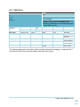
5.2 Input Message Summary
The output messages from the unit are shown in this summary table:
Table 4. CHIMU Message Input
Name
Ping
Bias and Scale Factor
DAC Mode
ID
0x00
0x01
0x02
Length
0
67
6
Accelerometer
Calibration
Magnetometer
Calibration
Temperature
Calibration
Configuration CLEAR
Configuration SET
Gyro Bias Save
0x03
1
Description
Communication check
Sets bias and scale factor values
Sets the DAC offsets for custom modules using
off board DAC generation of voltages.
Calibrates accelerometers
0x04
1
Calibrates magnetometers
0x05
1
Temperature calibration of rate sensors
0x06
0x07
0x08
1
2
1
Estimator Type
0x09
1
Gyro SF Check
0x0A
1
Centripetal Velocity
0x0B
13
Initialize Gyros
Device ID Change
Magnetic Reference
Vector
Reset
UART Rate and Mask
Settings
Reserved
User Pin Option Select
GPS / Substitute
Heading
Advanced
Magnetometer
Calibration
RESERVED
User Orientation
Definition
0x0C
0x0D
0x0E
0
2
21
0x0F
0x10
1
6
0x11
0x12
0x13
6
5
Clears configuration flash memory
Saves current configuration to flash memory
Saves current rate sensor biases as power up
defaults. This is in addition to temperature
calibration values for bias.
No effect (unused). Attitude estimator is always
quaternion based in CHIMU –J.
Special – integrates gyros only to check scale
factor
Allows input of vehicle velocity vector to account
for centripetal acceleration
Sets current value for rate sensors as zero point
Sets new device ID
Sets new magnetic reference vector and
declination / inclination for local area
Performs a software reset of the unit
Sets the output rate and message mask on the
UART.
Sets options enabled by Pin 20 use
Allows override of internal yaw reference source.
0x14
65
Allows set of soft iron / hard iron matrix/
offset/scale factor data. Overwrites any hard iron
(typical) calibration.
0x15, 0x16
0x17
16
Enters and saves flash memory a user rotation of
the output sensor data and attitude.
CHIMU User Manual Rev G.
18
5.2.1 PING (ID 0x00)
Name
PING
0x00
1
Input Message
Pings the unit. Unit responds with ping output
message, BIT message, and user requested
message. Useful for software protocol test.
Message
Description
ID
Length
Type
Comment
Message
Structure
Byte offset
0
Header
Length
0xAE 0xAE
1
Number format
U1
Scaling
-
Device
ID
id or
0xAA
ID
Package
Checksum
0x00
None
XSUM
Name
Requested
Message
Units
-
Description
Requests a
specific output
message
This message forces a ping output message (0x00) and a BIT message (0x05) as a response
regardless of the package data.
The message indicated by the package byte (other than 0x00 or 0x05) will be output as well.
CHIMU User Manual Rev G.
19
5.2.2 BIAS AND SCALEFACTOR (ID 0x01)
Name
BIAS AND SCALE FACTOR
0x01
67
Input Message
Changes bias / scale factor
Message
Description
ID
Length
Type
Comment
Message
Structure
Header
Length
0xAE 0xAE
67
Byte offset
0
Number format
U1
1
Device
ID
id or
0xAA
ID
Package
Checksum
0x01
See Below
XSUM
Scaling
-
Name
Read / Write
Units
-
I2
-
-
3,5,7
I2
-
Temp Sensor
Bias
Accel X, Y, Z bias
Description
Requests a read
or specifies a
write of data
Do not change
9,11,13
15, 17, 19
I2
I2
-
Rad/s
Local gauss
(normalized)
21
I2
-
23
27,31,35
R4
-
Rate Sensor bias
Magnetometer
bias
Hardware analog
1 read (velocity
input) bias
Temp Sensor SF
Accel X, Y, Z SF
39,43,47
51,55,59
R4
R4
-
Rate Sensor SF
Magnetometer SF
Rad/s
Local gauss
(normalized)
63
R4
-
Hardware analog
1 read (velocity
input) SF
m/s^2
m/s^2
Note: 3 integers,
one for each axis
“”
“”
Note: 3 floating
point values, one
for each axis
“”
“”
Scale as needed
for external
hardware speed
input.
Typically, these settings are not altered via this message. Calibration of the unit stores these values
automatically. However, advanced users may wish to save configurations and write them for
experimental reasons.
CHIMU User Manual Rev G.
20
5.2.3 DAC MODE (ID 0x02)
Name
DAC Mode
0x02
4
Input Message
Changes DAC output mode and allows offset
changes
Message
Description
ID
Length
Type
Comment
Message
Structure
Header
Length
0xAE 0xAE
6
Byte offset
0
Number format
U1
1
U1
Device
ID
id or
0xAA
ID
Package
Checksum
0x02
See Below
XSUM
Scaling
-
Name
Rate / Angle
Units
-
-
Read / write /
save
-
Description
No effect. Output
is in rate mode
always
0 = requests a
DAC offset
message
1 = writes the
offsets until the
next power cycle
2
U2
-
Offset channel 0
-
4
U2
-
Offset channel 1
-
2 = commits them
to flash memory
(i.e. permanent)
Counts for ADC
(0 to 4095) offset
to the Pitch
channel
Counts for ADC
(0 to 4095) offset
to the Roll
channel
Note that in CHIMU –J and later versions, there are no native DAC voltage outputs. A separate I2C
device must be used to create voltage outputs.
CHIMU User Manual Rev G.
21
5.2.4 ACCELEROMETER CALIBRATION MODE (ID 0x03)
Name
Accelerometer Calibration Mode / Selection
0x03
1
Input Message
Enters / designates unit orientation for calibration
of accelerometers
Message
Description
ID
Length
Type
Comment
Message
Structure
Byte offset
0
Header
Length
0xAE 0xAE
1
Number format
U1
Scaling
-
Device
ID
id or
0xAA
ID
Package
Checksum
0x03
See Below
XSUM
Name
Position
Units
-
Description
0 = level (x, y = 0;
z = -1)
1 = upside down
(x, y = 0; z = 1)
2 = up (x = 1, y, z
= 0)
3 = nose down (x
= -1, y, z =0)
4 = right wing up
(x = 0, y = +1, z =
0)
5 = right wing
down (x = 0, y=-1,
z =0)
To start the calibration process, the level (0) position must be sent first.
To finish the calibration, the right wing down (5) position must be sent last.
Recommended use if needed:
Enter calibration with unit level command
Progress thru all 5 remaining positions sending required command at each position
Final position results in bias and scale factor being saved to flash memory.
Any position other than 5 may be sent during calibration and the new value shall be recorded in
place of the last one.
Keep the unit motionless during the command to prevent erroneous acceleration from entering the
calibration process.
CHIMU User Manual Rev G.
22
5.2.5 MAGNETOMETER CALIBRATION MODE (ID 0x04)
Name
Magnetometer Calibration Mode
0x04
1
Input Message
Enters / exits unit orientation for calibration of
magnetometer
Message
Description
ID
Length
Type
Comment
Message
Structure
Byte offset
0
Header
Length
0xAE 0xAE
1
Number format
U1
Scaling
-
Device
ID
id or
0xAA
ID
Package
Checksum
0x04
See Below
XSUM
Name
Action
Units
-
Description
0 = Enter
magnetometer
calibration mode
1 = exit mode
To start the calibration process, the Enter (0) command must be sent. The unit should be rotated
continuously, pointing every axis at the north vector (magnetic north for you location).
Exit the calibration process by sending a (1) in the payload.
Do not have high current or ferrous metal near the unit (within 1 foot) during calibration unless it is
part of the normal operating condition.
CHIMU User Manual Rev G.
23
5.2.6 TEMPERATURE CALIBRATION MODE (ID 0x05)
Name
Temperature Calibration Mode
0x05
1
Input Message
Enters / exits temperature calibration of unit. Not
typically needed, done at factory.
Message
Description
ID
Length
Type
Comment
Message
Structure
Byte offset
0
Header
Length
0xAE 0xAE
1
Number format
U1
Scaling
-
Device
ID
id or
0xAA
ID
Package
Checksum
0x05
See Below
XSUM
Name
Action
Units
-
Description
0 = Enter temp
cal mode
1 = exit mode
OBSOLETE FOR CHIMU – J
To start the calibration process, the “Enter” (0) command must be sent. The unit should be kept
completely motionless at a cooled temperature initially, then allow the unit to slowly warm to a higher
temperature.
ID reserved for future use
At least 30 degrees of temperature change from start to finish should be experienced for best
results.
Results are saved to flash memory automatically at the exit of the mode.
Please see the appendix for more information.
CHIMU User Manual Rev G.
24
5.2.7 CONFIGURATION CLEAR (ID 0x06)
Name
Configuration Clear
0x06
1
Input Message
Clears all saved flash and returns unit to defaults
after power cycle
Message
Description
ID
Length
Type
Comment
Message
Structure
Byte offset
0
Header
Length
0xAE 0xAE
1
Number format
U1
Scaling
-
Device
ID
id or
0xAA
ID
Package
Checksum
0x06
See Below
XSUM
Name
Action
Units
-
Description
0xAB = clears
flash
All other values
have no effect
CHIMU User Manual Rev G.
25
5.2.8 CONFIGURATION SET (ID 0x07)
Configuration Set
0x07
1
Input Message
Sets current configuration with option to save it to
flash memory
Description
ID
Length
Type
Comment
Message
Structure
Byte offset
0
1
Header
Length
0xAE 0xAE
2
Number format
U1
Scaling
-
X1
Device
ID
id or
0xAA
-
ID
Package
Checksum
0x07
See Below
XSUM
Name
Action
Units
-
Description
0xAB = saves to
flash memory for
subsequent use.
Bit field settings
All other values
have no effect in
this field.
See bit settings
and meanings
below
-
This message allows certain configuration settings to be set and saved to flash if required. The
configuration settings can be set without saving to flash also to test the settings. Flash save will only
occur if 0xAB is written as the first byte in the payload.
The bits in the configuration status that can be altered directly in the second package byte are as
follows:
bit 7
Allow
Hardware
Pin Config
Override
(default = 1,
allow)
bit 6
X
bit 5
X
bit 4
X
bit 3
X
bit 2
Temperature
Calibration
Start / Stop
(default = 0,
do not use)
bit 1
Hardware
Centripetal
Velocity
Enable
(default = 1,
enabled)
bit 0
SPI Enable
Override
(default = 1,
enabled)
CHIMU User Manual Rev G.
26
5.2.9 GYRO BIAS SAVE (ID 0x08)
GYRO BIAS SAVE
0x08
1
Input Message
Saves rate sensor biases
Description
ID
Length
Type
Comment
Message
Structure
Byte offset
0
Header
Length
0xAE 0xAE
1
Number format
U1
Scaling
-
Device
ID
id or
0xAA
ID
Package
Checksum
0x08
See Below
XSUM
Name
Clear / Save
Units
-
Description
0 = clear
1 = save current
values to flash
This message allows the setting or clearing of rate sensor bias values in flash memory. This is in
addition to temperature calibration, as it reflects biases added after in run operation.
Only save these values if the unit has been motionless for 10 minutes or more under relatively
steady state temperature conditions for best results.
Please see the appendix for more information.
CHIMU User Manual Rev G.
27
5.2.10
ESTIMATOR TYPE SET (ID 0x09)
Estimator Type Set
0x09
1
Input Message
Sets estimator type from quaternion based to
Euler or vice versa. Future versions of software
may have different estimator types.
Description
ID
Length
Type
Comment
Message
Structure
Byte offset
0
Header
Length
0xAE 0xAE
2
Number format
U1
Scaling
-
Device
ID
id or
0xAA
ID
Package
Checksum
0x09
See Below
XSUM
Name
Estimator type
Units
-
Description
0 = Euler
estimator
1 = Quaternion
estimator
OBSOLETE FOR CHIMU – J
This message allows the internal estimator type to be set. This can be saved to flash for subsequent
boots with the configuration set command (0x07). The differences between the two are shown
below:
Quaternion estimator is default
and used
Estimator type
Estimator Type
Quaternion
Pros
No singularity points in
ID reserved
for future use
the attitude
Euler
Cons
User must decode /
interpret quaternion
output correctly for use
in external code
determination
Quaternion output can
be used directly in
navigation and other
rotation calculations
Standard roll, pitch, yaw
output easy to visualize
Subject to “gimbal lock”
singularity at +/- 90
degrees pitch
orientation.
Further information about quaternion versus Euler configuration and the technical background
behind the two estimators can be found in Appendix A: Quaternion vs. Euler Estimator.
CHIMU User Manual Rev G.
28
5.2.11
GYRO SCALE FACTOR CHECK (ID 0x0A)
Gyro Scale Factor Check
0x0A
1
Input Message
Used to check / verify scale factor for rate sensors
Description
ID
Length
Type
Comment
Message
Structure
Byte offset
0
Header
Length
0xAE 0xAE
1
Number format
U1
Scaling
-
Device
ID
id or
0xAA
ID
Package
Checksum
0x0A
See Below
XSUM
Name
SF Check start /
stop
Units
-
Description
0 = Stop
1 = Start
When this command is sent as a start, the unit begins doing a direct integration on all three rate
sensors and reporting the resultant angle via message 0x0F (15).
A typical example of using this message is to engage the operation, rotate the unit a fixed angular
amount, and then check that the integrated angle meets it within some tolerance.
Note that biases are not removed from the sensors before they are integrated; it is left to the user to
account for this if using this message.
CHIMU User Manual Rev G.
29
5.2.12
CENTRIPETAL VELOCITY INPUT (ID 0x0B)
Centripetal Velocity
0x0B
13
Input Message
Allows input of vehicle velocity vector to account
for centripetal acceleration
Description
ID
Length
Type
Comment
Message
Structure
Header
Length
0xAE 0xAE
13
Byte offset
0
Number format
X1
1
5
9
R4
R4
R4
Device
ID
id or
0xAA
ID
Package
Checksum
0x0B
See Below
XSUM
Scaling
-
Name
Centripetal
configuration
Units
-
Description
0 = All OFF
1 = HW
Centripetal
Enable
2 = SW
Centripetal
Enable
-
Vehicle X velocity
Y velocity
Z velocity
m/s
m/s
m/s
Forward velocity
A vehicles velocity while rotating (i.e. a plane changing course with a rudder has a forward X velocity
and a yaw rate) can induce centripetal accelerations that must be compensated for in order to
maintain an accurate attitude estimate.
The CHIMU allows an external X velocity input via a hardware analog channel. That channel can be
enabled via a secondary pin. This message allows (byte 0 = 0x01) enabling of that channel without
needing to pull that enable pin low. In this case, only the external ADC read will be used, and it is
assumed to represent the forward (X) velocity.
This message also allows (byte 0 = 0x02) a full velocity vector input to use, including X, Y, and Z
velocity vectors.
Warning: The last velocity sent stays active until changed or this capability is turned off! Make sure
that constant updates are provided if using this function, or that it is disabled in low velocity or near
static conditions or erroneous attitude estimates will result.
CHIMU User Manual Rev G.
30
5.2.13
GYRO INITIALIZATION (ID 0x0C)
Gyro Init
0x0C
0
Input Message
Allows snapshot of current rate sensor values as
bias
Description
ID
Length
Type
Comment
Message
Structure
Byte offset
Header
Length
0xAE 0xAE
0
Number format
Scaling
Device
ID
id or
0xAA
ID
Package
Checksum
0x0C
See Below
XSUM
Name
Units
Description
There is no payload for this message. When sent, the current rate sensor readings are used as the
new “zero rate” points, overriding the current biases.
OBSOLETE FOR CHIMU – J
If a unit has been temperature calibrated, this message will overwrite those values.
If a unit has not, then this action occurs at boot.
ID reserved for future use
The unit should be static during this event, or a false zero set point will be set.
CHIMU User Manual Rev G.
31
5.2.14
DEVICE ID (ID 0x0D)
Name
Device ID change
0x0D
2
Input Message
Allows change of unit device ID. If save flag is set
to 1, unit saves ID to flash memory.
0xAA is a generic broadcast ID if ID is unknown,
and should be used to set new ID.
Message
Description
ID
Length
Type
Comment
Message
Structure
Byte offset
0
1
Header
Length
0xAE 0xAE
2
Number format
U1
U1
Scaling
-
Device
ID
id or
0xAA
ID
Package
Checksum
0x0D
See Below
XSUM
Name
Device ID
Save / No Save
Units
-
Description
Desired device ID
1 = save to flash
0 = do not save
This message changes the device ID to the specified value. If unsure of current device ID, use
0xAA. If using on a network with multiple units be careful…0xAA as device ID will change all units to
the new ID.
CHIMU User Manual Rev G.
32
5.2.15
MAGNETIC REFERENCE VECTOR (ID 0x0E)
Reference Vector
0x0E
21
Input Message
Allows set of local magnetic reference vector
(declination / inclination) for accurate heading
determination
Description
ID
Length
Type
Comment
Message
Structure
Header
Length
0xAE 0xAE
21
Byte offset
0
Number format
X1
1
Device
ID
id or
0xAA
ID
Package
Checksum
0x0E
See Below
XSUM
Scaling
-
Name
Read / write /
save
Units
-
R4
-
Ref Vector X
Unit vector
component
5
R4
-
Ref Vector Y
9
R4
-
Ref Vector Z
13
R4
-
Inclination
Unit vector
component
Unit vector
component
rad
Description
0 = Request a
read message
(0x0E, 14) output
1 = Write new
vector
2 = Write and
save new vector
to flash
Magnetic
reference UNIT
vector in ECEF X
direction
Y
17
R4
-
Declination
rad
Z
Local inclination
of magnetic field
Local declination
of magnetic field
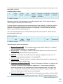
In order for accurate heading information to be developed, the local magnetic field needs to be input
into the unit. To find local inclination and declination values for your area, use your zip code or lat /
long at this site:
http://www.ngdc.noaa.gov/geomagmodels/IGRF.jsp
Have the site compute your local values and you will see a message similar to this:
CHIMU User Manual Rev G.
33
However, the inclination and declination must be changed to radians before inputting to the unit
(multiply them by PI / 180). For the example data above, the inclination would be 1.022 radians,
declination 0.2199 radians.
The reference vector can be derived from the inclination and declination, or from the information
above. However, the CHIMU requires a unit vector, so the information above must be normalized.
For the example data above:
X = 24156.84 / sqrt (24156.84^2 + 5401.57^2 + 40531.6^2) = 0.5086
Likewise, the entire reference vector would be: (0.5086, 0.1138, 0.8534).
CHIMU User Manual Rev G.
34
5.2.16
SOFTWARE RESET (ID 0x0F)
Software Reset
0x0F
1
Input Message
Performs a soft reset of the unit
Description
ID
Length
Type
Comment
Message
Structure
Byte offset
0
Header
Length
0xAE 0xAE
1
Number format
U1
Scaling
-
Device
ID
id or
0xAA
ID
Package
Checksum
0x0F
See Below
XSUM
Name
Reset
Units
-
Description
If package =
0xAB, the unit will
perform a
software reset.
All non-flash
saved settings will
be cleared to
defaults.
This message will force a soft reset of the unit.
CHIMU User Manual Rev G.
35
5.2.17
UART SETTINGS (ID 0x10)
UART SETTINGS
0x10
6
Input Message
Allows setting of UART rate and message mask
Description
ID
Length
Type
Comment
Message
Structure
Header
Length
0xAE 0xAE
6
Byte offset
0
Number format
U1
1
3
4
5
Device
ID
id or
0xAA
ID
Package
Checksum
0x10
See Below
XSUM
Scaling
-
Name
Rate
Units
-
X2
-
Mask
-
Description
0 = 1 Hz
1 = 5 Hz
2 = 10 Hz
3 = 20 Hz
4 = 25 Hz
5 = 50 Hz
6 = 100Hz*
Mask of bits for
entire output
message
structure.
See below for
more information
U1
U1
U1
-
Reserved
Reserved
Clear / write /
save to flash
-
0x00 = Clear all
settings from
flash
0x01 = write
settings until next
power up
0xAB = will write
and save to flash.
* 100 Hz output rate is supported at this time. However, messages must be reduced to only
messages 2 and 3 (sensor and attitude).
The CHIMU UART baud rate is currently fixed at 115kbaud. However, the output rate and message
selection can be changed to help users with integrating the unit into their system.
Message Mask:
All messages may be turned off if desired thru use of a message mask. This mask enables or
disables the ability of the unit to output certain messages. The mask should typically only be used to
turn output messages 0x01, 0x02, 0x03, 0x07 on or off. These are the messages output from the
unit during normal operation.
The mask bits correspond to the output message id numbers. So message 0x01 (Raw Output) is bit
1, message 0x02 is bit 2, etc.
The default is starting with SW version 2.0 is all except raw data (msg 0x01), or 0xFFFD.
CHIMU User Manual Rev G.
36
To turn on all messages, the mask should be 0xFFFF.
The mask to turn off message 0x01, 0x02, and 0x07 is: 0xFF79
UART Recommendations:
The maximum rate on the UART bus is 50Hz. At 50Hz, it is recommended that a mask be applied to
turn off all messages except the Attitude (0x03) message to reduce data processing by the host
processor. The Attitude message contains attitude information as well as attitude rate information
which typically necessary for control of a vehicle.
For 200 Hz data output, implement the SPI bus.
UART Method for Low Rate Queries
If polling only approach to using the unit is to be taken, the user should set the update rate to the
maximum 50Hz rate and use the “Ping” command to request individual messages. In this case, the
CHIMU will respond within 20 milliseconds to a received request. This method is not recommended
for high rate data output.
CHIMU User Manual Rev G.
37
5.2.18
Description
ID
Length
Type
Comment
RESERVED (ID 0x11)
RESERVED
0x11
N/A
Input Message
DO NOT USE THIS MESSAGE ID
Do not send message ID 0x11. This is a reserved factory message capability for the unit.
CHIMU User Manual Rev G.
38
5.2.19
USER PIN OPTION SET (ID 0x12)
User Pin Option Select
0x12
6
Input Message
Allows user to define what action pin 20 performs
when pulled low. Version 1.4 SW and above only.
Description
ID
Length
Type
Comment
Message
Structure
Byte offset
0
1
2
3
4
5
Header
Length
0xAE 0xAE
6
Number format
U1
U1
U1
U1
U1
U1
Scaling
-
Device
ID
id or
0xAA
ID
Package
Checksum
0x12
See Below
XSUM
Name
Option Select
Spare1
Spare2
Spare3
Spare4
Read / write /
save to flash
Units
-
Description
See below
Also: Disable and
clear pin flash
settings
completely
0x00 = Read
current settings
via output
message ID 10.
0x01 = write
settings and use
pin until next
power up
0x02 = will write
and save to flash.
0x03 = clears
any settings from
flash
Option Select –
Option Select Value
0x00
0x01
0x02 – 0xFF
Function when Pin 20 is
pulled low
No functions
UART 1 is disabled and CHIMU
pins are changed to open drain
pins.
This is useful when used with
the Monkey unit for example,
and CHIMU com is handled via
SPI bus. It frees up the serial
port on the Monkey platform for
other functions.
None at this time
Function when Pin 20 is
allowed to go high
No functions
UART 1 is enabled
None at this time
CHIMU User Manual Rev G.
39
5.2.20
GPS / Substituted Heading Replacement (ID 0x13)
Internal Heading Replacement
0x13
5
Input Message
Allows user (when in Euler estimator) to replace
magnetometer data heading with GPS velocity
heading. Version 1.4 SW and above only.
Description
ID
Length
Type
Comment
Message
Structure
Header
Length
0xAE 0xAE
5
Byte offset
0
Number format
U1
1
R4
Device
ID
id or
0xAA
ID
Package
Checksum
0x13
See Below
XSUM
Scaling
-
Name
Enable / Disable
Units
-
Description
0x00 = Do not
use / disabled
-
GPS Heading
degrees
0x01 = Use value
This option is only valid when using the Euler estimator.
In high magnetic environments (high current, ferrous metal, etc), the magnetometer solution may
become corrupted or invalid.
This message allows the user to replace the yaw correction within the CHIMU filters that is typically
performed using the magnetometers with GPS heading. This input value represents the actual
heading of the unit, typically returned from a GPS unit as “Course over Ground” or similar.
An update is sent with the first field (“enable / disable”) set to “1”. The last value associated with a
valid “use value” field is maintained until either a new update is provided or an update disabling the
feature is sent. Because of this, high rate repetition of stale data is not needed.
Note that heading is in degrees, not radians to make it easier to interface to other systems.
Do not send updates faster than 5 Hz.
CHIMU User Manual Rev G.
40
5.2.21
Advanced Magnetometer Calibration (ID 0x14)
Name
Advanced Magnetometer Calibration
0x14
Message
Description
ID
Length
Type
Comment
Message
Structure
Input Message
Overwrites magnetometer cal with offboard
parameters
Header
Length
0xAE 0xAE
65
Byte offset
0
Number format
U1
1
Device
ID
id or
0xAA
ID
Package
Checksum
0x14
See Below
XSUM
Scaling
-
Name
Read /
Write/Save
Units
-
Description
0 = Requests a
read
1 = temporary
write
2 = save to flash
R4
-
-
13
R4
-
Magnetometer
bias
Magnetometer
scale factor
25
R4
-
-
61
R4
-
Soft iron /
misalignment
matrix
Fieldstrength
-
Normalizes output
to +/- 1.0.
Multiply by field
strength for actual
values output
3x3 matrix
uTesla
Local field
strength during
calibration”
Typically, these settings are only able to be accurately set using the algorithms in our Graphical User
Interface.
CHIMU User Manual Rev G.
41
5.2.22
Reserved Messages 0x15 and 0x16
Name
Reservevd
0x15,0x16
Message
Description
ID
Length
Type
Comment
Message
Structure
Input Message
Do not use
Header
Length
0xAE 0xAE
Byte offset
Number format
Scaling
Device
ID
id or
0xAA
ID
Package
Checksum
0x15, 0x16
See Below
XSUM
Name
Units
Description
Do not use these message ID’s.
CHIMU User Manual Rev G.
42
5.2.23
User Orientation Definition (ID 0x17)
Name
User Orientation Definition
0x17
16
Input Message
Writes and stores to flash the rotation from
CHIMU body axis to customer orientation.
Typical (default) is 1,0,0,0 (i.e. no orientation
change from CHIMU body)
Message
Description
ID
Length
Type
Comment
Message
Structure
Byte offset
0
4
8
12
Header
Length
0xAE 0xAE
16
Number format
R4
R4
R4
R4
Scaling
-
Device
ID
id or
0xAA
ID
Package
Checksum
0x17
See Below
XSUM
Name
q0
qx
qy
qz
Units
-
Description
Quaternion scalar
Quaternion x
Quaternion y
Quaternion z
Writes and saves to flash the quaternion that rotates from the CHIMU body frame to the user frame.
This can be used to have the CHIMU output data and attitude in the user frame if installation of the
CHIMU requires an different orientation.
For example, if the CHIMU is installed at a 45 degree angle from the assembly level orientation, this
message can be used to output level results instead of a 45 degree tilted output.
Sending a 1,0,0,0 for the quaternion returns the device to reporting in the CHIMU body frame.
Recommended for experience users only!
CHIMU User Manual Rev G.
43
6. Output Message Details
Shown in this section are the specific message descriptions for output messages from the unit.
6.1 Fixed Message Output
The current message set is fixed with respect to mode. All messages for a given mode are output at
a fixed rate (default is 25 Hz) unless altered by the UART settings mask. The modes and messages
in that mode are as follows:
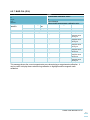
Table 5. Default Messages Output Per Mode
Mode
INIT
Messages
Single Message or Persistent?
Ping (0x00)
Single
Bias and Scale Factor (0x04)
Single
RUNNING
Scaled sensor values (0x02)
Persistent
Attitude (0x03)
Persistent
Gyro Bias (0x07)
Persistent
*Raw values (0x01)
Persistent
ACCEL CAL
Scaled sensor values (0x02)
Persistent
MAG CAL
Mag Cal (0x06)
Persistent
Bias and Scale Factor (0x04)
Persistent
SF Check
SF Check (0x0F)
Persistent
TEMP CAL
Temp Cal (0x08)
Persistent
*As of SW version 2.0 (CHIMU –J), raw messages are off by default to minimize UART and SPI
traffic. They can be re-enabled using the UART mask function for UART, but are permanently off
in SPI output to reduce interrupt load on an external processor.
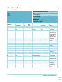
6.2 Output Messages
The output messages from the unit are shown in this summary table:
Table 6. CHIMU Message Output
Name
Ping
ID
0
Length
5
Description
“I’m alive” message with software version
number
Raw counts from sensors
Floating point values
Attitude data, including bit that indicates
quaternion or Euler output is prime
Bias and Scale Factor for all sensor
channels
Indicates active mode
Magnetometer calibration data
Rate sensor biases calculated by estimator
Output during temperature calibration
showing data results
IMU Raw
IMU FP
Attitude
1
2
3
22
48
59
Bias and Scale Factor 4
66
Mode / BIT
Magnetometer Cal
Gyro Bias
Temperature Cal Data
5
6
7
8
2
12
12
35
DAC Offsets
User Pin Select
Option
Advanced Magnetic
9
10
6
Returns settings for user pin select options
11
TBD
Returns magnetic calibration data (repeat of
CHIMU User Manual Rev G.
44
Calibration Data
RESERVED
Mag Ref Vector
Scale Factor Check
RESERVED
User Orientation
12– 13
14
15
16
17
20
12
16
message 4, bias and scale factor, but with
added soft iron and cal data for advanced
magnetometer calibration)
Reserved for future messages
Current magnetic reference stored on unit
Allows check of rate sensor scale factor
Shows the currently stored user orientation
quaternion.
Note: The length shown in this section is the package / payload length for that message. It does not
include the header characters (0xAEAE), length byte, device ID byte, message ID byte, or checksum
byte.
CHIMU User Manual Rev G.
45
6.2.1 PING (ID 0)
Name
Ping
0
5
Output Message
“I’m alive” kind of message, sent during boot and
at request of user, has an identifiable ASCII
character (!) that allows use of a terminal program
to verify UART is active.
Message
Description
ID
Length
Type
Comment
Message
Structure
Header
Length
0xAE 0xAE
3
Byte offset
0
Number format
U1
1
Device
ID
(U1)
ID
Package
Checksum
0
See Below
XSUM
Scaling
-
Name
I’m Alive
Units
-
U1
-
SW Major
-
2
U1
-
SW Minor
-
3
U2
-
Unit Serial
Number
-
Description
0x23 –
Exclamation point
character
Major software
version identifier
Minor software
version identifier
Factory loaded
serial number
This message appears on boot and at request (via ping request input message). It responds with “!”
and the byte values for the onboard software major and minor values.
CHIMU User Manual Rev G.
46
6.2.2 IMU RAW (ID 1)
Name
Raw sensor data
1
22
Output Message
Raw sensor data output, no scale factors or
biases applied. Useful for education or external
filter development. No calibrations are applied to
this data; it is simply raw ADC counts.
Message
Description
ID
Length
Type
Comment
Message
Structure
Header
Length
0xAE 0xAE
22
Byte offset
0
Number format
U2
2
Device
ID
(U1)
ID
Package
Checksum
1
See Below
XSUM
Scaling
-
Name
CPU Temp
Units
-
U2
-
ACC X
-
4
U2
-
ACC Y
-
6
U2
-
ACC Z
-
8
I2
-
MAG X
-
10
I2
-
MAG Y
-
12
I2
-
MAG Z
-
14
U2
-
RATE X
-
16
U2
-
RATE Y
-
18
U2
-
RATE Z
-
20
U2
-
SPARE 1
-
Description
Internal CPU
temp ADC counts
Accelerometer X
raw counts
Accelerometer Y
raw counts
Accelerometer Z
raw counts
Magnetometer X
raw counts
Magnetometer Y
raw counts
Magnetometer Z
raw counts
Gyro X raw
counts
Gyro Y raw
counts
Gyro Z raw
counts
ANA1 ADC read
CHIMU User Manual Rev G.
47
6.2.3 IMU FP (ID 2)
Name
Floating point IMU sensor data
2
48
Output Message
Scaled, bias removed data based on attitude
estimator calculations.
Message
Description
ID
Length
Type
Comment
Message
Structure
Header
Length
0xAE 0xAE
48
Byte offset
0
Number format
R4
4
8
12
16
20
24
28
32
36
40
44
R4
R4
R4
R4
R4
R4
R4
R4
R4
R4
U4
Device
ID
(U1)
ID
Package
Checksum
2
See Below
XSUM
Scaling
-
Name
CPU Temp
Units
°C
0.005
ACC X
ACC Y
ACC Z
RATE X
RATE Y
RATE Z
MAG X
MAG Y
MAG Z
SPARE 1
Time
m/s2
2
m/s
m/s2
rad/s
rad/s
rad/s
Gauss
Gauss
Gauss
sec
Description
Internal CPU
temperature
Accel X
Accel Y
Accel Z
Gyro X
Gyro Y
Gyro Z
Magnetic X
Magnetic Y
Magnetic Z
ANA1 ADC read
Time since turn
on (internal CPU
timer)
CHIMU User Manual Rev G.
48
6.2.4 Attitude (ID 3)
Name
Attitude and Heading estimates
3
59
Output Message
Contains Euler and Quaternion estimates of
current attitude.
Message
Description
ID
Length
Type
Comment
IMPORTANT:
Estimator choice defines which set of data (Euler,
Quaternion) is valid!
Message
Structure
Header
Length
0xAE 0xAE
59
Byte offset
0
4
8
Number format
R4
R4
R4
12
Device
ID
(U1)
ID
Package
Checksum
3
See Below
XSUM
Scaling
-
Name
PHI
THETA
PSI
Units
rad
rad
rad
R4
-
Phi Dot
rad/s
16
20
24
R4
R4
R4
-
Theta Dot
Psi Dot
q0
rad/s
rad/s
-
28
32
36
40
R4
R4
R4
R4
-
q1
q2
q3
q0 dot
-
Description
Roll angle
Pitch angle
Yaw angle
(Reported True
North if reference
vector has been
applied, else
magnetic north)
Roll angle rate
(identical to
scaled sensor
value)
Pitch angle rate
Yaw angle rate
Quaternion
(scalar)
Quaternion x
Quaternion y
Quaternion z
Rotation rate
quaternion
44
48
52
56
R4
R4
R4
X1
-
q1 dot
q2 dot
q3 dot
Calibration Status
-
57
X1
-
Built In Test (BIT)
-
58
X1
-
Configuration Info
-
See below for
breakdown of
calibration status
byte
See below for
breakdown of BIT
status byte
See below for
breakdown of
Config Info status
byte
CHIMU User Manual Rev G.
49
The calibration status byte is a bit field reflecting the state of the unit’s internal calibration. Shown below is the
interpretation of this byte:
Calibration Status bit fields:
bit 7
X
bit 6
Custom
UART
bit 5
Gyro Bias
Saved
bit 4
DAC
offsets set
bit 3
Magnetic
reference
information
set
bit 2
Temperature
calibrated
rate sensors
bit 1
Magnetometers
calibrated
bit 0
Accelerometers
calibrated
1 = TRUE, 0 = FALSE
Description of the bits is self explanatory by their titles except for bit 6. This bit indicates special
UART settings have been saved to flash memory.
For basic operation, magnetometers and accelerometers must be calibrated. For precise operation,
magnetic reference information must also be set. For faster startup and temperature insensitive
operation, the temperature calibration bit needs to be completed. The DAC offsets are an added
feature, and do not affect estimate operation.
The built in test (BIT) status byte is a bit field reflecting the error state of the unit. Shown below is
the interpretation of this byte:
BIT Status bit fields:
bit 7
X
bit 6
I2C BUS
FAIL
bit 5
WATCHDOG
TIMER
RESTART
bit 4
TEMP CAL
READY
FAIL
bit 3
CAL FAIL
bit 2
UART FAIL
bit 1
SINGULARITY
FAIL
bit 0
MAG
SATURATION
1 = TRUE, 0 = FALSE
These bits require some more discussion:
1) Magnetic Saturation BIT – If the magnetometers saturate, this bit will be set. It is cleared
after one reporting message (i.e. non latching BIT)
2) Singularity BIT – If a singularity condition in the attitude estimate occurs, this bit will be set
to indicate a degraded estimate may be being output
3) UART BIT – If set, there was a buffer overrun or improper message sent to the unit. It is
cleared after one reporting message (i.e. non latching BIT)
4) Calibration BIT – If there is a failure to complete a calibration process that could leave bad
results in flash memory, this bit is set.
5) Temperature Calibration Ready BIT – Set when Temperature Calibration is in progress and
if there are no results to allow temperature calibration yet. If the temperature calibration
process is started at too high a temperature to allow enough data points, this bit will never
clear. If it does clear, the temperature calibration was successful enough to establish new
values into flash memory and the process can be stopped.
6) Watchdog Timer Restart – Indicates that the unit has had to recover from a locked condition
and its watchdog timer was engaged to reset the unit. This BIT is typically flagged on start,
CHIMU User Manual Rev G.
50
as a power down of the system can erroneously set this bit. Powered, in run operation of the
unit should not see this bit flagged. Check all inputs if it is flagged after startup.
7) I2C BUS Fail – The internal I2C bus can get locked by devices on the chip under some
circumstances. In most situations, the bus is cleared and reset in less than 50 milliseconds.
If this occurs, however, this bit is set to indicate the problem.
The configuration information status byte is a bit field reflecting the configuration state of the unit.
Shown below is the interpretation of this byte:
Configuration Info Status bit fields:
bit 7
Allow
Hardware
Pin Config
Override
bit 6
SW
Centripetal
Velocity
Active
bit 5
Estimator
Type
bit 4
TBD
bit 3
Rate / Angle Out
Configuration
bit 2
Temp calibration
active
bit 1
HW
Centripetal
Velocity
Active
bit 0
SPI
Enabled
1 = TRUE, 0 = FALSE
These bits require some more discussion:
Hardware Pin Configuration Override – If this bit is set (default), then the hardware pins for
centripetal velocity, temperature calibration, and SPI enabling are active. The configuration
can be changed by the status of these pins at boot. This can be disabled thru use of the
configuration set message.
SW Centripetal Velocity Active – set when software velocity messages are being sent and
used
Estimator type – 0 = Euler estimator, 1 = Quaternion estimator
TBD bit is reserved for future use
Rate / Angle out – 0 = angle output on DAC channels, 1 = rate output on DAC channels
Temp calibration active – 0 = false, 1 = true
HW Centripetal Velocity Active – set when hardware channel is being used for forward
velocity input. Represents status of hardware enable pin, but can be prevented if configured
to ignore this pin.
SPI Enabled – 0 = false, 1 = true
CHIMU User Manual Rev G.
51
6.2.5 Bias and Scale Factor (ID 4)
Name
Bias and Scale Factor
4
66
Output Message
Outputs bias and scale factor for all sensors
Message
Description
ID
Length
Type
Comment
Message
Structure
Header
Length
0xAE 0xAE
66
Byte offset
0
Number format
I2
Scaling
-
2,4,6
I2 * 3
-
8,10,12
14, 16, 18
I2 * 3
I2 * 3
-
20
I2
-
22
26,30,34
R4
R4 * 3
38,42,46
50,54,58
62
Device
ID
(U1)
ID
Package
Checksum
4
See Below
NONE
Name
Temp Sensor
Bias
Accel X, Y, Z bias
Units
-
Description
Do not change
m/s^2
Rad/s
Local gauss
(normalized)
-
Rate Sensor bias
Magnetometer
bias
Hardware analog
1 read (velocity
input) bias
Temp Sensor SF
Accel X, Y, Z SF
Note: 3 integers,
one for each axis
“”
“”
R4 * 3
R4 * 3
-
Rate Sensor SF
Magnetometer SF
Rad/s
Local gauss
(normalized)
R4
-
Hardware analog
1 read (velocity
input) SF
m/s^2
Note: 3 floating
point values, one
for each axis
“”
“”
Scale as needed
for external
hardware speed
input.
This message is output during magnetometer calibration automatically, and at request typically.
Boot values for the rate sensors in this message will typically be zero as it is output before
calculation. Therefore, requesting this message after run mode has been entered is the best method
for obtaining the full correct set of data if needed.
CHIMU User Manual Rev G.
52
6.2.6 Mode / BIT (ID 5)
Name
Mode indicator and BIT results
5
2
Output Message
Output only when mode changes
Message
Description
ID
Length
Type
Comment
Message
Structure
Header
Length
0xAE 0xAE
2
Byte offset
0
Number format
U1
1
U1
Device
ID
(U1)
ID
Package
Checksum
5
See Below
XSUM
Scaling
-
Name
Mode
Units
-
-
BIT
-
Description
Mode:
0 – INIT/BOOT
1 – RUNNING
2 – ACC CAL
3 – MAG CAL
4 – SF CHECK
5 – TEMP CAL
BIT decoded per
description below
The BIT message can be decoded per Message 3, as they are identical.
CHIMU User Manual Rev G.
53
6.2.7 MAG CAL (ID 6)
Name
Magnetometer calibration values
6
12
Output Message
Output during magnetometer calibration only.
Message
Description
ID
Length
Type
Comment
Message
Structure
Header
Length
0xAE 0xAE
12
Byte offset
0
Number format
I2
2
Device
ID
(U1)
ID
Package
Checksum
6
See Below
XSUM
Scaling
-
Name
MagXmin
Units
gauss
I2
-
MagYmin
gauss
4
I2
-
MagZmin
gauss
6
I2
-
MagXmax
gauss
8
I2
-
MagYmax
gauss
10
I2
-
MagZmax
gauss
Description
Min x axis
magnetic value
during cal
Min y axis
magnetic value
during cal
Min z axis
magnetic value
during cal
Max x axis
magnetic value
during cal
Max y axis
magnetic value
during cal
Max z axis
magnetic value
during cal
This message shows the current magnetometer raw values during a magnetometer calibration. It
can be useful to display these values during calibration to highlight sensitive magnetic north
calibration.
CHIMU User Manual Rev G.
54
6.2.8 GYRO BIASES (ID 7)
Name
Gyro Bias Values
7
12
Output Message
Provides running calculated biases for rate
sensors
Message
Description
ID
Length
Type
Comment
Message
Structure
Header
Length
0xAE 0xAE
12
Byte offset
0
Number format
R4
4
8
Device
ID
(U1)
ID
Package
Checksum
7
See Below
XSUM
Scaling
-
Name
Rate X bias
Units
rad/s
R4
-
Rate Y bias
rad/s
R4
-
Rate Z bias
rad/s
Description
X gyro bias
calculated from
internal estimator
Y gyro bias
calculated from
internal estimator
Z gyro bias
calculated from
internal estimator
CHIMU User Manual Rev G.
55
6.2.9 TEMPERATURE CALIBRATON DATA (ID 8)
Name
Temperature Calibration Data
8
35
Output Message
Provides latest temperature calibration statistics
during temp cal run
Message
Description
ID
Length
Type
Comment
Message
Structure
Header
Length
0xAE 0xAE
35
Byte offset
0, 2,4
Number format
I2
6,10,14
Device
ID
(U1)
ID
Package
Checksum
8
See Below
XSUM
Scaling
-
Name
Bias
Units
-
R4
-
Scale Factor
-
18,22,26
R4
-
Correlation
Coefficient
-
30
R4
-
Temperature
C
34
U1
-
Data Points
-
Description
Bias for x,y,z rate
sensors based on
temperature
calibration routine
in effect
Scale factor for
same
Figure of merit for
correlation of
temperature
calibration per
channel
Current
temperature
Number of
temperature
points included in
calibration (the
more the better)
Temperature calibration is done prior to shipment. If you need more from this function, contact us
prior to performing please.
CHIMU User Manual Rev G.
56
6.2.10
DAC OFFSET READ (ID 9)
Name
DAC OFFSET READ
9
4
Output Message
Provides offsets stored in flash for output DAC
channels
Message
Description
ID
Length
Type
Comment
Message
Structure
Header
Length
0xAE 0xAE
4
Byte offset
0
Number format
I2
2
I2
Device
ID
(U1)
ID
Package
Checksum
9
See Below
XSUM
Scaling
-
Name
Offset Channel 0
Units
-
-
Offset Channel 1
-
Description
DAC Bias for
channel 0
DAC Bias for
channel 1
DAC offsets are values loaded by the user to modify the output from the DAC channels in rate and
angle output modes. Default should be zero for each channel.
CHIMU User Manual Rev G.
57
6.2.11
USER PIN OPTIONS READ (ID 10)
Name
User Pin Options Read
10
8
Output Message
Provide feedback on user pin option
Message
Description
ID
Length
Type
Comment
Message
Structure
Byte offset
0
Header
Length
0xAE 0xAE
8
Number format
U1
Scaling
-
Device
ID
(U1)
ID
Package
Checksum
10
See Below
XSUM
Name
Function select
Units
-
Description
0x00 = Disabled
(nothing)
0x01 = Disable
UART pins
1
2
3
4
5
6
7
U1
U1
U1
U1
U1
U1
U1
-
Spare1
Spare2
Spare3
Spare4
Aux 1
Aux 2
Aux 3
-
Factory use only
Factory use only
Factory use only
CHIMU User Manual Rev G.
58
6.2.12
MAGNETIC REFERENCE VECTOR (ID 14)
Name
Reports magnetic reference vector unit is using
14
Message
Description
ID
Length
Type
Comment
Message
Structure
Output Message
Reference vector can and should be changed by
user based on location.
Header
Length
0xAE 0xAE
20
Byte offset
0, 4, 8
Number format
R4 * 3
12
16
Device
ID
(U1)
ID
Package
Checksum
14
See Below
XSUM
Scaling
-
Name
Mag reference
vector (x,y,z)
Units
-
R4
-
Declination
rad
R4
-
Inclination
rad
Description
Unit vector
describing local
magnetic field
Local magnetic
declination
Local magnetic
inclination
This data can and should be tailored for a specific location if accurate heading is desired. Use the
magnetic reference vector input message to change and save this information.
CHIMU User Manual Rev G.
59
6.2.13
RATE SENSOR SF CHECK (ID 15)
Name
Allows check of rate sensor scale factor
15
12
Output Message
Outputs integrated rate sensor data if enabled
with rate sensor check command
Message
Description
ID
Length
Type
Comment
Message
Structure
Header
Length
0xAE 0xAE
12
Byte offset
0
Number format
R4
4
8
Device
ID
(U1)
ID
Package
Checksum
15
See Below
XSUM
Scaling
-
Name
Integrated roll
angle
Units
rad
R4
-
Integrated pitch
angle
rad
R4
-
Integrated yaw
angle
rad
Description
Roll rate sensor
integrated from
start of mode
entry
Pitch rate sensor
integrated from
start of mode
entry
Yaw rate sensor
integrated from
start of mode
entry
CHIMU User Manual Rev G.
60
6.2.14
RESERVED (ID 16)
Name
Special customer message
16
Message
Description
ID
Length
Type
Comment
Message
Structure
Output Message
Will not be seen by average customer
Header
Length
0xAE 0xAE
Byte offset
Number format
Scaling
Device
ID
(U1)
ID
Package
Checksum
16
See Below
XSUM
Name
Units
Description
CHIMU User Manual Rev G.
61
6.2.15
USER ORIENTATION (ID 17)
Name
Shows quaternion from CHIMU installation to user
coordinate frame.
17
16
Output Message
Outputs quaternion that transforms from CHIMU
body frame to user body frame
Message
Description
ID
Length
Type
Comment
Message
Structure
Byte offset
0
4
8
12
Header
Length
0xAE 0xAE
16
Number format
R4
R4
R4
R4
Scaling
-
Device
ID
(U1)
ID
Package
Checksum
17
See Below
XSUM
Name
q0
qx
qy
qz
Units
-
Description
Quaternion scalar
Quaternion x
Quaternion y
Quaternion z
CHIMU User Manual Rev G.
62
7. Software Reprogramming
The CHIMU- J board can be reprogrammed in the field if necessary. In order to accomplish this, the
user will have to pull down the ISP pin upon powering up. This puts the processor into boot loader
mode, and new firmware can be uploaded via serial port. Please contact us for more details.
CHIMU User Manual Rev G.
63
8. Appendix A: Quaternion vs. Euler Estimator
The following only applies to earlier CHIMU units that allowed Euler or Quaternion filter selection.
For dynamic situations where 3D rotations are expected to occur (rockets, tumbling vehicles, etc.),
the quaternion estimator is the best choice.
Stable implementations that will not spend significant time pointed at +/- 90 degree pitch orientation
may use the Euler formulation as well.
In Quaternion mode (the default), only quaternion and quaternion rate outputs occur. To transform
these into standard Euler angles, it is recommended to use the following transformation pseudo
code.
Sub Get_Euler_From_Quat(&v As EULER_STRUCT, &q As QUATERNION_STRUCT)
{
float x, sqw,sqx,sqy,sqz,norm;
sqw = q.w * q.w;
sqx = q.x * q.x;
sqy = q.y * q.y;
sqz = q.z * q.z;
norm = sqrt(sqw + sqx + sqy + sqz);
//Normalize
q.w = q.w /
q.x = q.x /
q.y = q.y /
q.z = q.z /
}
the quat
norm;
norm;
norm;
norm;
v.phi =atan2(2.0 * (q.w * q.x + q.y * q.z), (1 - 2 * (sqx + sqy)));
If (v.phi < 0) Then v.phi = v.phi + 2 *PI;
x = ((2.0 * (q.w * q.y - q.z * q.x)));
//Below needed in event normalization not done
If (x > 1.0) x = 1.0;
If (x < -1.0) x = -1.0;
//
If ((q.x * q.y + q.z * q.w) = 0.5) {
v.theta = 2 *atan2(q.x, q.w);
}elseif{
((q.x * q.y + q.z * q.w) = -0.5) Then
v.theta = -2 *atan2(q.x, q.w);
}else{
v.theta = asin(x)
}
v.psi = atan2(2.0 * (q.w * q.z + q.x * q.y), (1 - 2 * (sqy + sqz)));
If (v.psi < 0) Then v.psi = v.psi + (2 * PI);
CHIMU User Manual Rev G.
64
9. Appendix B: Temperature Calibration
With no calibration, the unit will snapshot the biases on the rate sensors at power up, assuming that
the unit is motionless so that accurate initial bias estimates can be used. If the unit is not
temperature calibrated however, then any motion on the unit during power up will result in biases
that will affect the solution, usually very dramatically! The CHIMU dynamic estimator is constantly
estimating biases for the sensitive components and can remove small initial rates within
approximately 30 to 60 seconds.
However, to minimize startup time, the unit should be temperature calibrated. This allows the unit to
compute the expected biases based on temperature. This can be done to the unit before shipping,
or can be performed by the user to a basic unit.
The calibration process consists of the very basic sequence that follows:
1) Place the unit in a cool environment (i.e. refrigerator or even freezer)
2) Remove the unit from the environment and power it up
3) Using our control software or user software, send the temperature calibration command
a. Once the calibration command is sent, the unit MUST REMAIN ABSOLUTELY
MOTIONLESS UNTIL CALIBRATION IS COMPLETE!
4) Once the unit has reported at least 3 temperature snapshots, the unit may be commanded to
end calibration.
a. At least 30 degrees of temperature change from start to finish should be experienced
for best results.
b. We also recommend that you allow the unit to heat up to at least nominal
temperature, but preferably the normal operational temperature or above for best
results
5) The coefficients are saved to flash memory and are active from this point forward at startup.
For extremely accurate operation at a specific operating temperature, please see the next appendix.
CHIMU User Manual Rev G.
65
10. Appendix C: Set Point Calibration
Even with temperature calibration, the unit will have to “learn” biases during operation. These are
the result of magnetometer or accelerometer calibration inconsistencies that may not be noticeable
to the user, as well as inherent changes that can occur in the unit over time.
To obtain the very best operation (i.e. minimal startup time) at a certain operating temperature and
environmental conditions, we recommend the following:
1) Perform the temperature calibration prior to this
2) Allow the unit to operate until steady state is achieved on the gyro bias estimates
3) Send message 0x08, Gyro Bias Save, to the unit
The bias values will be saved to flash memory and will be used on every power up after this.
These values can be cleared from flash if the desired biases change over time.
We do not recommend using this for most applications. Most applications do not need this and
saving these biases may not be the optimal settings for different usage of the unit.
CHIMU User Manual Rev G.
66
11. Appendix D: Accelerometer Calibration
In order to calibrate accelerometers on the CHIMU using our GUI (available for free online at
www.ryanmechatronics.com) , simply follow the steps below:
1) Connect to the CHIMU using the serial port per normal use (USB Node recommended)
2) On the Calibration page, find the Accelerometer Calibration panel:
3) Place the unit level (recommend using a bubble level at a minimum, or precision surface
such that the unit is known to be level)
4) Click on “Unit Level”. The indicator next to it will turn green.
5) It is important that you now proceed thru the next 5 positions in order, clicking the button
when the unit is in that position and stable (unmoving).
6) When you click on the last item “Right Wing Up”, calibration will be complete and settings will
be saved to flash memory.
7) Verify your calibration by using the graphs page and checking gravitational acceleration is
registering correctly on all axes.
CHIMU User Manual Rev G.
67
12. Appendix E: Magnetometer Calibration
In order to calibrate magnetometers on the CHIMU using our GUI (available for free online at
www.ryanmechatronics.com) , simply follow the steps below. Most applications need only the basic
calibration method.
12.1 Basic Calibration – Hard Iron calibration
1) Connect to the CHIMU using the serial port per normal use (USB Node recommended)
2) On the Calibration page, find the Magnetometer Calibration panel:
3) Hold the unit far away (at least 1 foot, the more the better) from magnetic influences like
steel, magnets, computer monitors, PC speakers, etc.
4) Click on “Start Mag Cal”. The fields next to it will show instant magnetometer values.
5) Rotate the unit about each axis, with the rotation being towards North.
6) The purpose is to expose the unit to the strongest earth magnetic field that exists in your area
7) Repeat for each axis until you no longer see any significant change in the min and max fields
8) When this is complete, click on “END Mag Cal”.
9) Calibration will be complete and settings will be saved to flash memory.
10) Verify your calibration by using the graphs page and checking that magnetic field strength
lies within +/- 1 on all axes.
CHIMU User Manual Rev G.
68
12.2 Advanced Calibration – Hard and Soft Iron Calibration
Some applications may have a large amount of soft iron influence. If the basic calibration does not
provide the results required, then using the advanced calibration routine can be attempted.
Note that this method can easily induce more error into the system if the procedure is not followed
correctly or if other field disturbances come into play during the calibration.
The unit should be calibrated while installed in the final assembly.
1) Connect to the CHIMU using the serial port per normal use (USB Node recommended, or the
actual serial interface of the unit as installed in the customers equipment).
2) Normal calibration item looks like this:
3) Click “Advanced Cal” to access soft iron calibration. When you do so, the fine tune dialog will
also show up.
4) You MUST do a soft iron “tumble” calibration first. To do this, you click on “START MAG
CAL” and then tumble the unit in all three dimensions. This tumble is different than the hard
iron tumble. We recommend a single yaw rotation performed along each axis. For example:
a. Face the unit, while level, north (or any other heading, but remember where you
start). In this case, the X axis of the CHIMU faces north, the Z axis faces down.
Rotate it slowly over 360 degrees in inertial yaw (i.e. keep the Z axis pointed down as
you rotate the X axis thru all 360 degrees of heading). Perform two rotations if
possible.
b. Facing north (or any other heading, but remember where you start), rotate the CHIMU
in roll such that X still faces north, but Y is now facing down instead of Z. Keeping it
in this orientation, once again rotate it slowly over 360 degrees in inertial yaw (i.e.
CHIMU User Manual Rev G.
69
keep the Y axis pointed down as you rotate the X axis thru all 360 degrees of
heading).
c. Finally, facing north (or any other heading, but remember where you start), rotate the
CHIMU from level in pitch such that Z now faces north, but X is now facing up. In
other words, the CHIMU “nose” is pointed up. Keeping it in this orientation, once
again rotate it slowly over 360 degrees in inertial yaw (i.e. keep the X axis pointed UP
as you rotate the Z axis thru all 360 degrees of heading).
5) When you are done with the motion, press “END MAG CAL”. You should get a dialog box if
successful that looks something like the below. Note that the soft iron matrix is symmetric
(with generally large numbers along the diagonal).
6) The unit now has hard and soft iron corrections in place. Further fine tuning can be
performed for better accuracy as shown in the next section.
12.3 Advanced Calibration – Hard and Soft Iron Calibration with fine
correction
1) Now, place the unit so that it faces north. It is critical that this process be performed as
follows:
a. LEVEL ATTITUDE with the CHIMU PINS FACING DOWN and
the CHIMU X AXIS pointed to North.
b. CHIMU should be pointed to MAGNETIC NORTH! NOT
CARTOGRAPHIC OR TRUE NORTH! THIS IS CRITICAL FOR
THIS STEP AND THE FOLLOWING THAT YOU USE MAGNETIC
DIRECTIONS, NOT LOCAL NSEW!
CHIMU User Manual Rev G.
70
c. Image below is an example of the CHIMU on an iron block facing north.
2) Press the “N” button under “Adv Cal Fine Tune”. The light should go from RED to GREEN as
shown below:
3) For the North button, you will always get this reminder:
4) IF you incorrectly log a direction, press “RESET” and start over at North.
5) Proceed with the remaining directions.
d. NOTE: You do not have to do the remaining directions in order.
CHIMU User Manual Rev G.
71
e. TIP! The North and East directions are the most critical to the fine tune process.
Care should be made to identify those directions well in your calibration setup.
6) When you are done, the dialog should look like this:
7) The final step is to press “COMMIT”. When you do this, a corrected matrix will be sent to the
CHIMU and saved in flash. You will get a dialog that looks like the below. Note that the
matrix is no longer symmetric.
CHIMU User Manual Rev G.
72