1
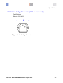
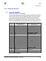
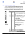
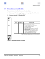
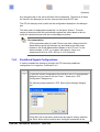
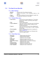
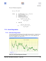
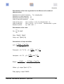
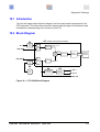
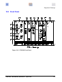
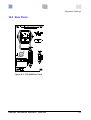
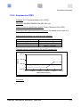
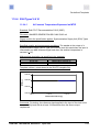
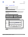
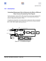
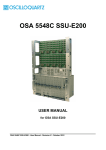
Diagrams & Drawings
10.1 Introduction
The next few pages show the block diagram, the front panel and the back panel of the
STS instrument. This information shows the names used throughout this document and
facilitates the understanding of the function of the STS.
10.2 Block Diagram
A5 - Phase measurement module
A2
IN
TEX
or LR
AUX IN
INPUT
MUX
SYNTH.
80'080 Hz ± dF
80 Hz
± dF
COUNTER
EXT REF
G
Rb
REF
MUX
DIVIDER
MICROCONTROL
RS-232
PC with
WinSTS
software
80'000 Hz
A6
Rb
REF
A4
A3
FREQUENCY
CHANGER
OUTPUT
MODULE
OUT 1
OUT 2
REF OUT
Figure 10-1 : STS 5565 Block Diagram
OSA 5565 User Manual Revision A
April 2010
10-3