1
CALIFORNIA STATE UNIVERSITY, NORTHRIDGE
FPGA-BASED DISTRESS SIGNAL GENERATION WITH GPS TRACKING AND
SMS TEXT MESSAGES
A project submitted in partial fulfillment of the requirements
For the degree of Master of Science in Electrical Engineering
By
Alexander Anthony Hale
May 2014
SIGNATURE PAGE
The project of Alexander Anthony Hale is approved:
__________________________________
Dr. Kourosh Sedghisigarchi
___________________
Date
__________________________________
Dr. Sharlene Katz
___________________
Date
__________________________________
Dr. George K. Law, Chair
___________________
Date
California State University, Northridge
ii
TABLE OF CONTENTS
SIGNATURE PAGE .......................................................................................................... ii
LIST OF FIGURES ........................................................................................................... iv
LIST OF TABLES ............................................................................................................. iv
ABSTRACT ........................................................................................................................ v
I.
INTRODUCTION ................................................................................................... 1
II.
SYSTEM ARCHITECTURE .................................................................................. 2
2.1
Hardware Components ......................................................................................... 2
2.1.1
DE0-Nano Board .......................................................................................... 2
2.1.2
GPS Receiver ................................................................................................ 5
2.1.3
Cell Phone ..................................................................................................... 6
2.2
Hardware Schematic ............................................................................................ 7
2.3
Quartus Implementation and Programming the FPGA ........................................ 8
2.3.1
QSYS System Development ......................................................................... 8
2.3.2
System Creation, Pin Placement, and Downloading to FPGA ................... 11
III.
PROTOCOLS AND STANDARDS...................................................................... 13
3.1
Hayes Command Set .......................................................................................... 13
3.2
RS-232 Serial Standard ...................................................................................... 14
3.3
GPS..................................................................................................................... 15
IV.
SOFTWARE .......................................................................................................... 17
V.
RESULTS .............................................................................................................. 20
VI.
CONCLUSION ...................................................................................................... 23
REFERENCES ................................................................................................................. 24
APPENDIX - C Program Code......................................................................................... 26
iii
LIST OF FIGURES
Figure 2.1: DE0-Nano Board .............................................................................................. 3
Figure 2.2: Block Diagram of DE0-Nano Board ................................................................ 3
Figure 2.3: Pin Arrangement of the 40-pin Expansion Headers ......................................... 4
Figure 2.4: Pin 1 Locations of the GPIO Expansion Headers ............................................ 4
Figure 2.5: Motorola C168i Cell Phone Serial Plug ........................................................... 7
Figure 2.6: System Schematic............................................................................................. 7
Figure 2.7: Picture of System.............................................................................................. 8
Figure 2.8: QSYS Diagram of System .............................................................................. 10
Figure 2.9: PIO Interrupt Setup ........................................................................................ 11
Figure 2.10: System Diagram and Pin Placement ............................................................ 12
Figure 3.1: Sample RS-232 Signal Waveform ................................................................. 15
Figure 3.2: UBX Message Structure ................................................................................. 16
Figure 4.1: Program Flowchart ......................................................................................... 17
Figure 4.2: UART Register Map ...................................................................................... 19
Figure 5.1: JTAG UART Output, GPS Coordinates ........................................................ 20
Figure 5.2: JTAG UART Output, AT Commands............................................................ 21
Figure 5.3: Screen Capture of Sent SMS Text Message ................................................... 21
LIST OF TABLES
Table 3.1: AT Commands Used During Project ............................................................... 14
Table 3.2: RS-232 Voltage and Logic Levels ................................................................... 15
Table 3.3: Decoded Sample NMEA $GPGLL Message .................................................. 16
Table 3.4: Message Characteristics Required for Latitude and Longitude ....................... 16
iv
ABSTRACT
FPGA-BASED DISTRESS SIGNAL GENERATION WITH GPS TRACKING AND
SMS TEXT MESSAGES
By
Alexander Anthony Hale
Master of Science in Electrical Engineering
In this report the generation of a FPGA-based distress signal will be explained and
implemented. The signal is sent via SMS text message and will contain the user’s current
GPS coordinates.
Both simulation and experimentation yielded positive results and
confirm that such a signal is possible to generate with only a few simple components.
Several constraints and limitation inherent to this design are identified and addressed.
Modifications that could be made to the system to increase performance are proposed.
v
I.
INTRODUCTION
This report describes a project to develop and implement a system that can send an
SMS text message with a user’s current GPS coordinates as a distress signal. A simple
button press will generate and send the message to a pre-determined phone number. The
system will be created using a Motorola C168i cellular phone, a NEO-6M GPS receiver,
and a DE0-Nano development and education board with a Cyclone IV FPGA. The
primary purpose of this system will be to act as an emergency signal, similar to the Life
Alert® system, but without requiring any voice input.
The idea of combining GPS and SMS messages to accomplish various tasks has been
thought of before. Some of the proposed and completed projects include: navigation
systems for the blind [1][2], generating traffic reports based on the current GPS location
[3], vehicle tracking and management [4]-[6], and personnel tracking [7]. Sending an
SMS message to alert medical facilities and personnel has also been proposed [8].
In addition to system implementation, this report describes the system’s development
and testing. Section 2 discusses the system architecture and hardware used in creating the
system. Section 3 provides background information on the protocols and standards that
were employed. Section 4 examines the software code that was written in support of the
project, including its structure and flow. Section 5 summarizes the project test results as
well as enumerating the complications encountered and how they were overcome.
Section 6 provides the conclusions and gives suggestions for system improvements.
1
II.
SYSTEM ARCHITECTURE
This section will explain in detail how the different hardware components are used
and connected to create the system. This section is divided into three subsections:
hardware components, component interface, and system design and FPGA configuration.
2.1
Hardware Components
Three different hardware components were used for this project: the DE0-Nano
board, a GPS receiver, and a cellular phone.
2.1.1
DE0-Nano Board
The Altera DE0-Nano Development and Education board was the main hardware
component of the system. The DE0-Nano is a small (3x2 inch) board that contains a
Cyclone IV EP4C22 FPGA. It also contains 32 MB of SDRAM, 2 kb EEPROM, and a 52
Mb serial configuration memory device [9]. The 32 MB of SDRAM contained the C
code that was written to perform the necessary functions to send the SMS text message.
The Serial flash memory (EPCS64) on the board was used to hold the code to program
the FPGA while the board was powered off. A USB port is used to program the board,
and can also provide power if the board is not powered by the power header pins. Input
and output sources on the board include expansion headers, two pushbuttons, eight LEDs,
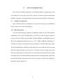
and four dip-switches. The board is shown below in Figure 2.1, and a block diagram of
the board is shown in Figure 2.2.
2
Figure 2.1: DE0-Nano Board
Figure 2.2: Block Diagram of DE0-Nano Board
The expansion headers on the device were used to power the GPS receiver
(discussed in Section 2.1.2) and to communicate with both the GPS receiver and the
GSM modem (discussed in Section 2.1.3). The DE0-Nano board has two 40-pin headers,
which provide 72 input/output pins, 5 V power pins, two 3.3 V power pins, and four
ground pins. Each header is connected directly to the FPGA. The expansion header pin
arrangement and location on the board is shown in Figures 2.3 and 2.4, respectively.
3
Figure 2.3: Pin Arrangement of the 40-pin Expansion Headers
Figure 2.4: Pin 1 Locations of the GPIO Expansion Headers
One of the pushbuttons on the DE0-Nano board was used to initiate the sending of the
SMS text message with the GPS coordinates. These push buttons are de-bounced and
4
connected to the FPGA. They are active low, meaning that a high logic level is present
when they are not being pressed.
The DE0-Nano board has a 50 MHz oscillator, which is connected directly to the
clock input pin of the FPGA. The oscillator is used as a clock source for the system.
2.1.2
GPS Receiver
The GPS receiver used for this project was the NEO-6M module from u-blox [10]. It
is a 50-channel receiver which can lock on to a GPS signal within 27 seconds after the
receiver is powered on. The horizontal position accuracy is stated to be 2.5 meters, which
for the purposes of this project is more than satisfactory.
To deliver the coordinate information, the NEO-6M can utilize three different
protocols: NMEA (the GPS standard, discussed in Section 3), UBX (which is the u-blox
proprietary format, also discussed in Section 3), and RTCM. The UBX system was used
for this project, since it was the simplest to implement. The device has been configured to
output sentences in the UBX format and would require UBX commands to switch to
either the NMEA or RTCM standards.
The NEO-6M supports four different serial interfaces: UART (Universal
Asynchronous Receiver/Transmitter), USB (Universal Serial Bus), SPI (Serial Peripheral
Interface), and an I2C compatible DDC (Display Data Channel) interface. In this project,
the QSYS UART interface was used to communicate with the NEO-6M. The baud rate of
the UART connection was 38400 bps, with no parity bits, eight data bits, and one stop
bit. These selections were pre-programmed for the NEO-6M receiver.
5
The GPS receiver was powered by two of the DE0-Nano board’s expansion header
pins: one for 3.3V and the other for the ground. Another expansion header pin is used to
read the data from the UART.
2.1.3
Cell Phone
In this project, a cell phone is used to send the SMS text message containing the GPS
coordinates. The cell phone used for this project is the Motorola C168i. It is a GSM
phone that operates on the AT&T network with an installed SIM card. A specialized set
of AT commands (discussed in Section 3) can be sent to the phone to perform certain
tasks, like sending an SMS text message.
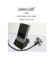
The headset jack on the C168i can function as a TTL serial port [11]. A 3/32” stereo
plug was used to connect the cell phone to the DE0-Nano board, which used a UART
(Universal Asynchronous Receiver/Transmitter) to communicate back and forth. A
diagram of the plug, as well as the TX, RX, and GND connections it needs for the
UART, are shown in Figure 2.5. Wires were soldered to points 1, 2, and 3 for the RX,
TX, and GND connections, respectively. The other ends of the wires were then connected
to the pins on the expansion header of the DE0-Nano board.
The serial messages were sent and received between the FPGA and cell phone using a
UART. The C168i UART port was configured with a baud rate of 4800 bps, no parity bit,
eight data bits, and one stop bit.
6
Figure 2.5: Motorola C168i Cell Phone Serial Plug
2.2
Hardware Schematic
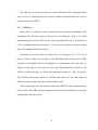
The cell phone and GPS receiver were both connected to the expansion header GPIO
pins on the DE0-Nano board. A schematic of these three hardware components, along
with the rest of the necessary components on the DE0-Nano board, is shown in Figure
2.6. Additionally, a picture of the complete setup is provided in Figure 2.7.
Figure 2.6: System Schematic
7
Figure 2.7: Picture of System
2.3
Quartus Implementation and Programming the FPGA
The system was created and downloaded to the FPGA by using Altera’s Quartus II
software. A new project was created using the Cyclone IV EPC4CE22F17C6 FPGA that
is on the DE0-Nano board. QSYS was then used to create the QSYS system by adding
the NIOS CPU, 32K on-chip memory, two UART interfaces, pushbutton input, JTAG
UART, and serial flash controller. Quartus was then used to create the project system,
assign pins, and compile. The “.sof” programming file was then used to program the
FPGA.
2.3.1
QSYS System Development
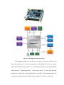
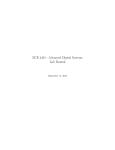
The QSYS diagram with all of the required components is shown in Figure 2.8. The
50 MHz oscillator on the DE0-Nano board was used for the system clock. A NIOS II/s
processor was created with a 4 Kbyte instruction cache. The reset vector was pointed to
the serial flash memory.
8
On-chip memory of type RAM, 32 wide, with a total memory size of 32,768 bytes
was added next. The JTAG UART was used to debug the system while it was connected
to a PC via the USB port. It was also used to program the device before the final version
was uploaded to the EPCS flash memory.
Two separate UARTs needed to be created; one for the cell phone, and one for the
GPS receiver. The cell phone UART was created with no parity bit, 8 data bits, 1 stop bit,
and a baud rate of 4800 bps. The GPS UART was created with no parity bit, 8 data bits, 1
stop bit, and a baud rate of 38400 bps. The UARTs were manipulated by reading the
status register and determining if there were any errors present or if there was data to be
read in the receive register. If data needed to be sent over the UART the transmit data
register was used. More details about the manipulation of the UARTs and their registers
will be explained in Section 4.
9
Figure 2.8: QSYS Diagram of System
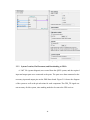
The pushbutton that is needed to initiate the sending of the SMS text message was
added via the PIO peripheral. Only one button was needed, so an input with a width of
one was implemented. The PIO was set up to generate an interrupt when a rising edge of
the signal was detected. These settings are shown in the PIO set-up screen in Figure 2.9.
Finally, the flash controller was added to the system, which enabled the NIOS II
system to access the EPCS serial configuration device which is connected to the FPGA.
10
Figure 2.9: PIO Interrupt Setup
2.3.2
System Creation, Pin Placement, and Downloading to FPGA
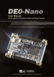
A “.bdf” file (system diagram) was created from the QSYS system, and the required
input and output ports were connected to the ports. The ports were then connected to the
necessary input and output pins on the DE0-Nano board. Figure 2.10 shows the diagram
of the system as well as the pin selections for each component. The GPS_TX signal was
not necessary for this system, since nothing needed to be sent to the GPS receiver.
11
Figure 2.10: System Diagram and Pin Placement
The system was then compiled and the sof programming file generated. Quartus’
Programmer tool was used to download the system file to the FPGA, completing the
process.
12
III.
PROTOCOLS AND STANDARDS
This section will explain the different standards and protocols used to create the
system. The protocols and standards that were used to construct the system were: the
Hayes Command Set, the RS-232 Serial Standard, and GPS.
3.1
Hayes Command Set
The Hayes command set is a command language that was developed in 1981 for the
Hayes Smartmodem 300 baud modem. It consisted of short character strings that when
sent to the modem caused it to perform some of the standard operations, such as dialing,
hanging up, etc. This command set was eventually implemented in some degree in many
dial-up modems. Hayes commands were started by sending AT, or attention. As a result,
these commands came to be known as AT commands.
Eventually, a set of technical specifications was created for controlling a GSM (Global
System for Mobile Communications, which is a standard to describe protocols for 2G
cellular networks) phone or modem. One specification dealt with the AT commands to
control a GSM phone or modem that must be incorporated into the unit [12], and another
dealt with the AT commands to handle the SMS features of GSM [13].
The syntax of AT commands is very straightforward. Each command begins with
“AT” and ends with a carriage return, which signifies to the device that the command is
over and to execute it. Multiple commands can be sent in the same line, but only the first
one should have AT as a prefix. A semicolon (;) is used to separate commands in the
same line. To input a string, the text is enclosed with double quotes [14]. Finally, after the
command has been successfully executed, the device will respond with an OK, which is
preceded and followed by both a carriage return and line feed.
13
Five separate AT commands were utilized for this project. They, along with a brief
description and example, are shown below in Table 3.1. The AT commands were used to
wake up the phone, send the text message, and then delete the message from the phone’s
memory.
Table 3.1: AT Commands Used in Project
Command
Function
AT
Tests Connection
AT+CMGF
Select Message Format
AT+CMG
W
Write Message to
Memory
AT+CMSS
Send Message from
Storage
AT+CMGD
Delete Message from
Storage
3.2
Explanation of
Command
Returns “OK” if
AT
connection works.
Sets the operating
AT+CMGF=1
mode to SMS text
mode.
Starts a message
AT+CMGW=\”+15554445 that will be sent
555\”
to the phone
number indicated.
Send message in
AT+CMSS=1
storage location
1.
Deletes message
AT+CMGD=1
in storage
location 1.
Example Command
RS-232 Serial Standard
RS-232 is a standard for the serial communication transmission of data [15]. The
standard defines the characteristics of the signals being sent between data terminal
equipment and data circuit-terminating equipment (examples are a computer terminal and
modem, respectively), such as their timing, electrical characteristics, and their meaning.
RS-232 serial ports used to be included as a part of personal computers, which were
used to connect a variety of devices like modems, printers, and power supplies. Some of
the detriments of RS-232, such as the large connectors, were factors that led to the
creation of the Universal Serial Bus (USB) which has taken over from RS-232 in many of
14
its applications. However, because RS232 provides high noise margin, it is still being
used in some applications where the distance between two devices is over ten feet.
RS-232 data is sent serially over a single transmission line. The data format consists
of a start bit, a number of data bits, a parity bit, and finally a stop bit. The parity bit can
be used to check the “correctness” of the received data and is optional. The RS-232 signal
for sending “AT” is depicted in Figure 3.1. “A” in hexadecimal is 0x41, while “T” is
0x54. The data is sent asynchronously, with the least significant bit being sent first. The
voltage levels as defined in the RS-232 standard range are as shown in Table 3.2.
Figure 3.1: Sample RS-232 Signal Waveform
Table 3.2: RS-232 Voltage and Logic Levels
Voltage Level
+3 to +15
-3 to -15
Logical State
0
1
The RS232 UART core for a NIOS II processor was utilized to transfer data between
the FPGA and cell phone, as well as between the FPGA and GPS receiver for this project.
3.3
GPS
The Global Positioning System (GPS) is a navigation system that relies on a series of
space-based satellites to provide location and time information [16]. It was developed in
1973 by the United States Department of Defense, which also still maintains it. Twentyfour satellites, minimum, are in orbit around Earth at any given time. Anyone, military or
civilian, with a GPS receiver can access the system.
15
GPS data is received in sentences. In the NMEA format, the sentences all begin with
“$GPXXX”, with the final three letters indicating what kind of data is included in the
sentence. For example, $GPGLL contains the geographic position, latitude, and longitude
of the receiver. A decoded example of a $GPGLL sentence is shown in Table 3.3.
Table 3.3: Decoded Sample NMEA $GPGLL Message
$GPGLL,3441.45,N,11809.12,W,132655,A
3441.45,N
Latitude 34º 41.45 min North
11809.12,W Longitude 118º 9.12 min West
132655
Data taken at 13:26:55 UTC
A
Data valid
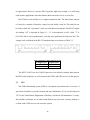
The GPS receiver used for this project output the GPS data in a proprietary format,
not NMEA. The format of the message is shown in Figure 3.1 [17]. Only one message
was needed for this project, which had the fields depicted in Table 3.4.
Figure 3.2: UBX Message Structure
Table 3.4: Message Characteristics Required for Latitude and Longitude
Sync Char 1
0xB5
Sync Char 2
0x62
Class
0x01
ID
0x02
The class field 0x01 indicates a message that contains navigation data, and an ID of
0x02 means that the message has geodetic position data (latitude, longitude, altitude).
The message holds 28 bytes worth of data, with latitude and longitude each being 4 bytes
long.
16
IV.
SOFTWARE
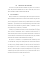
This section will discuss the C code that was written to support the project. It will
cover the structure and flow of the code.
Figure 4.1 presents a flowchart of how the program works. The program reads the
GPS receiver each time through the program and checks to see if an error has occurred. If
it has, the error is cleared. Otherwise, the program checks to see if message being read is
the correct one. It goes through a state machine for each step of the message, before
finally calculating the latitude and longitude.
Figure 4.1: Program Flowchart
17
When the button is pressed, it generates an interrupt. In the interrupt service routine, a
value is set to 0. The main program checks that value, and if it is set to 0, it converts the
latitudes and longitudes to character strings. This conversion is hard-coded, and is
customized for locations greater than 100º west longitude and in the northern hemisphere.
Since decimals aren’t included in the position coordinates, the conversion places a
decimal after the first three digits and places a negative in front for the number.
Once the latitude and longitude have been converted into a character string, they are
sent to a function that interfaces with the cell phone to send the SMS text with the
location information. A state machine is used to send each AT command while checking
to see if an error has occurred. After all the AT commands (and thus the SMS text
messages) have been sent, the function ends and the main program continues, which
waits for another button press to send another SMS text message.
The GPS receiver is read by checking the UART registers that it is connected to. The
cell phone works the same way. The UART Core Register map is provided in Figure 4.2
[18]. The status register is read first, and if the 8th bit (error bit) is a ‘1’, an error has
occurred. The 8th bit checks is a logical OR of the other error bits, “toe” (transmit overrun
error), “roe” (receive overrun error), “brk” (break detect), “fe” (framing error), and “pe”
(parity error). If an error has occurred, it is cleared by simply writing to the status
register.
18
Figure 4.2: UART Register Map
For the GPS, if an error has not occurred, the rxdata register is read and an operation
is performed based on the state machine’s current state. Eventually, the latitude and
longitude are read. These coordinates, however, are in two’s complement (a function of
the UBX format), and must be converted so that they can be shown in the expected
coordinate format (Degrees Minutes Seconds)
The cell phone operation involves both the rxdata and txdata registers. The
program checks to see if there is anything in the “rrdy” (receive char ready) bit after
checking the status register for an error. If there is, the rxdata register is read and
compared to what should be received. The final bytes received for the messages should
read “OK”, which signifies that the command sent to the phone has been received and
executed. The only exception is after sending the AT+CMGW command, which returns a
“>” character.
After checking the “rrdy” bit, the “trdy” (transmit ready) bit is tested. If it is a ‘1’,
then a new character is ready to be transmitted. A state machine is used to transmit each
character of a given command. After the entire command has been sent, a pause occurs so
that the cell phone has enough time to execute it without being disturbed.
19
V.
RESULTS
Screenshots of the JTAG UART output are shown in Figures 13 and 14. These were
captured when the final code had been written, but the program had not yet been loaded
into the flash memory of the DE0-Nano board. The board, which was powered via a USB
cable, was able to print to the monitor of the computer which it was attached to. Figure
5.1 shows what the program was outputting when no button was pressed. The latitude and
longitude were constantly being read from the GPS receiver and displayed. This provided
a check that the GPS receiver was functioning correctly.
Figure 5.1: JTAG UART Output, GPS Coordinates
Figure 5.2 shows the output after the button has been pressed and the coordinates are
in the middle of being sent. After each AT command was transmitted, a message was
printed to the screen. The response from the phone was also printed, ensuring that the
phone was responding correctly.
20
Figure 5.2: JTAG UART Output, AT Commands
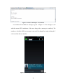
A screenshot of the SMS text message is given in Figure 5.3. The message is sent
with the current GPS coordinates of the user along with a message to send help. The
number to which the SMS text message is sent could be changed by simply editing the C
code to include the new number.
Figure 5.3: Screen Capture of SMS Text Message Received
21
While testing the design, a couple of anomalies did occur and had to be resolved.
First, it did not seem that the phone was receiving the AT commands that were sent to it.
It was eventually determined that the phone was not being given enough time to execute
the command before another one was sent. By adding a pause after a command was sent
and checking the receive register for the appropriate response, this issue was solved.
Another complication involved concatenating several character strings together, which
was needed to send the actual distress message. A thorough search of the internet found a
C command (snprintf) that accomplished the task. A third obstacle was ensuring that the
button press to send the message was read by the board. Initially, the button was polled
each time through the program, which seemed to work satisfactorily. However, when the
program was loaded into the flash memory of the DE0-Nano board, the button press was
never confirmed. To correct this problem, an interrupt was instituted. The interrupt was
able to correctly ascertain when a button press occurred. The final source of contention
also occurred when the program was loaded into the flash memory. The message sent
while the program was running from flash memory did not send the negative sign in front
of the longitude variable. The code which was written to place the decimal in the
longitude coordinate therefore placed the decimal in the wrong spot. Instead of sending a
longitude value of -118.1602, for example, a value of 1181.602 was sent. The code was
re-written to account for this.
22
VI.
CONCLUSION
This project demonstrated the design and construction of a system that could send a
distress signal via SMS text message with a user’s current latitude and longitude
coordinates. An FPGA board, GSM cell phone, and GPS receiver were utilized to create
and send the signal. The system was able to successfully send an SMS text message with
the coordinates to another cell phone each time the button on the DE0-Nano board was
pressed.
It was determined at the conclusion of testing that there were areas where the
reliability and performance of the system could be improved. For example, an actual
GSM modem could be used instead of a GSM cell phone. This would potentially be
easier to communicate with than the cell phone used in this project, since the modem
could have a serial output readily available instead of having to go through the headphone
jack as was done here.
A second area of improvement would be miniaturization. There are many parts of the
DE0-Nano board that weren’t used in this project and simply took up space. The same is
true of the other components as well. Miniaturization would enable the system to be
easily carried so that it could be accessed quickly if needed. An additional enhancement
would be adding a 406 MHz distress radio beacon which would send a distress signal to
orbiting satellites as well.
In conclusion, the system was able to fulfill its objective of sending a distress signal
via SMS text message with GPS coordinates. While there is potential of optimization, the
system as-is performs satisfactorily.
23
REFERENCES
[1]
H. Makino, I. Ishii, M. Nakashizuka, “Development of Navigation System for the
Blind Using GPS and Mobile Phone Combination,” in Proceedings of the 18th
Annual International Conference of the IEEE Engineering in Medicine and
Biology Society (Volume 2), 1996, p. 506-507.
[2]
B. R. Prudhvi, R. Bagani, “Silicon Eyes: GPS-GSM based Navigation Assistant
for Visually Impaired using Capacitive Touch Braille Keypad and Smart SMS
Facility,” in World Congress on Computer and Information Technology, 2013, p.
1-3.
[3]
A. Mhapeskar, P. Kulkarni, U. Nagarsekar, D. Kalbande, “Voice Enabled
Android Application for Vehicular Complaint System Using GPS and GSM-SMS
Technology,” in World Congress on Information and Communication
Technologies, 2012, p. 520-524.
[4]
S.T.S Thong, T.H. Chua, T.A. Rahman, “Intelligent Fleet Management System
with Concurrent GPS and GSM Real-Time Positioning Technology,” in 7th
International Conference on ITS Telecommunications, 2007, p. 1-6.
[5]
I. Almomani, N. Alkhalil, E. Ahmad, R. Jodeh, “Ubiquitous GPS Vehicle
Tracking and Management System,” in IEEE Jordan Conference on Applied
Electrical Engineering and Computing Technologies, 2011, p. 1-6.
[6]
R. Anderson, A. Poon, C. Lustig, W. Brunette, G. Borriello, B. Kolko, “Building
a Transportation Information System Using Only GPS and Basic SMS
Infrastructure,” in International Conference on Information and Communication
Technologies and Development, 2009, p. 233-242.
[7]
R. Moloo, V. Digumber, “Low-Cost Mobile GPS Tracking Solution,” in
International Conference on Business Computing and Global Informatization,
2011, p. 516-519.
[8]
M. Shirali-Shahreza, “Emergency SMS,” in SICE-ICASE International Joint
Conference, 2006, p. 1139-1142.
[9]
DE0-Nano User Manual, Terasic Technologies, 2012
[10]
“NEO-6 u-blox 6 GPS Modules Data Sheet”, u-blox AG, Thalwil, Switzerland,
2011.
[11]
(2013)
M@’s
Projects.
[Online].
Available:
http://sheffiel.blogspot.com/2011/02/remote-car-starter-controlling-motorola.html
24
[12]
3rd Generation Partnership Project; Technical Specification Group Core
Network and Terminals; AT command set for User Equipment (UE) (Release 12),
3GPP TS 27.007, 2012-2013.
[13]
3rd Generation Partnership Project; Technical Specification Group Core
Network and Terminals; Use of Data Terminal Equipment – Data Circuit
terminating Equipment (DTE-DCE) interface for Short Message Service (SMS)
and Cell Broadcast Service (CBS) (Release 11), 3GPP TS 27.005, 2011-2012.
[14]
(2013) Short Message Service/SMS
http://www.developershome.com/sms/
[15]
Interface Between Data Terminal Equipment and Data Circuit-Terminating
Equipment Employing Serial Binary Data Interchange, EIA/TIA-232-F, 1997
[16]
(2013) Navigation Programs – Global Positioning System. [Online]. Available:
http://www.faa.gov/about/office_org/headquarters_offices/ato/service_units/techo
ps/navservices/gnss/gps/
Tutorial.
[Online].
Available:
[17] “u-blox 6 Receiver Description Including Protocol Specification”, u-blox AG,
Thalwil, Switzerland, 2013.
[18]
“NIOS UART”, Embedded Peripherals IP User Guide, Altera, San Jose, CA,
2003
25
APPENDIX - C Program Code
//Sending SMS Text Message with GPS Coordinates
//Created by Alexander Hale, March 15 2014
//Hardware:
//
NIOS II/s Processor
//
Reset Vector Memory: EPCS Flash Controller
//
Exception Vector Memory: On-chip memory
//
50 MHz Clock
//
32 Kb On-chip Memory (RAM), 32 wide
//
JTAG UART, 64 byte read and write buffer depth
//
System ID Peripheral
//
UART_0 – Used for Cell Phone Communication (Connected to Motorola C168i
//
cell phone)
//
No parity, 8 data bits, 1 stop bit, 4800 bps
//
GPS_UART – Used for GPS Receiver Communication (Connected to u-blox
//
NEO-6M GPS receiver)
//
No parity, 8 data bits, 1 stop bit, 38400 bps
//
EPCS Serial Flash Controller
//
LIGHTS – Used for awareness on sending SMS text message
//
8 wide Output PIO
//
BUTTON_PIO - Used to Send SMS Text message
//
1 wide Input PIO
//Algorithm:
//
Program will take information from GPS_UART and parse it to determine current
//
Latitude and Longitude. This process is repeated until a button press occurs. An
//
interrupt request is generated upon a button press which sets a variable to ‘0’. The
//
main function checks this variable, and upon seeing a ‘0’, will convert the
//
Latitude and Longitude (which are unsigned long numbers) to strings and insert a
//
decimal in the proper places. The character strings of Latitude and Longitude are
//
sent to the sendphonemsg() function, which uses UART_0 to send an SMS text
//
message using AT commands. After the SMS Text message is sent, the program
//
returns to the main function, where Latitude and Longitude are calculated until
//
another button press.
///////////////////////////////////////////////////////////////////////////////////////////////////////////////////////
#include "altera_avalon_pio_regs.h"
#include "alt_types.h"
#include "sys/alt_irq.h"
#include "system.h"
#include <unistd.h>
#include <stdio.h>
#include <string.h>
26
#include <io.h>
volatile int edge_capture;
int button_value=1;
//Function: handle_BUTTON_PIO_IRQ
//
Interrupt Service Routine
//
Interrupt Source: BUTTON_PIO
//
Parameters Passed: Interrupt Controller Identifier
//
Parameters Returned: None
//
Usage: Called whenever push button is pressed, Used to tell program to send SMS
//
text message with current GPS coordinates
void handle_BUTTON_PIO_IRQ(void* context, alt_u32 id)
{
volatile int *edge_capture_ptr = (volatile int*) context;
*edge_capture_ptr = IORD_ALTERA_AVALON_PIO_EDGE_CAP
(BUTTON_PIO_BASE);
IOWR_ALTERA_AVALON_PIO_EDGE_CAP(BUTTON_PIO_BASE, 0);
IOWR_ALTERA_AVALON_PIO_IRQ_MASK(BUTTON_PIO_BASE, 0x1);
button_value = 0; //Used in main program to indicate button press and send the
// SMS text message
IOWR(LIGHTS_BASE,0,0xFF); //Turn on LEDs to indicate system reads button
//press
}
//Function: INIT_BUTTON_PIO
//
Initialization Function
//
Parameters Passed: None
//
Parameters Returned: None
//
Usage: Called at beginning of main() to initialize and register push button
//
interrupt
void INIT_BUTTON_PIO()
{
void* edge_capture_ptr = (void*) &edge_capture;
IOWR_ALTERA_AVALON_PIO_IRQ_MASK(BUTTON_PIO_BASE, 0x1);
IOWR_ALTERA_AVALON_PIO_EDGE_CAP(BUTTON_PIO_BASE, 0x0);
alt_irq_register(BUTTON_PIO_IRQ,edge_capture_ptr,
handle_BUTTON_PIO_IRQ);
}
//Function: sendphonemsg()
//
Send SMS Text Message Function
//
Parameters Passed: Latitude and Longitude character strings
//
Parameters Returned: None
//
Usage: Called once a button is pressed, this function uses AT commands to send a
//
SMS text message via the UART_0 UART and the cell phone connected to it
27
void sendphonemsg(char lat[],char lon[]) //Function is used to send the SMS text
//message
{
unsigned long b=0,a=0;
unsigned long read,write;
int i=0,j=0;
int go=1;
int state=1;
int ok = 1;
char setup[] = "AT\r\n";
char format[] = "AT+CMGF=1\r\n";
char message[]="AT+CMGW=\"+16619749209\"\r\n";
char str1[]="Send help ASAP. I am at Lat: ";
char str2[]=", Lon: ";
char str3[]="\x1a";
char text[144];
snprintf(text,sizeof text,"%s%s%s%s%s",str1,lat,str2,lon,str3);
char send[] = "AT+CMSS=1\r\n";
char del[]="AT+CMGD=1\r\n";
char response[144];
int respind=0;
int sending=1;
unsigned long ERR;
//b= IORD(UART_0_BASE,0);
while(sending==1)
{
b = IORD(UART_0_BASE,2); //Check Status Register
////printf("b: %lx\n",b);
read = b >> 7;
write = b >> 6;
ERR = b >> 8;
j = j+1;
if(j == 2500000) //Pause to ensure enough time has elapsed before sending
//next message
{
go = 1;
j = 0;
}
if(ERR & 1) //Check for an error. If there, clear it
{
IOWR(UART_0_BASE,2,0x00000000);
//printf("b : %4lx : reset\n",b);
28
j = 0;
i=0;
}
else //If there wasn’t an error, check to see if you can read/write
{
if(read & 1) //Is there something waiting to be read?
{
a = IORD(UART_0_BASE,0); //read value in rxdata
//printf("read: %c\n",a);
response[respind]=(char)a;
respind++;
switch(ok)
//Have you gotten an OK or > back from the phone?
{
case 1:
if(a == 0x4F) // O
ok = 2;
else
{
if(a == 0x3E) // >
{
ok = 1;
state=state+1; //> received, send next AT
// command
//printf("%s---new state:%d\n",
response,state);
respind=0;
//clear character string
memset(&response[0],0,sizeof(response));
}
else
ok = 1;
}
break;
case 2:
if(a == 0x4B) //K
{
ok = 1;
state = state + 1; //OK received, send next AT
//command
//printf("%s---new state:%d\n",response,state);
respind=0;
//clear character string
memset(&response[0],0,sizeof(response));
}
29
else ok = 1;
break;
}
}
if((write & 1) && (go == 1))
{
IOWR(LIGHTS_BASE,0,state); //LEDs indicate what state
//you're in
switch(state)
{
case 1: //AT command
if(i < sizeof(setup)) //Send command character by character
{
IOWR(UART_0_BASE,1,setup[i]); //write to
// txdata
i = i+1;
}
else //entire command sent
{
//printf("wrote: %s\n",setup);
go = 0;
i = 0;
}Send
break;
case 2: //AT+CMGF command
if(i < sizeof(format))
{
IOWR(UART_0_BASE,1,format[i]);
i = i+1;
}
else
{
//printf("wrote: %s\n",format);
go = 0;
i = 0;
}
break;
case 3: //AT+CMGW command
if(i < sizeof(message))
{
IOWR(UART_0_BASE,1,message[i]);
i = i+1;
}
30
else
{
//printf("wrote: %s\n",message);
go = 0;
i = 0;
}
break;
case 4: //Text in the SMS message
if(i < sizeof(text))
{
IOWR(UART_0_BASE,1,text[i]);
i = i+1;
}
else
{
////printf("wrote: %s\n",text);
go = 0;
i = 0;
}
break;
case 5: //AT+CMSS command
if(i<sizeof(send))
{
IOWR(UART_0_BASE,1,send[i]);
i=i+1;
}
else
{
//printf("wrote: %s\n",send);
go=0;
i=0;
}
break;
case 6: //AT+CMGD command
if(i<sizeof(del))
{
IOWR(UART_0_BASE,1,del[i]);
i=i+1;
}
else
{
//printf("wrote: %s\n",del);
31
go=0;
i=0;
}
break;
case 7: //All AT commands sent, SMS text message sent
sending=0;
go=0;
i=0;
break;
}
}
}
}
}
//Function: main()
//
Starting and Main Function of Program
//
Parameters Passed: None
//
Parameters Returned: None
//
Usage: Main program initializes variables and interrupt, then loops indefinitely.
//
Calculates Latitude and Longitude coordinates and checks to see if the
//
Interrupt Service Routine has changed the button_value variable to ‘0’,
//
signifying a button press. If a button is pressed, Latitude and Longitude
//
are converted to character strings and sendphonemsg() is called.
int main(void) //Main program
{
volatile int * sw_ptr=(int *) BUTTON_PIO_BASE;
//int button_value;
INIT_BUTTON_PIO();
char lat[15];
char lon[15];
unsigned long longitude;
unsigned long latitude;
unsigned int a;
int b,i=0,j;
int state = 1;
unsigned int read;
unsigned int ROE;
unsigned int EOP;
unsigned int BRK;
unsigned int ERR;
unsigned int data[50];
unsigned int msg_length=0;
unsigned int msg_type;
32
unsigned int ck_a,ck_b;
unsigned long altitude;
IOWR(GPS_UART_BASE,2,0x00000000); //Clear status register just in case
// there was something there
// previously
char lat1a[5];
char lon1[15];
char dec[]="\x2e";
char neg[]="\x2d";
char lat1b[13];
char lon1b[13];
char lat2[16];
char lon2[16];
while(1) //Once inside this loop, program continues indefinitely
{
//button_value=*(sw_ptr);
//IOWR(LIGHTS_BASE,0,button_value);
if(button_value==0) //Button has been pressed, prepare to send SMS
//text message
{
button_value = 1; //Reset button press
int n=sprintf(lat,"%lu",latitude); //convert the latitude and
//longitude to character strings
int m=sprintf(lon,"%d",longitude);
for (i=0;i<sizeof(lat)-2;i++)
{
lat1b[i]=lat[i+2];
}
//Add decimal to Latitude
snprintf(lat2,sizeof lat2,"%c%c%s%s",lat[0],lat[1],dec,lat1b);
for (i=0;i<sizeof(lon)-3;i++)
{
lon1b[i]=lon[i+3];
}
//Add negative and decimal to Longitude
snprintf(lon2,sizeof lon2,"%s%c%c%c%s%s",
neg,lon[0],lon[1],lon[2],dec,lon1b
sendphonemsg(lat2,lon2); //Function call, send the SMS
// text message
33
//printf("Lat: %s, Lon: %s\n",lat2,lon2);
//printf("Waiting to send again...\n");
}
b = IORD(GPS_UART_BASE,2); //Check status register of GPS
//printf("%x",b);
//txready = b >> 6;
read = b >> 7;
ROE = b >> 3;
EOP = b >> 12;
BRK = b >> 2;
ERR = b >> 8;
if(ERR & 1) //If error is there, clear it
{
IOWR(GPS_UART_BASE,2,0x00000000);
//printf("b : %4x : reset\n",b);
}
else //If there wasn’t an error, check to see if you can read/write
{
if(read & 1) //Is something waiting to be read?
{
a = IORD(GPS_UART_BASE,0); //Read value in rxdata
switch(state)
{
case 1:
if(a == 0xB5) //Check for correct NAV message
{
state = 2;
i = 0;
}
else state = 1;
break;
case 2:
if(a == 0x62)
{
state = 3;
}
else state = 1;
break;
case 3:
if(a == 0x01)
{
state = 4;
34
}
else state = 1;
break;
case 4:
if(a == 0x02)
{
msg_type = 1;
state = 5;
}
else state = 1;
break;
case 5: //length1
msg_length = a;
state = 6;
break;
//Get length of parameter
case 6: //length2
msg_length = msg_length + (a << 8);
state = 7;
break;
case 7: //payload
data[i] = a;
i = i+1;
if(i == msg_length)
break;
state = 8;
case 8: //checksum1
ck_a = a;
state = 9;
break;
case 9: //checksum2
ck_b = a;
state = 1;
//Calculate Longitude and Latitude
if(longitude > 0x80000000)
{
longitude = (data[4] + (data[5] << 8) +
(data[6] << 16) + (data[7] <<
24)) - 0xFFFFFFFF + 0x01;
}
else
{
35
longitude = 0xFFFFFFFF - (data[4] +
(data[5] << 8) + (data[6] << 16)
+ (data[7] << 24)) + 0x01;
}
//printf("Longitude : %d, ",longitude);
latitude = (data[8] + (data[9] << 8) + (data[10] <<
16) + (data[11] << 24));
//printf("Latitude : %lu, ",latitude);
break;
}
}
}
}
return 0;
}
36