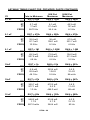
1
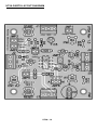
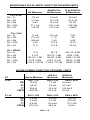
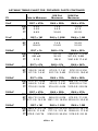
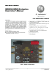
25. Install JMP1, another2 pin header. 26. Install JMP7, you guessed it another 2 pin header. 27. Install JMP6, a 3 pin header. 28. Install JMP5, finally the last 2 pin header. 28. Install D4, this diode is marked 1N4002. This part has a black body with one silver or white stripe on one end. It is a stand up diode. Bend the lead closest to the stripe over so that it comes back across the diode and is in parallel with the other lead. Match this (stripe end) lead to the circuit board pad closest to the white stripe on the board’s silkscreen. The lead attached to the black body goes through the hole with the silkscreen circle. 30. Install D3, another 1N4002 diode (marked 1N4002). Install this diode in the same manor as D4. 31. Install C3, a 10uF electrolytic capacitor (marked 10uF). Electrolytic capacitors have a right and wrong way to be installed. Usually, these capacitors have a wide stripe which indicates their polarity. Most of the time this stripe indicates the negative lead. This can be verified by looking for the (-) sign in the stripe. On rare occasions this stripe with have a (+) sign indicating a positive polarity. The PC board or Parts Layout Diagram will show the positive side of the capacitor's installation hole. Be sure to place the ( + ) capacitor lead into the PC board ( + ) hole and the ( - ) lead into the ( - ) hole. Observe correct polarity when installing all electrolytic capacitors. 32. Install J2, a three terminal-terminal block. The wire openings must face outboard. Make sure the terminal block is square and flush to the circuit board. 33. Install J1, another three terminal-terminal block. Install it with the same precautions you did J2. 34. Install J4, a three terminal-terminal block. 35. Install J5, a three terminal-terminal block. 36. Install J3, the last three terminal-terminal block. You will probably notice five parts are still missing from your board and you have more than five parts left. A this point you will need to figure out what part values you need to install for your first application. See the theory of operation section for calculations or the charts that follow at the end of this section for a component values. UT5A 17