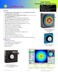
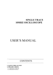
1
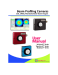
Digital CCD Beam Profiling – 1.4 MegaPixel 14-bit ADC
WinCamD – Everything that you liked about WinCam-PCI made better, smaller & faster & digital.
•
•
•
•
•
•
•
•
•
14-bit ADC is standard.
48 dB optical dynamic range with
software slider electronic shutter,
16 µs to 1 s, 16 µs steps.
Accepts Pulsed laser TTL trigger.
Variable capture region,
1 x 1 to 1360(H) x 1024(V) pixels
Window-free CCDs – no fringes.
For Windows 98, Me, NT, 2000.
No IRQ's. < Half-size PCI card.
UV & IR system options.
Notebook PC option.
Actual imaged areas: 300 - 1150 nm Silicon CCDs:
•
WinCamD
6.3(H) x 4.8(V) mm (1/2” format) progressive scan CCD with 1.4 MPixels, 4.65 µm
square.
•
WinCamD/IR IR version for Telecom C & L bands
•
TaperCamD
14.4(H) x 10.8(V) mm with 2.27:1 fibre optic taper* on 1M4 CCD
•
TaperCamD20/15
19.6(H) x 14.8(V) mm with 3.1:1 fibre optic taper* on 1M4 CCD
* <+/- 2% barrel/pincushion distortion
WinCamD is the digital beam profiling camera you have been waiting for:
•
•
•
•
•
•
•
•
14-bit ADC standard in the head – always more than enough (See Page 4 to understand how this helps)
TTL input trigger for pulsed lasers
Even more compact camera head
Even higher electronic shutter dynamic range, 6x10 4 :1
IRQ-free operation under Windows 98, Me, NT, 2000
Digital head-to-card cable for low EMI pick-up
Large area 14 x 10 mm TaperCam option
Flexible 6-pin FireWire-style serial cable
•
•
•
•
•
XY profiles and centroids, Gaussian and Top Hat fits.
Ellipticity: Auto-orientation, Major, Minor & Mean Dias.
Background capture and subtraction
User-set Spatial and Intensity Zoom plus smoothing filter
Image Averaging, 1 to continuous.
•
•
3 year warranty
Free software upgrades
[email protected]
z
www.lambdaphoto.co.uk
WinCamD Product Specifications [Product specifications are subject to change without notice]
ITEM
Measurable Sources
SPECIFICATION
CW beams, pulsed sources. 1Hz to ~50 kHz with single pulse isolation
User configurable synchronous, asynchronous & variable delay
trigger options. Software programmable trigger input, +ve or –ve
edge, 50 Ω or 1 k
Measured Beam Powers
Wavelength Range:
WinCamD
WinCamD/IR
Third party cameras (CCIR, RS170)
Electronic Dynamic Range
CW beams
Pulsed, Pulse-width <5 µs
Pulse-width >5 µs
Manual Beam Attenuation,
All beams:
Options:
ADC converter
Imaged Beam Dimensions
WinCamD
TaperCamD
Measurement Accuracy
Measured & Displayed Profile
Parameters
Beam Diameter:
Beam Fit:
Ellipticity:
Centroid Position:
Filtered profile:
Displayed Profiles
Displayed Plots
See the Maximum Power Graph and Notes, below.
e.g. ~2µW to 100mW, for a 1mm dia. Gaussian beam @633 nm (ND4 filter
on)
350 to 1150 nm [Works down to 190 nm but degrades over time.]
1480 to 1680 nm
Startech UV imaging plate cameras for <350 nm are available
UV, NIR and IR X-ray to 20 µm.
48 dB (60,000:1) for ~30 dB SNR, using variable electronic shutter)
+ 7.5 dB (5,7:1) for ~30dB SNR, using CCD gain control only.
7.5 dB (5,7:1) for ~30 dB SNR, using CCD gain control only.
7.5 dB + [Pulsewidth /5µs]:1
Provided ND 4.0 C-mount Neutral Density filters.
[ND 4.0 at 546 nm, higher in blue and UV, lower in near IR.]
EAM-2 4-wheel stepped variable attenuator, 0 to 90 dB
CUB and CUB-UV 3 to 10 % beam samplers for high power beams
1% and 0.05% Holographic Beam Samplers
14-bit ADC in head. All models.
For the best results, beam diameter should not exceed half the array
dimensions.
Directly: 50 µm diameter to 6.32 x 4.76 mm 1360 x 1024 pixels, 4.65 µm
square
Directly: 120 µm diameter to 14.2 x 10.7 mm Pixels 10.5 µm square
2.25:1 fibre optic taper on 1M4 CCD
Smaller, or indefinitely larger beam diameters can be imaged.
<1µm processing resolution
Diameter at user defined Clip level
Gaussian & Second Moment beam diameters
Equivalent diameter above a user defined Clip level
Equivalent Slit and Knife Edge diameters
Gaussian profile fit & % fit
Top Hat profile fit & % fit
Equivalent Slit profile
Major, Minor & Mean diameters. Auto-orientation of axes.
Relative and absolute
Intensity Weighted Centroid and Geometric Centre
Beam Wander Display and Statistics
0 to 1 % triangular running average to smooth noisy profiles
X & Y with superimposed Gaussian or Top Hat fit. Zoom x1 to x10
User set curves showing % acceptable deviation from Gaussian
2-D & 3-D plots (10,16 or 256 colours or grey). Colour contour plot at 10%
intervals
Zoom x1 to x32
White perimeter circle at Centroid
[email protected]
z
www.lambdaphoto.co.uk
Displayed Target
Processing Options
Update Rate
Data Analysis
Pass/Fail display
Averaging
Log data and statistics
Power Measurement
Source to Camera Distance
Dimensions
Camera Head (See drawing)
Mounting
Weight, Camera Head
Recommended Minimum PC
Requirements:
(Mac version is not available)
4 pixel black spot at beam Peak
Double bulls-eye centred on crosshairs or CCD chip (on/off option)
Image averaging, 1 to continuous
Background Capture and Subtraction
User set rectangular or elliptical Capture region
*.job files save all WinCam custom settings for particular test configurations
5 Hz maximum for full frame, full screen on 1M4 chip (no interlacing)
20 Hz for 512 x 512 pixels
Higher rate for smaller capture regions. E.g. 175 Hz max for 1 line readout.
On-screen, in selectable Pass/Fail colours. Ideal for QA & Production.
Beam dimension running average up to 50 samples
Min., Max., Mean, Standard Deviation. Up to 4096 samples
Units of mW or user choice (relative to a reference measurement input)
Fluence, within user defined area
~14 mm optical distance from front of ND filter to CCD chip.
Across axis width x Height x Along axis depth [inc. ND filter, 5.7 mm (0.23”)
thick]
115* x 61 x 22 mm (4.5 x 2.4 x 1.07 inches) *~150 mm (~6”) with cable
connected.
Universal mounting block ¼-20 and M6 threaded and clearance mounting
holes
230 gm (0.5 lb); 310 gm (0.7 lb) with Mounting block
500 MHz Pentium III running Windows 98, Me, NT, 2000 or XP; 128 MB
RAM; PCI Slot;
10 MB Hard Drive space; 1024 x 768 monitor.
Notebook PC Third party adaptor available.
Maximum Power Graph
The graph allows you to simply determine the approximate maximum
optical power that WinCamD can measure without additional
attenuation. In both cases the Saturation Limit assumes:
•
A 1/e2 (13.5% clip level) beam diameter of 1mm
•
The provided ND 4.0 filter in place
•
The electronic shutter set at 16µs, its lowest value
•
The CCD amplifier gain set at 1, its lowest value
•
The total power does not exceed 1W total
CW Laser: The upper (green) line is the Limit for CW Lasers in mW.
E.g. At 633nm the Saturation Limit for a '1 mm HeNe' is ~150 mW.
For a 0.1mm diameter beam the limit is 102 less at ~1.5mW
For a 3mm diameter beam the limit would be 32 greater at ~1.35 W,
but since this exceeds the 1W total, the limit would be 1W.
Pulsed Lasers: The lower (red) line is the Limit for Pulsed Lasers in µJ of
energy within 16 µs ( the minimum shutter period).
E.g. At 1064 nm the Saturation Limit for a '1 mm Nd:Yag' is ~1 µJ in 16 µs
If the Pulse Repetition Rate is ≤60 kHz this is 1 µJ per pulse.
If the Pulse Repetition Rate is >60 kHz this is <1 µJ per pulse.
For a 0.1 mm diameter beam the limit is 10 2 less at ~0.01 µJ in 16 µs.
For a 3 mm beam the limit rises by 3 2 to 9 µJ per pulse … except that the 1 W limit means that the PRR must not
exceed ~50 kHz.
[email protected]
z
www.lambdaphoto.co.uk
Part Number
WinCamD
TaperCamD
TaperCamD20/15
WinCamD/IR
TaperCamD/IR
WCDBoard
WCamD
TCamD
TCamD20/15
WCamD/I R
TCamD/IR
ND0.5 to ND 4.0
Description
Complete working system comprising WCDBoard + WCamD
Complete working system comprising WCDBoard + TCamD
Complete working system comprising WCDBoard + TCamD20/15
Complete working system comprising WCDBoard + WCamD/IR
Complete working system comprising WCDBoard + TCamD/IR
Software + PCI card + Cable + User manual (Camera not included). Does
not include PC.
Digital CCD Camera: 6.32 x 4.76 mm active area; 4.65 µm square pixels
Digital CCD Camera with FO Taper: 14.2 x 10.7 mm active area; 10.5 µm
square pixels
Digital CCD Camera with FO Taper: 19.6 x 14.4 mm active area; 10.5 µm
square pixels
IR version of WCamD for Telecom C & L bands
IR version of TCamD for Telecom C & L bands
Neutral density filters in ND 0.5 steps in stackable C-mount threaded
holders
The Advantages of 14-bit Analog to Digital Conversion and ‘Digital’ cameras
ADCs. The first CCD beam profilers (in the early 90’s) were relatively noisy. 8-bit (256 level) ADCs could
adequately sample the signal and the noise if the peak signal was close to saturation. As CCD noise & ADC prices
decreased in the late 90’s, some manufacturers offered 10-bit (1024 level) and 12-bit (4096 level) ADC options,
though for a significant price increase.
With WinCamD, the ‘How many ADC bits can I afford?’ dilemma is deleted from the buying equation.
Taking advantage of the latest lower noise Sony CCD chips (10 to 11-bit equivalent noise) and of ADC
price reductions, we provide a 14-bit (16,384 level) ADC on all WinCamD systems. For the customer this
gives ultimate performance at no extra cost. The 14-bit ADC capability may also be interfaced to cooled
CCD analog output cameras.
“Digital” cameras. In WinCamD, the software talks directly to the CCD chip, avoiding the limitations of the
manufacturer’s driver chipset. This enables external trigger, wider shutter speed control and user-defined image
capture regions with higher update rates. Placing the ADC in the head allows a digital link from head to PC card,
insensitive to the EMI (Electro-Magnetic Interference) problems that can plague analog video links in high power
pulsed laser measurements.
[email protected]
z
www.lambdaphoto.co.uk