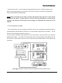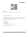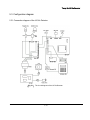
1
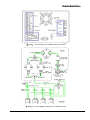
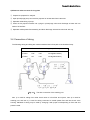
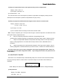
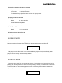
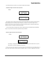
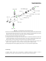
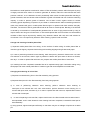
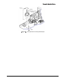
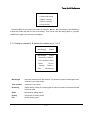
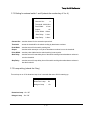
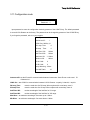
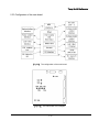
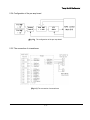
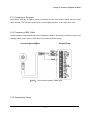
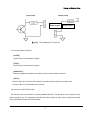
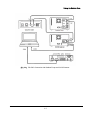
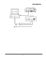
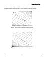
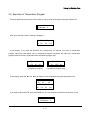
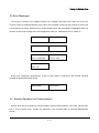
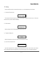
Young Lin UV/Vis Detector
Connect the cell outlet to a line leading to an appropriate waste reservoir. If bubble formation in the
detector cell causes problems, you may wish to connect the cell outlet to a restrictor or back pressure
device providing 20-60 psi back-pressure.
NOTE: Before connecting any new tube or column to the detector, flow several mL of clean solvent
through the new tube to a waste reservoir. This will clean any particulates or oil that may be
residing in the tube that could clog the heat exchanger or contaminate the sample cell of the
detector.
2.3.3 Connections for cable
The UV/Vis Detector can be controlled by RS-232C and also be controlled and acquired digitally by
Autochro-2000(or Autochro-3000) via RS-232C. For communication using RS-232C connection, use the
RX and TX loop connection as shown in the Fig 2.1.
At first, connect the RS232C cable between PC and UV/Vis detector, and then RX/TX loop connection
between each module. If you want to use AD module, have to connect RS232C cable between PC and
AD module for communication. And then connect signal and remote cable between UV/Vis detector and
AD module.
[Fig 2.1]The RS-232C connection of the UV/Vis Detector with the Gradient Pump
2-8