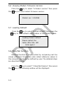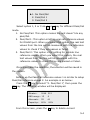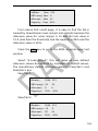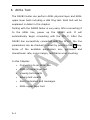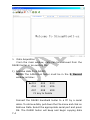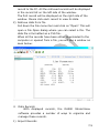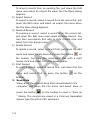
1
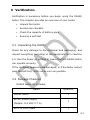
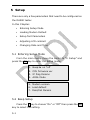
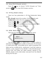
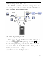
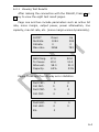
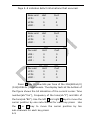
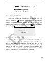
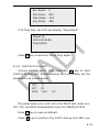
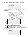
Contents
1
2
3
4
5
Introduction..........................................................1-1
1.1
Unpacking the DA280 .......................................1-1
1.2
Package Checklist ............................................1-2
External Appearance of DA280 ..............................2-1
Verification ...........................................................3-1
3.1
Unpacking the DA280 .......................................3-1
3.2
Package Checklist ............................................3-1
3.3
Power Supply and Battery Pack..........................3-2
3.4
Running a Power On Self Test ............................3-3
User Interface .......................................................4-1
4.1
User Keys .......................................................4-1
4.2
Front Panel Indicators.......................................4-2
4.3
Interface and Menu Management .......................4-3
Setup ....................................................................5-1
5.1
Entering Setup Mode ........................................5-1
5.2
Beep Setup .....................................................5-1
5.3
View CPU firmware version................................5-2
5.4
IP Ping Params Setup .......................................5-2
5.5
ADSL Mode Setup ............................................5-2
5.6
Viewing Modem firmware Version .......................5-3
5.7
Loading Default ...............................................5-3
5.8
Pass/Fail function .............................................5-3
V1.0
6
ADSL Test .............................................................6-1
6.1
Connecting to an ADSL Line ..............................6-2
6.2
ADSL physical layer Test ...................................6-2
6.2.1
6.2.2
6.2.3
6.3
7
8
Viewing Test Results ...................................6-4
Saving Test Results.....................................6-6
Alarm Indicators and Messages ....................6-6
ADSL upper layer test.......................................6-7
6.3.1
PPPoE/PPPoA &IP Ping test...........................6-7
6.3.2
RFC1483 Bridge/Route Static IP Ping test ....6-10
6.3.3
DHCP & IP Ping test ..................................6-12
6.3.4
ADSL Modem Simulation ...........................6-14
6.3.5
LAN Test .................................................6-15
6.3.6
DMM Test ................................................6-16
Record Management .............................................7-1
7.1
Entering Record Mode.......................................7-1
7.2
Viewing Records ..............................................7-1
7.3
Deleting Records..............................................7-2
7.4
Clear all records ..............................................7-2
7.5
Saving Records to a PC.....................................7-2
7.5.1
Install StreamViewII-ez Software .................7-3
7.5.2
Start StreamViewII-ez Software ...................7-3
Appendix A: Quick start.........................................8-1
V1.0
1 Introduction
The DA280 is a handheld tester, which provides a quick
and
accurate
evaluation
/ADSL2/ADSL2+.
of
parameters
on
the
ADSL
These parameters include max bit rate,
noise margin, power attenuation, and much more. With a four
hour rechargeable lithium battery and many applied functions,
it is the ideal tester for initial installations, maintenance, and
troubleshooting.
1.1 Main Functions
Support ADSL1/ADSL2/ADSL2+.
Measures: downstream/upstream bit rate, maximum bit
rate, relative capacity, noise margin, output power,
attenuation and more.
IP Ping test with PPPoE/PPPoA protocols.
RFC1483 Bridge/Route Static IP Ping test.
IP Ping test with DHCP protocols.
Displaying bits per tone in both graphical and table format.
Counts: FEC, HEC and CRC error frames for near end
and far end.
Detects and Indicates: Loss of signal, Loss of frame,
Loss of power, Loss of cell delineation, Loss of margin,
and more.
Displays: Real-time line status.
Alarms: audible and LED indicators.
1-1
Fully automatic range DMM test function, include Loop
resistance test, Capacitance test, Insulation resistance
test and AC/DC voltage test.
Critical line parameters value limitation setup.
1.2 Key Features
•
Power-up ADSL Acceptance Test.
•
Auto Synchronize with DSLAM ATU-C.
•
Verify level of service: bit rates and noise margin.
•
Pass/Fail indicatior.
•
Full modem emulation for any ADSL application
•
Build-in 10/100M ethernet port for a fast PC connection.
•
Easy operation and storage of system settings.
•
Save many test results, which can be downloaded to a PC
for management and printing.
•
Supports firmware upgrade to keep pace with changing
specifications.
•
Large capacity lithium battery, automatic charging and
battery fill gauge display.
1-2
2 External Appearance of DA280
2-1
2-2
3 Verification
Verification is necessary before you begin using the DA280
tester. This chapter provides an overview of your tester.
•
Unpack the tester
•
Accessories checklist
•
Check the capacity of battery pack
•
Running a self-test
3.1 Unpacking the DA280
Check for any damage to the container and packaging, and
inspect everything according to the equipment list in Section
2.2. Run the Power on selftest to insure that the DA280 tester
can operate properly.
If the container appears to be damaged, or if the tester cannot
pass the self-test, notify us as soon as possible.
3.2 Package Checklist
DA280 tester kit includes:
Name
DA280 tester
Quantity
1
AC-DC power supply
1
(Output: 8.4 VDC 0.7 A)
RJ11 to RJ11 cable
1
3-1
RJ11 to Alligator cable
1
PS/2 serial cable
1
Cross-over cable Cat5
1
User manual
1
CD (with StreamViewII-ez)
1
Carrying case
1
3.3 Power Supply and Battery Pack
A 8.4V AC-DC power supply and internal rechargeable lithium
battery pack are included with the DA280 tester. The internal
rechargeable lithium battery pack will last for four hours after
it is fully charged.
The battery pack will automatically be charged when the
DA280 is powered by the AC-DC power supply. When the
battery has been completely charged, the color of the Charge
status indicator LED in power supply will change from red to
green. The battery fuel gauge on the LCD display will show the
remaining capacity of the battery.
For internal rechargeable lithium battery pack, please
notice:
Do not dispose of in fire or put into water.
Do not disassemble or short circuit.
Do not use in high temperature or near a heat
source.
3-2
3.4 Running a Power On Self Test
DA280 will run a self-test every time the power is turned
on. This is done to insure that it is ready to operate properly.
Step
Operation
1
Power on
Explanation
Press the
button once. The LCD
display will start to run initialization and
then display the model of tester if
self-test passed. The tester will beep
once when it is ready to use.
2
Check battery
status
If the “Power” LED is dim or off, the
battery must be recharged or the AC
power supply must be used.
3-3
4 User Interface
The DA280 tester is very easy to use. The LCD display will
show all of the related information for your operation. To take
full advantage of all the features and benefits of the DA280, be
sure to read this chapter thoroughly.
In this Chapter:
•
User Keys
•
Front Panel Indicators
•
Interface and Menu Management
4.1 User Keys
The DA280 utilizes 20 keys. The 10 Digit keys are used to
input: digits, letters and symbols.
The other ten keys have fixed definitions and are described
below:
Name
Function
This is the power switch. Press once and hold
on for 2 seconds, power is on; press again and
hold on for 2 seconds, power is off.
Press once, LCD backlight is on, press again,
backlight is off (default status is off after
reset).
OK
4-1
Confirms an operation. Acts like the “Enter”
button on a PC.
∧
Generally, this key used for moving the
cursor up. In upper layer parameters setup,
this key is used for special functions, such
as to delete a parameter.
∨
This key is used for moving the cursor down.
In upper layer parameters setup, this key is
used for special functions, such as to select
next parameter.
<
This key is used for moving the cursor left.
>
This key is used for moving the cursor right.
ESC
Return to the last menu.
F1
This key is used for a special function in
specific interfaces. Such as: delete a record
in the Record interface or to save the test
results in the Physical Layer test interface.
F2
This key used for a special function in
specific interfaces. Such as: clear all records
in the Record interface or run an upper layer
test in the Upper Layer test interface.
4.2 Front Panel Indicators
There are four indicators on the front panel of the DA280
tester: one Power indicator and a group of Working indicators.
4-2
Type
Battery
Indicator
Label
Meaning
Power
The brighter the LED is the higher
the remaining capacity of the
lithium battery pack.
¤:
LAN
The tester has successfully
connected to the Ethernet.
Working
Indicators
¤:
DSL
The tester has successfully
connected to the DSLAM.
Alarm
¤:
A ADSL network problem has
been detected.
4.3 Interface and Menu Management
After a power up, the DA280 will display the main menu as
shown below:
►1.
2.
3.
4.
ADSL Test
Record
Setup
DMM Test
The DA280 is now ready to run the arrow pointed menu
item. Please press the OK key to start the selected function or
use the cursor keys to choose another function.
The main Menu displays four menu items whose functions
are defined as follows:
4-3
Menu
Function
ADSL
Test
Enter ADSL test status including ADSL Physical
test and ADSL upper layer test.
Record
View or delete a record or all records.
Setup
Setup each test condition,
version, date and time.
DMM
Test
Execute DMM test, includes loop resistance test,
insulation resistance test, AC/DC voltage test
and capacitance test.
View
firmware
To exit any of the menu functions, press the ESC key.
4-4
5 Setup
There are only a few parameters that need to be configured on
the DA280 tester.
In this Chapter:
•
Entering Setup Mode
•
Loading Modem Default
•
Setup Test Parameters
•
Adjusting LCD contrast
•
Changing Date and Time
5.1 Entering Setup Mode
From the main menu, move the cursor to “3. Setup” and
press the OK key to enter the Setup mode.
1.
2.
3.
4.
Beep:► on *off
CPU firmware ver
IP Ping Params
ADSL Mode
5. Modem version
6. Load default
7. Pass/Fail Params
5.2 Beep Setup
Press the ∨ key to choose “On” or “Off” then press the OK
key to select the setting.
5-1
5.3 View CPU firmware version
Press the ∨ key to choose “2.CPU firmware ver” then
press the OK key to view CPU firmware version.
5.4 IP Ping Params Setup
There are two parameters in IP Ping Parameters Setup
mode:
No. of sent means the number of ping packets sent.
Packet size means the size of each ping packet.
Press the < or > key to change the value.
Press the ∨ key to switch between the two parameters.
Press the F1 key to save the setup.
5.5 ADSL Mode Setup
There are two Modes in ADSL Mode Setup mode:
ADSL1
►ADSL1/2/2+
You can select ADSL1 or ADSL1/2/2+. If ADSL1 option is
selected, the tester will be in ADSL1 multimode (T1.413 issue
2, G.dmt and G.lite). If the ADSL1/2/2+ option is selected, the
tester will be in ADSL1/2/2+ multimode. It will first make an
ADSL2+ mode request to the DSLAM. If the DSLAM doesn't
support this, the tester will make another request to the
DSLAM, based on the information returned from the DSLAM
during the first poll.
5-2
5.6 Viewing Modem firmware Version
Press the ∨ key to select “5.Modem version” then press
the OK key to view modem firmware version.
Modem ver: 1104586
5.7 Loading Default
Press the ∨ key to select “6.Load default” then press the
OK key to Load default configuration of the inside modem.
Loading Modem default
Please restart the
tester after DSL LED
blink again!
5.8 Pass/Fail function
Pass/Fail function is implemented by comparing real line
values with their thresholds (also called reference values in
this manual), which can be defined by user. The detailed steps
are described below.
Press the ∨ key to select “7.Pass/Fail Params”, then press
the OK key. The following window will be displayed:
5-3
►1. No Pass/Fail
2. Pass/Fail 1
3. Pass/Fail 2
Select option 1, 2 or 3 via ∧ or ∨ key for different Pass/Fail
mode.
1. No Pass/Fail: This option means the unit doesn’t do any
pass/fail.
2. Pass/Fail 1: This option is letting user set reference values
for DSLAM port. When you select this option, the real test
values from the line will be measured with the reference
values to check if they are passes or failed.
3. Pass/Fail 2: This option is for setting for outside line
reference values. When you select this option, the real
test values from the line will be measured with the
reference values to check if they are passed or failed.
Once you made the selection, the selection will be saved in
the system.
Setting up the Pass/Fail reference values 1 is similar to setup
Pass/Fail reference values 2. An example is as below:
Press the ∨ key to select “2. Pass/Fail 1”, then press the
OK key. The following window will be displayed.
Bitrate>:
2048
512
SNR marg>: 15
6
Attenuat<:
55
40
Capacity<:
80%
80%
From this screen, press the ∧ key to delete current
5-4
parameter, using the ∨
key to move to next parameter. The
number key 0-9 will be used to input the number, while F1 key is
used to save the setting.
The Pass/Fail indication will be shown like below if all
parameters are passed:
Pass/Fail 1 result:
Pass!
Otherwise it will be shown as:
Pass/Fail 1 result:
Fail!
The pass/fail results will be displayed on the result window as
the real test values are on the left side and reference values are
on the right side. If a test value is passed, a “Pass” will be
displayed for that parameter.
There are 2 pages of the test results. One is for
downstream parameters and another is for upstream
parameters.
5-5
DownRate: Pass
2048
SNR marg: 13.5
15
Attenuat:
Pass
55
Capacity:
85%
80%
UpRate:
Pass 512
SNR marg: Pass
6
Attenuat:
Pass
40
Capacity:
Pass 80%
From above first result page, it is easy to find the fail is
caused by downstream noise margin and capacity because the
reference value for noise margin is 15 and the test value is
13.5 (less than the threshold) and the capacity is 85% and the
reference value is 80%.
Press the ESC key to go to the ADSL physical layer test
window.
Select “6.Load default”, this will make all user defined
reference values be replaced by manufactory default values.
The manufactory default reference values for Pass/Fail 1 and
Pass/Fail 2 are:
Pass/Fail 1:
Bitrate>:
2048
512
SNR marg>: 30
20
Attenuat<:
5
5
Capacity<:
30%
60%
2048
512
Pass/Fail 2:
Bitrate>:
SNR marg>: 15
6
Attenuat<:
55
40
Capacity<:
80%
80%
5-6
6 ADSL Test
The DA280 tester can perform ADSL physical layer and ADSL
upper layer tests including a LAN Ping test. Each test will be
explained in detail in this chapter.
Testing with the DA280 tester is very easy. After connecting it
to the ADSL line, power up the DA280 unit. It will
automatically begin connecting with the ATU-C. After the
DA280 has successfully connected with the ATU-C, the line
parameters can be checked in detail by pressing the OK key.
Some of the available parameters are: upstream and
downstream rate, noise margin, and frame error counting.
In this Chapter:
•
Connecting to an ADSL line
•
ADSL physical layer test
•
Viewing test results
•
Saving test results
•
Alarm indicators and messages
•
ADSL upper layer test
6-1
6.1 Connecting to an ADSL Line
The DA280 operates in terminal testing mode and
connects anywhere between the DSLAM and the ATU-R device.
This is illustrated in the following figure:
6.2 ADSL physical layer Test
After Power On, the DA280 immediately attempts to
connect with the Central Office (ATU-C). Press the OK key to
start the ADSL physical layer test. The LCD status displays the
connection status of the DA280 and the ATU-C, such as
“Waiting for connection…” or “Open
success!!” as shown in the display below:
6-2
Waiting for
Connection...
The “DSL” LED indicates the status of the ADSL line. If the
LED blinks slowly, this indicates that the unit is “waiting for
initialization.”
If
the
LED
blinks
rapidly,
this
signifies
“initializing.” If the LED stays on, this signifies “Showtime.”
When the connection is successful, the tester will beep
several times, the status will display “Open success!!,” and the
LCD display will show the current link mode and the line
parameters.
Open success!!
F1 key to save
F2 key to View
Bits Per Tone
If the DA280 fails to connect to the ATU-C, the “Alarm”
indicator on the front panel will illuminate and the Status will
display “connection fail!!”
Connection fail!!
6-3
6.2.1 Viewing Test Results
After making the connection with the DSLAM, Press ∧ or
∨ key to view the eight test result pages.
Page one and two include parameters such as active bit
rate, noise margin, output power, power attenuation, line
capacity, max bit rate, etc. (noise margin varies dynamically).
G.DMT
Fastrate:
Intlrate:
Max rate:
SNR Marg:
Tx Power:
Attenuat:
Capacity:
Down
1054
0
3856
17.0
22.0
58.0
62%
Up
384
0
783
22.0
12.0
21.0
33%
Pages Three and four display error statistics.
Fast FEC:
Intl FEC:
Fast CRC:
Intl CRC:
0
0
0
0
0
0
0
0
Fast HEC:
Intl HEC:
ES:
0
0
0
0
0
6-4
Page 5–8 indicates defect informations that occurred.
Near-end
LCD :
LCDi:
LOM :
Hist
0
0
0
Curt
0
0
0
Near-end
LCD :
LCDi:
LOM :
Hist
0
0
0
Curt
0
0
0
Far-end
LOS :
LOF :
LOP :
Hist
0
0
0
Curt
0
0
0
Far-end
LCD :
LCDi:
LOM :
Hist
0
0
0
Curt
0
0
0
Press F2 key to view bits per tone of the 256(ADSL1/2)
/512(ADSL2+) subchannels. The display texts at the bottom of
the figure shows the bit allocation of the current cursor. Tone
number(ab.”Ton”), Frequency of the tone(ab.”F”) and Bits of
the tone(ab.”Bit”). Use the left < and right > keys to move the
cursor position by one sub-channel for each key press. Use
the ∧ or ∨ key to move the cursor position by ten
sub-channels for each key press.
6-5
Ton: 64
F: 276
Bit:06
6.2.2 Saving Test Results
Once the DA280 has successfully connected with the
ATU-C, press the F1 function key to save the current test
results. A message displays “Save to No. xxx, Yes/No?”. If you
want to save the testing results, press the OK key; otherwise
press the ESC key to cancel the save operation.
Save to No.01
Yes/No?
6.2.3 Alarm Indicators and Messages
If the DA280 becomes disconnected from the ATU-C due to
external reasons, such as the ADSL line is cut, loss of power,
etc., it will generate an audible warning and turn on the
“ALARM” indicator on the front panel, and display ”Loss of
signal!” in the LCD display. Detailed alarm messages are
available on pages five to eight, the test results for both
current and historical occurrences are displayed.
6-6
6.3 ADSL upper layer test
Press the OK key to enter the selection of the upper layer
test mode. The menus will be displayed as shown below:
1.
2.
3.
4.
PPP Mode
Static Mode
DHCP Mode
Modem Mode
You can perform a PPPoE/PPPoA & IP Ping test, RFC1483
Bridge/Route static IP Ping test, DHCP & IP Ping test or
configure the DA280 as a ADSL Modem.
6.3.1 PPPoE/PPPoA &IP Ping test
Select 1. PPP Mode, then press the OK key to start the
PPPoE/PPPoA & IP Ping test. Since the operations of the two test
modes are very similar, only PPPOE test will be explained in detail
below.
Before running the test, please set the parameters shown
below.
VPI :
0
VCI :
35
MUX : *LLC
AUTH: *PAP
VC
CHAP
Use the ∨ key to move to the second page.
UsrN:blz0022089
Pswd:asd97DaD
6-7
The parameters you must set are:
VPI and VCI
MUX encapsulation type: LLC-SNAP/VC-MUX
AUTH (authentication): PAP/CHAP
UsrN: PPP account name
Pswd: PPP password
∨ key to select the parameter you want to set.
∧ key to delete the selected parameter’s value.
< or > key to select the left or right number/character and
confirm the current input.
The “0-9” keys are used to choose the numbers and
characters which you want to input.
The relationship of the numbers and the characters are
shown below:
num
-ber
char
0
0@. *#_
1
2
3
4
1abcABC
2defDEF
3ghiGHI
4jklJKL
num
-ber
5
6
7
8
9
char
5mnoMNO
6pqrPQR
7stuSTU
8vwxVWX
9yzYZ
Press F1 key to save as default.
Press F2 key to perform the PPPoE/PPPoA dial-up test after
you have finished the setup. The LCD displays is shown below:
PPPoE dialing…
6-8
If the PPPoE/PPPoA dial-up is successful,the LCD displays
is shown below:
PPPoE established!
Assigned IP:
218.23.102.7
If you need, the ESC key will take you back to the Physical
Layer screen and release the assigned IP address.
Press F2 key to enter the IP Ping test mode:
Assigned IP:
218.23.102.7
Target IP:
202.108.036.096
Now, you can change the target IP address.
Press F1 key to save as default target IP address.
Press F2 key to perform IP Ping test. After you finish the
setup, the LCD displays is shown below:
Target IP:
202.108.36.96
Pinging…
If IP Ping is successful the LCD displays is shown below:
6-9
Target IP:
202.108.36.96
Ping OK!
Rev Packs: 3
Min Delay: 290
Max Delay: 300
Avg Delay: 295
If IP Ping fails, the LCD will display ”Ping failed!”.
Press F2 key to perform the IP Ping again.
6.3.2 RFC1483 Bridge/Route Static IP Ping test
Select 2. Static Mode, then press the OK key to start the
RFC1483 Bridge/Route Static IP Ping test. Since the operations
of the two test modes are very similar, only RFC1483 Bridge
test will be explained in detail below.
Before running the test, please set the parameters shown
below.
VPI : 0
VCI : 35
MUX : *LLC
VC
Gateway:
218.21.65.193
Subnet mask:
255.255.255.192
6-10
Wan IP:
218.21.65.230
Target IP:
202.108.036.096
The parameters you must set are VPI, VCI, and MUX
encapsulation type LLC-SNAP/VC-MUX ) , Gateway, Subnet
mask, Wan IP, and Target IP in Static IP Ping test mode.
∨ key to select the parameter you want to set.
For VPI and VCI, ∧ key to delete their value.
For Gateway, Subnet mask, Wan IP and Target IP, > or >
key to select the left or right number.
Press F1 key to save as default.
Press F2 key to perform the IP Ping test.
The LCD displays is shown below:
Target IP:
202.108.36.96
Pinging…
If IP Ping successful, the LCD displays is shown below:
Target IP:
202.108.36.96
Ping ok!
6-11
Rev Packs: 3
Min Delay: 290
Max Delay: 300
Avg Delay: 295
If IP Ping fails, the LCD will display ”Ping failed!”
Target IP:
202.108.36.96
Ping failed!
Press F2 key to perform the IP Ping again.
6.3.3 DHCP & IP Ping test
Choose 3.DHCP Mode, then press the OK key to start
DHCP & IP Ping test. Before running the test, please set the
parameters as shown below.
VPI :
0
VCI : 35
MUX: *LLC
VC
The parameters you must set in the DHCP test mode are:
VPI, VCI, and MUX encapsulation type LLC-SNAP/VC-MUX.
Press F1 key to save as default.
Press F2 key to perform the DHCP dial-up test after you
6-12
have finished the setup. The LCD displays is shown below:
DHCP dialing…
If the DHCP dial-up is successful,the LCD displays is
shown below:
DHCP ok!
Assigned IP:
218.23.102.7
Gateway:218.23.102.1
Press F2 key to enter the IP Ping test mode:
Assigned IP:
218.23.102.7
Target IP:
218.108.36.96
Now, you can change the target IP address.
Press F1 key to save as default target IP address.
Press F2 key to perform IP Ping test after you finish the
setup, the LCD displays is shown below:
Target IP:
218.108.36.96
Pinging…
6-13
If IP Ping is successful the LCD displays is shown below:
Target IP:
218.108.36.96
Ping ok!
Rev Packs: 3
Min Delay: 290
Max Delay: 300
Avg Delay: 295
If IP Ping fails, the LCD will display ”Ping failed!”.
Press F2 key to perform the IP Ping again.
6.3.4 ADSL Modem Simulation
Choose 4. Modem Mode, then press the OK key to enter
ADSL Modem Simulation test mode.
Before running the test, please set the parameters as
shown below.
VPI :
0
VCI : 35
MUX: *LLC
VC
The parameters you must set in the ADSL Modem
Simulation test mode are: VPI, VCI, and MUX encapsulation
type LLC-SNAP/VC-MUX.
Press F1 key to save as default.
6-14
Press F2 key to configure the DA280 as a ADSL Modem.
The LCD displays is shown below:
ADSL Modem
Simulation Mode
6.3.5 LAN Test
The LAN test allows the tester to be connected to the LAN
as a terminal and Ping the IP address of other LAN ports. This
can help discover any connection problems on the LAN.
HUB
10/100BASE-T
Before Testing: You need to set the IP address (source IP
address) of your tester in the same format as your local LAN.
For instance, if your LAN port IP addresses are in the range
of 192.168.0.XXX, then you can set your tester as
192.168.0.200. Make sure that the new address does not have
any conflicts with other LAN port addresses.
Press F1 key on the main menu to start Ethernet IP Ping
Test. Before running the test, please set the parameters as
shown below.
6-15
Local IP: <LAN Test>
192.168.000.200
Target IP:
192.168.000.088
key to select the parameter you want to set.
> or > key to select the left or right number.
Press F1 key to save as default target IP address.
Press F2 key to perform IP Ping test.
6.3.6 DMM Test
The DA280 has fully automatic range DMM.
The DMM test includes loop resistance test, insulation
resistance test, AC/DC voltage test and capacitance test.
Test schematics:
Measure the loop resistance and estimate the line length:
Line
Add a Short on the far end.
Measure the capacitance and estimate the line length:
Line
6-16
Test for the insulation resistance and AC/DC voltage:
Line
From the main menu, move the cursor to “4.DMM Test”
and press the OK key to enter the DMM test mode.
1.
2.
3.
4.
Resistance
Capcitance
DC Voltage
AC Voltage
5. Insulation
▼
▲
Use the
and
keys to choose the test mode you want
and press the OK key to perform the test.
Press the ESC key to exit DMM test mode.
Attention:
If there is a voltage on the ADSL line, the top line of the
LCD will display “Voltage!” and the loop resistance test,
capacitance test and insulation resistance test, will not be
able to display any results.
If “Overflow!” is displayed on the top line of the LCD,
than the test results have exceeded the maximum test
range limitation.
6-17
7 Record Management
The DA280 tester provides nonvolatile storage space.The
records can be viewed and deleted.
In this Chapter:
•
Entering Record Mode
•
Viewing Records
•
Deleting Records
•
Saving Records to a PC
7.1 Entering Record Mode
From main menu, move the cursor to the “2.Record” menu
item and then press the OK key.
►#01
#02
#03
#04
#05
#06
#07
#08
#09
F1 key to Delete
Use the
and
keys to choose the record you want to view
and press the OK key to view.
7.2 Viewing Records
Every record includes eight pages, each of which
corresponds to a page of the in-field test results.
7-1
7.3 Deleting Records
To delete the highlighted record, press the F1 key. The
message “Delete No. xx, Yes/No” will display.
If you want to delete the test results, press the OK key;
otherwise press the ESC key to cancel the delete operation.
Delete No.05,
Yes/No?
7.4 Clear all records
To delete all records, press the F2 key. The message
“Clear all records, Yes/No?” will display.
If you want to delete the test results, press the OK key;
otherwise press the ESC key to cancel the delete operation.
Clear all records,
Yes/No?
7.5 Saving Records to a PC
The test results of the DA280 tester can be easily saved to
a PC via the RS232C serial port. Before doing so, you will need
to install the StreamViewII-ez software program on your PC.
To install and operate the software for Windows
95/98/2000/XP and NT, follow the steps below:
7-2
7.5.1 Install StreamViewII-ez Software
Insert the supplied CD and from “My computer”,
double-click on “Setup.exe”. When setup is finished, connect
the DA280 tester to the computer as shown in the following
figure:
PS/2
PS/2 Serial Communication Cable
PC
Serial Port
7.5.2 Start StreamViewII-ez Software
Click on the Windows “Start” menu and choose “Programs”
->”StreamViewII-ez”->”StreamViewII-ez”
to
start
the
software.
The main window of the StreamViewII-ez software
displays as shown below:
7-3
1. Data Acquisition
From the main window, data can be retrieved from the
DA280 tester or an existing file.
1) Retrieve data from DA280
NOTE: The ADSL2+ez tester must be in the 2. Record
window as blow:
►#01
#02
#03
#04
#05
#06
#07
#08
#09
F1 key to Delete
Connect the DA280 handheld tester to a PC by a serial
cable. To retrieve data, pull down the File menu and click on
Retrieve Data. Select the appropriate serial port and press
OK. The DA280 tester will beep and begin copying data
7-4
record to the PC. All the retrieved records will be displayed
in the record list on the left side of the window.
The first record will be displayed on the right side of the
window. Mouse click each record to view its data.
2) Retrieve data from file
Pull down the File menu item and click on “Open”. This will
open a File Open dialog where you can select a file. The
data file is formatted as a CVS file.
When all the records have been either downloaded to the
computer or opened from a file, you will see a window as
seen below:
2. Data Records
With displayed records, the DA280 StreamView
software provides a number of ways to organize and
manage these records.
1) Import Records
7-5
To import records from an existing file, pull down the Edit
menu and select an import file when the File Open dialog
appears.
2) Export Record
To export a record, select a record from the record list, pull
down the Edit menu and select an export file name when
the File Save dialog appears.
3) Rename Record
To rename a record, select a record from the record list,
pull down the Edit menu and select Rename Record. You
may also accomplish this with a right mouse click and
select from the popup menu.
4) Delete Record
To delete a record, select a record first, pull down the Edit
menu and select Delete Record or press the button
on
the toolbar. You may also accomplish this with a right
mouse click and select from the popup menu.
5) Print Record
To print a record, select a record first, pull down the File
menu and select Print or press the button
on the
toolbar.
3. Save Data
When all of the records have been downloaded to the
computer, pull down the File menu and select Save or
press the button
on the toolbar to open a “Save as
“ dialog. The records are saved in a Common Separated
Values type file with a CSV extension.
7-6
8
Appendix A: Quick start
PPPoE dial up and IP Ping test (Non-Static IP):
1-Plug the ADSL line connector into the DA280 RJ11 port.
2-Choose 1. ADSL Test and then press OK key on the main
menu.
3-Once the DA280 has successfully connected with the DSLAM,
press OK key then choose 1. PPP Mode.
4-Press OK key then choose 1. PPPoE.
5-Press OK key then enter the VPI, VCI, Account and
Password.
6-Press F2 key, it will give the PPPoE results. If successful,
press F2 key then enter the target IP.
7-Press F2 key, it will give the IP Ping results.
PPPoA dial up and IP Ping test (Non-Static IP):
1-Plug the ADSL line connector into the DA280 RJ11 port.
2-Choose 1. ADSL Test and then press OK key on the main
menu.
3-Once the DA280 has successfully connected with the DSLAM,
press OK key then choose 1. PPP Mode.
4-Press OK key then choose 2. PPPoA.
5-Press OK key then enter the VPI, VCI, Account and
Password.
6-Press F2 key, it will give the PPPoA results. If successful,
8-1
press F2 key then enter the target IP.
7-Press F2 key, it will give the IP Ping results.
RFC1483 Bridge Static IP Ping test:
1-Plug the ADSL line connector into the DA280 RJ11 port.
2-Choose 1. ADSL Test and then press OK key on the main
menu.
3-Once the DA280 has successfully connected with the DSLAM,
press OK key then choose 2. Static Mode.
4-Press OK key then choose 1. RFC1483 Bridge.
5-Press OK key then enter the VPI, VCI, Wan IP, Gateway,
Subnet Mask and Target IP.
6-Press F2 key, it will give the IP Ping results.
RFC1483 Route Static IP Ping test:
1-Plug the ADSL line connector into the DA280 RJ11 port.
2-Choose 1. ADSL Test and then press OK key on the main
menu.
3-Once the DA280 has successfully connected with the DSLAM,
press OK key then choose 2. Static Mode.
4-Press OK key then choose 2. RFC1483 Route.
5-Press OK key then enter the VPI, VCI, Wan IP, Gateway,
Subnet Mask and Target IP.
6-Press F2 key, it will give the IP Ping results.
8-2
DHCP dial up and IP Ping test (Non-Static IP):
1-Plug the ADSL line connector into the DA280 RJ11 port.
2-Choose 1. ADSL Test and then press OK key on the main
menu.
3-Once the DA280 has successfully connected with the DSLAM,
press OK key then choose 3. DHCP MOde.
4-Press OK key then enter the VPI, VCI.
5-Press F2 key, it will give the DHCP results. If successful,
press F2 key then enter the target IP.
6-Press F2 key, it will give the IP Ping results.
ADSL Ethernet modem:
1-Connect the Ethernet cable between DA280 Ethernet port
and PC Ethernet port. Plug ADSL line connector in DA280 RJ11
port.
2-Choose 1. ADSL Test and then press OK key on the main
menu.
3-Once the DA280 has successfully connected
with the DSLAM, press OK key then choose 4. Modem Mode.
4-Press OK key then enter the VPI, VCI.
5-Press F2 key.
6-Internet Login and surfing on a PC.
8-3
DMM test:
1-Plug the ADSL line connector into the DA280 RJ11 port.
2-Choose 4. DMM Test and then press OK key on the main
menu.
3-Select the test mode you want and press the OK key to
perform the test.
8-4