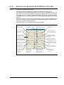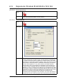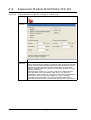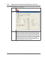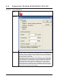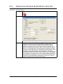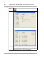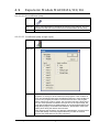
1
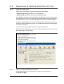
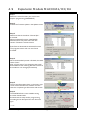
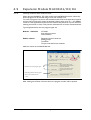
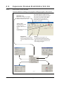
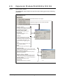
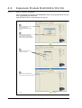
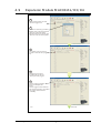
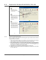
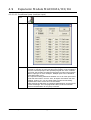
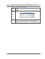
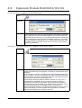
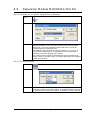
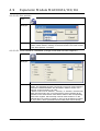
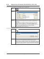
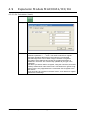
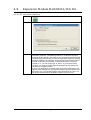
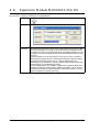
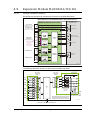
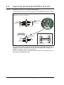
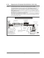
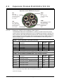
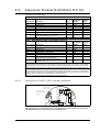
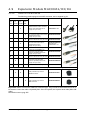
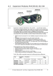
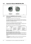
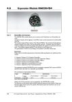
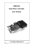
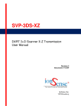
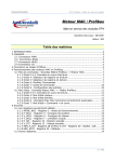
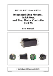
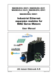
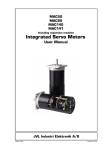
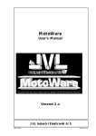
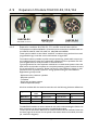
4.9
Expansion Module MAC00-R1/R3/R4
MAC00-R1
4.9.1
MAC00-R4
MAC00-R3
With DSUB connectors
With M12 connectors
With cable glands
Expansion modules MAC00-R1, R3 and R4 overall description
The expansion modules MAC00-R1, R3 and R4 can be mounted on standard MAC motors MAC50, MAC95, MAC140, MAC141, MAC400 and MAC800.
These option modules are also called “nanoPLC” modules as they perform like a small
programmable logic controller with a small number of digital I/Os.
The module makes it possible to perform simple positioning, speed and/or torque control via 8 digital inputs which all are galvanically isolated and can be operated with 24V
control signals from for example a PLC or external sensors.
Typical applications for these expansion modules are in stand-alone systems where the
MAC motor must be able to operate as a complete positioning system without the need
for an external PLC or computer. Please note that it is also possible to change or read
parameters such as position, speed etc. during operation using the serial interface.
Applications typically include:
- Replacement for pneumatic cylinders.
- Dispenser systems
- Turntables
- Simple pick and place systems
- Machine adjustment/setup.
All of the modules offer the same functions but with the following hardware differences:
Type
Protection
class
Connectors
I/O and interface
Power supply
LEDs at I/O
MAC00-R1
IP42
DSUB 9 pole
3 pole Phoenix
Yes
MAC00-R3
IP67/IP65*
Cable glands
Cable glands
No
M12
M12
No
IP67/IP65*
MAC00-R4
Note*: IP65 on MAC400-800
The MAC00-R3 module can also be delivered with cable in selected lengths. Cables with
M12 connectors can also be supplied for the MAC00-R4 module.
The first part of this section deals with the common features of both modules. Please see
the latter pages of the section for see specific information about each module (for example, connection diagrams).
212
JVL Industri Elektronik A/S - User Manual - Integrated Servo Motors MAC050 - 800
4.9
Expansion Module MAC00-R1/R3/R4
4.9.2
Important before use
Please note that two different types of firmware setup are available.
- Graphic programming setup (Firmware MAC00-RxP).
- Fixed formats (MAC00-Rx). See User Manual LB0047-18GB
Until Q3 2004, the only firmware available was the “fixed format type”. Since this date
the fixed format firmware has not been updated and the Graphic Programming Setup is
the preferred type, i.e. all new modules by default contain this new type of firmware.
The graphic programming firmware offers 100% flexibility since almost any function in
the motor can be controlled using simple, user-friendly commands that are built together
as a sequential program.
The user interface of both types of firmware setup is shown below.
Note: If MacTalk is used off line (no motor connected), all tabs can be seen by selecting
Show hidden pages in the View menu.
Graphic programming.
The module setup with graphic programming
firmware (MAC00-RxP).
Simple user-friendly commands can be built
together forming a program with the desired
function for the application.
The function of each input and output can be
user defined
TT1078GB
4.9.3
How to set up the desired firmware
Use the following step-by-step instruction to set up the desired firmware.
(continued next page).
JVL Industri Elektronik A/S - User Manual - Integrated Servo Motors MAC050 - 800
213
4.9
Expansion Module MAC00-R1/R3/R4
Step 1
Determine which firmware you want to use:
Graphic programming (MAC00-RxP).
Step 2
Choose the Firmware update in the Updates menu.
Step 3
Make sure that the checkbox “Show all files”
is checked.
Select the desired firmware, MAC00-RxP.
Note that there may exist more than one
version. Choose the newest version.
Press Start to download the selected firmware.
The progress counter will now rise from 0
to 100%.
Step 4
When the download process is finished, the status
shows “Done”.
Also “Current version” has changed to the actual
downloaded version meaning that the firmware in
the module is now changed permanently.
Step 5
The on-line information shown in the lower right
corner of the MacTalk main window will now
show the complete type of firmware and version.
Step 6
The MAC00-RxP tab is now available among
the other standard tabs.
Proceed with the setup and/or programming
according to the description for each firmware
type.
TT1079GB
214
JVL Industri Elektronik A/S - User Manual - Integrated Servo Motors MAC050 - 800
4.9
Expansion Module MAC00-R1/R3/R4
4.9.4
Getting started with MAC00-RxP
When using the MAC00-R1, R3 or R4 module with MAC00-RxP firmware, almost any
kind of program can be created using a set of user-friendly icons.
To create a program, first of all it must be determined whether the application requires
that the motor always stays within the allowed position range which is +/- 67.108.863
counts or if the application requires that the motor mostly moves in only one direction,
meaning that sooner or later it will pass the maximum limit of counts mentioned above.
Typical applications for the two program types are:
Relative + Absolute
XY tables
Pick and place robots
Valve actuators
Endless relative
Dispensers for film, labels etc.
Dosing pumps
Turntables
Torque-controlled screw machines
Make the choice on the MAC00-RxP tab.
Choose one of these program types
Or
Optionally upload the actual program
stored in the module last time.
TT0980GB
After making one of these 3 choices above, the program window will be opened.
JVL Industri Elektronik A/S - User Manual - Integrated Servo Motors MAC050 - 800
215
4.9
Expansion Module MAC00-R1/R3/R4
4.9.5
MAC00-RxP Main window
The main window for creating a new program or editing a program is shown below:
MAC00-RxP Status texts
The message Program not transferred means
that there is a difference between the program
seen on the screen and the actual program in
the module. This can happen if the program
have been edited but not transferred.
Status: Running (or Stopped) refers to the
program in the module.
MAC00-RxP menu
Main menu for creating a new program,
Verifying program size and other basic
details for the MAC00-RxP module.
Transfer & Start
Will transfer the complete
program and start it.
Use Stop or Pause to stop it.
Stop
Use this button if the program
must be stopped.
Program lines
Each button represents a program
line. By pushing the button a command can be entered at the program
line.
Pause
Use this button if the program must
be paused. Paused means that the actual
program line executed is temporarily paused.
When paused, the single step feature can be
used to debug the program.
TT0981GB
216
JVL Industri Elektronik A/S - User Manual - Integrated Servo Motors MAC050 - 800
4.9
Expansion Module MAC00-R1/R3/R4
4.9.6
MAC00-RxP menu
The MAC00-RxP menu found at the top of the main window gives access to following
possibilities:
MAC00-RxP menu:
Described elsewhere in this chapter
Upload the program from the module to MacTalk
Program + Source
Shows the memory usage if the program
(compiled)+source program and remarks
is downloaded into the module.
Program + Source - REM
Same as above but without remarks.
Program only
Same as above but without source
program and remarks.
Checksum
Shows the checksum of the complete
program downloaded into the module.
The checksum is unique and can be used
to verify whether the program in the
module matches the original program or
not.
Lines
The number of program lines used in the
source program (MacTalk)
Mode
Specify the program type actually used.
Enable input filter
Enables an oversampling filter at the inputs IN1 to IN8.
This feature can be used to remove noise from the inputs.
Skip initialization (advanced)
Bypasses internal initialization routines after powerup.
(Only for very special use).
Program + Source + Remarks
Default. Choosing this will transfer everything into the
module memory. This can be an advantage if remarks
and source program must be uploaded to MacTalk later.
Program + Source
Same as above but without remarks.
Program only
Only the compiled program is transfered.
TT0982GB
JVL Industri Elektronik A/S - User Manual - Integrated Servo Motors MAC050 - 800
217
4.9
Expansion Module MAC00-R1/R3/R4
4.9.7
How to build a program
When choosing New program in the MAC00-RxP menu or entering MacTalk for the first
time, programming can be started.
Press the button at line 1 and a tool box will pop up.
1
Press the first button to create
the first program line.
The “Select command” box will
pop up.
2
Choose the desired command.
In this example it is desired to
wait for an input to be activated
before further program execution.
3
Choose to wait until input 5
is high and press OK
4
The command is inserted at the
previous selected program line
TT0983GB
218
Continued
JVL Industri Elektronik A/S - User Manual - Integrated Servo Motors MAC050 - 800
4.9
Expansion Module MAC00-R1/R3/R4
5
Press the second button to create
the second program line
6
Choose the movement type needed.
Relative: Move x counts forward with
reference to the actual position.
Absolute: Move to the x position with
reference to the zero search position.
7
The relative move command just
entered is converted into a program
line.
8
Multiple program lines are
entered by the user forming
the last part of the program.
9
Now the program is finished.
Press the “Transfer & Start”
button.
Now the program will be transfered
and stored permanently in the module.
The program will be executed
immidiately
TT0984GB
Continued
JVL Industri Elektronik A/S - User Manual - Integrated Servo Motors MAC050 - 800
219
4.9
Expansion Module MAC00-R1/R3/R4
10
Now the program is running
continuously. The actual program
line which is executed is shown
by the small red arrow.
11
By choosing the “Pause” button, the
program is paused. After it is paused,
it is possible to single step through
each program line which can be a
useful feature to debug the program
since the action in each line can be
closely observed.
12
When the program is finished, it can
be saved on the harddisc or floppy
disc. Please be aware that when
saving the program it is the complete
program including the overall setup
of the motor such as servofilter, I/O
setup etc. Everything is stored in a file
with the extension .MAC. Later it can
be opened and restored in the motor.
TT0985GB
4.9.8
General programming hints
When a program is built and saved, the following hints may be useful to ensure that the
program behaves as expected.
1. When transferring the program to the module it is saved permanently in the memory
and the program will be executed each time the motor is switched on.
2. Before making a program, ensure that the basic parameters for controlling acceleration, torque, safety limits, etc. are set to proper values. When saving the program on
the hard disk or floppy disk, all of these basic parameters will be saved together with
the program as a complete motor setup package.
3. A program line can be edited by double-clicking the command text.
4. When the cursor is placed on top of the command icon, an edit menu can be called
up with a right-click.
220
JVL Industri Elektronik A/S - User Manual - Integrated Servo Motors MAC050 - 800
4.9
Expansion Module MAC00-R1/R3/R4
4.9.9
Command toolbox description
The toolbox used for programming comprises 16 different command types.
The idea is for the commands to give easy access to the most common functions in the
motor. Some functions may seem to be missing at first sight but the buttons “Set register
in the MAC motor” or “Wait for a register value before continuing” give direct access to
+50 registers down in the basic MAC motor, such as the gear ratio or the actual torque
register.
In total this provides a very powerful programming tool since >95% of a typical program
can be built using the simple command icons and the remaining part is obtained by accessing the basic motor registers directly.
A short description of all 16 command icons is given below.
Use: Initiates any
motor movement
relative or absolute.
Use: Inserts a remark/
Comment in the program
source code.
Use: Set the motor in the
desired mode such as
position- or velocity mode.
Use: Set a certain
state at one or multiple
digital outputs.
Use: Unconditional
jump from one program
line to another.
Use: Conditional jump
from one program line
to another. Input dependent
Use: Inserts a delay in
the program specified
in milliseconds.
Use: Wait for a certain
state at one or multiple
digital inputs.
Use: Write a value
to almost any register in
the basic MAC/MIS motor.
Use: Conditional jump
from one program line to
another. Register dependent
Use: Wait for a certain
state at one or more of
the digital inputs.
Use: Save the actual motor
position to an intermediate
register.
Use: Initiates a zero
search to a sensor or
a torque (no sensor).
Use: Preset the position
counter to a certain value.
Use: Change mode
and activate register
using a single
command.
Use: Performs a
calculation using
register values
and contants.
TT1103GB
Use: Compares two
registers to each other
before jumping or
moving in the program.
Use: Binary format
instead of graphic
commands.
JVL Industri Elektronik A/S - User Manual - Integrated Servo Motors MAC050 - 800
221
4.9
Expansion Module MAC00-R1/R3/R4
4.9.10
RxP Command Reference
4.9.10.1
Enter your own remarks
Icon:
Dialogue:
Function:
4.9.10.2
Inserts a remark/comment in the source code. The program line will not
do anything, but can make the source code easier to read. This can be
very important, if other programmers have to review or work on the code,
or if the program is only worked on infrequently.
Set operation mode
Icon:
Dialogue:
Function:
222
Sets the operating mode for the motor. When the program encounters a
program line with this command, the motors operating mode will be set to
the specified mode. This allow you to use different operating modes in
different parts of the program. For a detailed description of the individual
operating modes, refer to section 1.2.1
JVL Industri Elektronik A/S - User Manual - Integrated Servo Motors MAC050 - 800
4.9
Expansion Module MAC00-R1/R3/R4
4.9.10.3
Move operations
Icon:
Function:
4.9.10.4
The Move command is very flexible, with five different operating modes.
Each mode will be described in its own section
Move Relative
Icon:
Dialogue:
Function:
Performs a movement relative to the current position. The distance
moved is measured in encoder counts, and can either be entered directly, or taken from three memory registers in the RxP module. For further
information on using these memory registers, refer to the sections on the
“Save position” and “Set position” commands. Note that if you specify a
velocity, motor register no. 5 (V_SOLL) will be over written with this
velocity value. Also, if you specify an acceleration, motor register no. 6
(A_SOLL) will be overridden with the acceleration value you specified.
Register no. 49 (P1) is always over written by this command If the “Wait
for in position” option is checked, the program will wait until the motor has
finished the movement, before proceeding to the next program line. If this
option is not checked, the program will start the movement, then
immediately start executing the next command. The motor will finish the
movement on its own, unless it is given other instructions by the program.
JVL Industri Elektronik A/S - User Manual - Integrated Servo Motors MAC050 - 800
223
4.9
Expansion Module MAC00-R1/R3/R4
4.9.10.5
Move (Relative + velocity change at a distance)
Icon:
Dialogue:
Function:
224
Performs a relative movement, and changes velocity a specified distance
before reaching the new position. The distance are measured in encoder
counts, and can either be entered directly, or taken from three memory
registers in the RxP module. For further information on using these
memory registers, refer to the sections on the “Save position” and “Set
position” commands.
Note that motor register no. 5 (V_SOLL) will be over written with the
value specified in the “New velocity” field. Also, if you specify an
acceleration, motor register no. 6 (A_SOLL) will be over written with the
acceleration value you specified. Register no. 49 (P1) is always
overridden by this command. This command always wait until the
movement is finished, before proceeding to the next line in the program.
JVL Industri Elektronik A/S - User Manual - Integrated Servo Motors MAC050 - 800
4.9
Expansion Module MAC00-R1/R3/R4
4.9.10.6
Move (Relative + set outputs)
Icon:
Dialogue:
Function:
Performs a movement relative to the current position, and sets one or
more outputs on the RxP module when the operation is completed. The
distance moved is given in encoder counts, and can either be entered
directly, or can be taken from one of three memory register in the RxP
module. For further information on using these memory registers, refer to
the sections on the “Save position” and “Set position” commands. Note
that if you specify a velocity, motor register no. 5 (V_SOLL) will be over
written with this velocity value. Also, if you specify an acceleration, motor
register no. 6 (A_SOLL) will be over written with the acceleration value
you specified. Register no. 49 (P1) is always over written by this
command. This command always wait until the movement is finished,
before proceeding to the next line in the program.
JVL Industri Elektronik A/S - User Manual - Integrated Servo Motors MAC050 - 800
225
4.9
Expansion Module MAC00-R1/R3/R4
4.9.10.7
Move (Absolute)
Icon:
Dialogue:
Function:
226
Moves to an absolute, non-relative position. The position is given in
encoder counts, and can either be entered directly, or can be taken from
one three memory register in the RxP module. For further information on
using these memory registers, refer to the sections on the “Save position”
and “Set position” commands.
Note that if you specify a velocity, motor register no. 5 (V_SOLL) will be
overwritten with this velocity value. Also, if you specify an acceleration,
motor register no. 6 (A_SOLL) will be over written with the acceleration
value you specified. If the “Wait for in position” option is checked, the
program will wait until the motor has finished the movement, before
proceeding to the next program line. If this option is not checked, the
program will start the movement, then immediately start executing the
next command. The motor will finish the movement on its own, unless it
is given other instructions by the program.
JVL Industri Elektronik A/S - User Manual - Integrated Servo Motors MAC050 - 800
4.9
Expansion Module MAC00-R1/R3/R4
4.9.10.8
Move (Sensor)
Icon:
Dialogue:
Function:
Performs a movement in the direction specified, until an input condition
is satisfied. The motor then moves the distance specified, before
stopping. The motor will not move farther than the Safety distance
specified, regardless of whether the input condition is satisfied. The
distances are measured in encoder counts, and can either be entered
directly, or can be taken from one of three memory register in the RxP
module. For further information on using these memory registers, refer to
the sections on the “Save position” and “Set position” commands.
Note that if you specify a velocity, motor register no. 5 (V_SOLL) will be
over written with this velocity value. Also, if you specify an acceleration,
motor register no. 6 (A_SOLL) will be over written with the acceleration
value you specified. Register no. 49 (P1) is always overridden by this
command This command always wait until the movement is finished,
before proceeding to the next line in the program.
JVL Industri Elektronik A/S - User Manual - Integrated Servo Motors MAC050 - 800
227
4.9
Expansion Module MAC00-R1/R3/R4
4.9.10.9
Set outputs
Icon:
Dialogue:
Function:
228
Sets one or more outputs on the RxP module. When setting a single
output, you can specify the length (in milliseconds) of a pulse to send out
on that output. When setting multiple outputs, you can specify whether to
set each output high, low, or leave it in its current state
JVL Industri Elektronik A/S - User Manual - Integrated Servo Motors MAC050 - 800
4.9
Expansion Module MAC00-R1/R3/R4
4.9.10.10 Unconditional jump
Icon:
Dialogue:
None. After selecting this command, the mouse cursor changes. The next
program line that you click on will become the destination for the jump.
Function:
Jumps to another line in the program
4.9.10.11 Conditional jump (single input)
Icon:
Dialogue:
Function:
Tests for an input condition, before either jumping to another line in the
program, or moving on to the next line in the program. If the condition is
met, the command jumps to the specified program line. If the condition is
not met, the program proceeds to execute the next line in the program.
When “input type” is set to “single”, the command can test a single input
for one of four possible conditions: the input is low, the input is high, the
input has transitioned to low (Falling Edge), or the input has transitioned to
high (Rising Edge). If transitions are tested for, the transition must have
taken place during the last 30 microseconds.
After pressing the OK button, the dialogue will disappear, and the mouse
cursor will change. The next program line that you click on will then
become the destination for the jump command
JVL Industri Elektronik A/S - User Manual - Integrated Servo Motors MAC050 - 800
229
4.9
Expansion Module MAC00-R1/R3/R4
4.9.10.12 Conditional jump (multiple input)
Icon:
Dialogue:
Function:
230
Tests for an input condition, before either jumping to another line in the
program, or moving on to the next line in the program. If the condition is
met, the command jumps to the specified program line. If the condition
is not met, the program proceeds to execute the next line in the program.
When “input type” is set to “Multiple”, Multiple inputs can be tested for
being either high or low.
The “Operand” setting determines whether one or all of the inputs must
meet their test criterion. If set to “And”, all inputs must match their test
settings. If set to “Or”, only one input need to match its test setting.
Inputs that are set to “Don’t care” are not tested.
After pressing the OK button, the dialogue will disappear, and the mouse
cursor will change. The next program line that you click on will then
become the destination for the jump command.
JVL Industri Elektronik A/S - User Manual - Integrated Servo Motors MAC050 - 800
4.9
Expansion Module MAC00-R1/R3/R4
4.9.10.13 Wait for (x) ms before continuing
Icon:
Dialogue:
Function:
Causes the program to pause for a number of milliseconds, before
continuing. The longest pause that can be specified is 65535 milliseconds. The shortest pause that can be specified is 0 milliseconds.
Note that this command over writes Timer 1 in the RxP modules memory.
JVL Industri Elektronik A/S - User Manual - Integrated Servo Motors MAC050 - 800
231
4.9
Expansion Module MAC00-R1/R3/R4
4.9.10.14 Wait for an input combination before continuing (single input)
Icon:
Dialogue:
Function:
232
Waits for a specified input condition to occur. The next line in the program
will not be executed until the input condition has been met. If “Input type”
is set to “Single”, the command will wait for one of four things to happen
on the specified input: that the input tests as high, that the input tests as
low, that the input transitions from high to low (Falling Edge). The input is
tested with 30 microsecond intervals.
JVL Industri Elektronik A/S - User Manual - Integrated Servo Motors MAC050 - 800
4.9
Expansion Module MAC00-R1/R3/R4
4.9.10.15 Wait for an input combination before continuing (multiple inputs)
Icon:
Dialogue:
Function:
Waits for a specified input condition to occur. The next line in the program
will not be executed until the input condition has been met. If “Input type”
is set to “Multiple”, multiple inputs can be tested for being either high or
low.
The “Operand” setting determines whether one or all of the inputs must
meet their test criterion. If set to “And” all inputs must match their test
settings. If set to “Or” only one input need to match its test setting. Inputs
that are set to “Don’t care” are not tested. The inputs are tested with
30 microsecond intervals.
JVL Industri Elektronik A/S - User Manual - Integrated Servo Motors MAC050 - 800
233
4.9
Expansion Module MAC00-R1/R3/R4
4.9.10.16 Sets a register in the MAC-motor
Icon:
Dialogue:
Function:
Sets a register in the motor to a specified value. The register is selected
from a list of known, user-accessible registers. The value can either be
entered as native motor units, or it can be entered as generic engineering
units. The dialogue shown provides an example: register no. 3 (P_SOLL,
or requested position, depending on your preference) can either be set to
an integer number of encoder counts, or it can be set to a non-integer
number of revolutions.
4.9.10.17 Jump according to a register in the MAC motor
Icon:
Dialogue:
Function:
234
Tests a register in the motor against a specified value, before either
jumping to another line in the program, or moving on to the next line in the
program.
If the condition is met, the command jumps to the specified program line.
If the condition is not met, the program proceeds to execute the next line
in the program. The value can either be entered as native motor units, or it
can be entered as generic engineering units.
The dialogue shown provides an example: register no. 10 (P_IST, or
Actual position, depending on your preference) must be equal to 0
revolutions, if the jump is to be made. The position that the register is
tested against can be specified as an integer number of encoder counts,
or it can be specified as a non-integer number of revolutions.
After pressing the OK button, the dialogue will disappear, and the mouse
cursor will change. The next program line that you click on will then
become the destination for the jump command.
JVL Industri Elektronik A/S - User Manual - Integrated Servo Motors MAC050 - 800
4.9
Expansion Module MAC00-R1/R3/R4
4.9.10.18 Wait for a register value before continuing
Icon:
Dialogue:
Function:
Tests
a register in the motor against a specified value, and waits until the
specified condition is met. The value can either be entered as native
motor units, or it can be entered as native motor units, or it can be
entered as generic engineering units.
The dialogue shown provides an example: register no. 10 (P_IST, or
Actual position, depending on your preference) must be less than 0
revolutions, before the program can continue.
The position that the register is tested against can be specified as an
integer number of encoder counts, or it can be specified as a non-integer
number of revolutions.
4.9.10.19 Save position
Icon:
Dialogue:
Function:
Saves the current position, from register no. 10 (P_IST), to one of three
locations in memory on the RxP module. The saved position(s) can then
be used wherever a position or distance is needed in a move command.
JVL Industri Elektronik A/S - User Manual - Integrated Servo Motors MAC050 - 800
235
4.9
Expansion Module MAC00-R1/R3/R4
4.9.10.20 Set position
Icon:
Dialogue:
Function:
Sets the current position, held in register no. 10 (P_IST), to one of three
position values stored in memory on the RxP module. This is the reverse
of the “Save position” command.
4.9.10.21 Send FastMac command (change mode and activate register)
Icon:
Dialogue:
Function:
236
FastMAC commands are also sometimes referred to as FlexMAC commands. The advantage of these commands is avery low communications
overhead. FastMAC/FlexMAC are described in detail in section 4.5.7.
However, a brief summary is in order.
If “Mode” is set to one of “Passive”, “Velocity”, or “Position”, the motor will
switch into that mode. Also, one of the passive motor registers will be
activated, in the sense that its value will be written to the corresponding
active motor register, which actually controls motor behaviour. In the
example above, the value in register no. 65 (V1) will be written to register
no. 5 (V_SOLL). Move operations will then take place at that velocity.
JVL Industri Elektronik A/S - User Manual - Integrated Servo Motors MAC050 - 800
4.9
Expansion Module MAC00-R1/R3/R4
4.9.10.22 Send FastMac command (macro command)
Icon:
Dialogue:
Function:
If “Mode” is set to “Command”, the motor does not necessarily change
mode, but it can be ordered to carry out a series of predetermined
operations.
Describing all the FastMAC commands is beyond the scope of this
section, but as an example, you can activate four different sets of
registers, but as an example, you can activate four different sets of
registers, each controlling position, velocity, acceleration, torque, load
factor, and in position window, all with a single command.
For further details, refer to section 4.9.7.
4.9.10.23 Binary command
Icon:
Dialogue:
Function:
MacTalk RxP module programs are sent to the motor in a compact binary
format, which is then interpreted by the RxP modules firmware.
The existing set of graphic commands covers most situations, but when
special needs arise, anything that can be done with the RxP module can
be done with a binary command. If you find yourself with special needs,
that are not covered by the other commands, contact JVL for assistance.
JVL Industri Elektronik A/S - User Manual - Integrated Servo Motors MAC050 - 800
237
4.9
Expansion Module MAC00-R1/R3/R4
4.9.10.24 Calculator (basic)
Icon:
Dialogue:
Function:
238
Performs a calculation using register values, contants, and the four basic
arithmetic operations: +, -, * and /. The result is stored in a register.
Arithmetic operations take place in the order they are specified.
Operands/arguments can be either integer constants or registers.
The caption of the dialogue box shows the resulting expression in
traditional in fix format. It is continuously updated as you type in the
expression.
Note that if you write a value to a register, using this command, that value
is always measured in native motor units. Conversion from generic engineering units is only supported for the commands “Set a register in the
MAC motor”.
“Jump according to a register in the MAC motor”, and “Wait for a register
value before continuing”.
JVL Industri Elektronik A/S - User Manual - Integrated Servo Motors MAC050 - 800
4.9
Expansion Module MAC00-R1/R3/R4
4.9.10.25 Calculator (Options)
Icon:
Dialogue:
Function:
The options tab contains various settings that affect the operation of the
Calculator command. “Calculation precision” is, at the time of writing,
locked to 32-bit precision. This is not an error, and should not be reported.
“Register listing and naming” provides an alternative method of entering
ata into the dialogue, by selecting “simple list with short firmware names”.
Instead of selecting, for example, “3 Requested position” to access
register no. 3, you can simply type “P_SOLL”. If you wish to enter a
constant, you simply enter the digits-the dialogue will not mistake the
constant for a register number.
If you are in doubt about a register name, look at the expression in the
caption of the dialogue box. A recognized register name will appear in the
expression. An unrecognized register name will appear as a zero. You
can switch between the two methods of data entry at any time.
JVL Industri Elektronik A/S - User Manual - Integrated Servo Motors MAC050 - 800
239
4.9
Expansion Module MAC00-R1/R3/R4
4.9.10.26 Jump according to a comparison
Icon:
Dialogue:
Function:
240
Compares two registers to each other, before either jumping to another
line in the program, or moving on to the next line in the program. If the
condition is met, the command jumps to the specified program line. If the
condition is not met, the program proceeds to execute the next line in the
program.
Any two registers can be compared to each other, but the command
does not do anything beyond comparing the register numerical values,
as measured in native motor units. To ensure comparisons are
meaningful, it is preferable to compare registers that hold the same type
of information, in the same binary format.
In the example above, two position registers are compared. Both hold
position information, both measure position in encoder counts. Such a
comparison will always yield meaningful, predictable results. For other
types of registers, consult section 5.6.
JVL Industri Elektronik A/S - User Manual - Integrated Servo Motors MAC050 - 800
4.9
Expansion Module MAC00-R1/R3/R4
4.9.11
General hardware aspects
All internal and external main connections are shown in the illustration below.
Basic MAC motor with MAC00-R1, R3 or R4 module inserted.
Basic MAC motor
MAC00-R1/R3/R4 expansion module
Power supply
MAC50-141: +12-48V
MAC400/800: +24V
Analogue input
or Zero search input
±10V nom. or up to 32V
P+
P-
Digital inputs
and outputs
Voltagerange 5-32V
MAC00-R4 offers
a common I/O
ground (IO-)
and ICM + OCM
are not present
RS485 Interface
Power ground (P-) is not connected in the MAC00-Rx module
AIN
GND
IN1-8
This GND is only available at the MAC00-R3 and R4
At the MAC00-R1 the P- is used as ground for AIN
Optocoupler
8
Power supply
AIN
GND
Analogue input
A
B+
Control
core
O+
Optocoupler
+ Driver
4
Multifunction I/O
(setup as “serial data”)
B
4
O1
O2
OCM
Status outputs
2 channel
differential
Transceiver
A
B
RX
Interface
Control
RS232 Interface
P+
P-
A+
8
ICM
(IO-)
O1-4
(MAC050 to 800)
Tx
Tx-PD
Rx
GND
TX
GND
Asynchronous
serial interface
Asynchronous
interface
TT1011GB
The following illustration shows how the I/O are internally connected.
MAC00-R1/R3/R4 input and output circuitry
Opto isolation
IN1
Opto coupler
Infineon type
SFH6943
Opto couplers
Infineon type
SFH6943
5-32VDC
Opto isolation
Reverse polarity
protection
O+
1uF
5.6kOhm
O1
4.7nF
IN2
IN3
4
O2
4
O3
IN4
O4
Control
Core
IN5
4 pcs. PNP outputs
Max. 500mA per output
output driver:
VN340 (ST)
IN6
IN7
4 pcs.
10kOhm
pull-down
OCM
4
On the MAC00-R1 a LED is
connected between each of
the outputs (O1-4) to OCM
IN8
On the MAC00-R4 module, input ground (ICM)
and output ground (OCM) are tied together
internally to a common connector terminal (IO-)
ICM
TT1012GB
8
Connections to the interface and basic motor
JVL Industri Elektronik A/S - User Manual - Integrated Servo Motors MAC050 - 800
241
4.9
Expansion Module MAC00-R1/R3/R4
4.9.12
Expansion MAC00-R1 hardware description
The illustration below shows the I/O connections on the MAC00-R1 expansion module.
MAC00-R1 connector descriptions
IN/OUT
User Inputs
Common ground
The inputs must
be supplied from a PNP/
source output 5-24V
IN5
IN4
ICM
IN3
IN8
IN2
IN7
IN1
IN6
5
10
4
3
2
1
15
14
9
8
7
13
12
11
6
OCM
O+
O4
O3
O2
O1
User outputs
PNP/source type
24V/300mA per output
Connector: DSUB 15pin male High Density type.
RS232 Connections
RS485 Connections
SETUP
1
RS232 Rx
RS232 TX
RS485 ASignal ground
2
3
4
5
6
7
8
9
RS232 Interface between MAC motor and a PC.
RS232 Note !
The TX-PD terminal must
be connected to Tx (pin 3)
if the MAC motor is not
using addressing
Tx-PD
Terminator
RS485 B+
MAC00-B1
PC
7
5
Gnd
3
Tx
Tx
Rx
Rx
Gnd
7
2
1
5
3
2
1
(for RS232 and RS485
TT0938GB
Use JVL programming cable type RS232-9-1
for connecting to PC.
All inputs have a common ground ICM and all the outputs uses OCM as ground. O+ is
the supply terminal for the output circuitry and must be supplied with a voltage from 632VDC. The outputs are short-circuit protected.
The input and output circuitry are optically isolated from each other and also from the
other parts of the MAC00-R1 or R3.
242
JVL Industri Elektronik A/S - User Manual - Integrated Servo Motors MAC050 - 800
4.9
Expansion Module MAC00-R1/R3/R4
4.9.13
Expansion MAC00-R3 hardware description
The illustration below shows the I/O connections on the MAC00-R3 expansion module.
TT0938GB
The MAC00-R3 expansion module is an industrial interface that mates with the standard
MAC motor and offers a number of feature enhancements including:
• Protection IP67 if mounted on basic MAC motor (IP67 type: MAC050-141).
• Direct cable connection through sealed compression cable glands.
• Addition of a Zero switch input for locating a mechanical zero point of the actuator
when used in position related modes.
• Miniature connectors (internal) for all signal lines including RS232/485 interface and
zero search switch. Molex 3.96mm connector for power supply.
• Full RS232 protocol support
Note: The basic MAC motor is only equipped with a low-voltage serial interface that
requires the use of the RS232-9-1-MAC option cable, which has integrated electronics to boost the voltage levels.
• Full RS485 protocol support for multipoint communication up to 100m.
• Sourcing (PNP) outputs for status signals O1 and O2 instead of sinking (NPN).
JVL Industri Elektronik A/S - User Manual - Integrated Servo Motors MAC050 - 800
243
4.9
Expansion Module MAC00-R1/R3/R4
4.9.14
MAC00-R3 option with cables
The MAC00-R3 type number only covers the basic module without any cables.
If a number is added after the basic type number, for example MAC00-R3-10, this suffix
indicates that the module is fitted with 2x10m of cable. 1 cable comprises the power supply and analogue input. The other cable covers all the signal lines, i.e. RS232, RS485, status outputs and multifunction I/O.
Power cable - Cable 1 - JVL type no. WG0302 (2m) or WG0320 (20m)
Power Supply
Signal name
P+
PScreen
Description
Positive supply terminal +12 to 48VDC
Negative supply terminal (ground)
Screen to minimize noise
Wire colour
Red
Black (or white)
Screen (connected internally to P-)
Signal cable - Cable 2- JVL type no. WG0420 (20m).
Digital Inputs - Internal connector J2
Signal name
IN1
IN2
IN3
IN4
IN5
IN6
IN7
IN8
ICM
NC
Description
Digital input 1
Digital input 2
Digital input 3
Digital input 4
Digital input 5
Digital input 6
(Reserved)
(Reserved)
Input ground. This ground is used for IN1 to IN8
Reserved for future features - Do not connect this wire.
Wire colour
Red/black
Green/black
Violet
Violet/white
Grey
Grey/black
Pink/black
Black/white
Light green **
White
Digital Outputs - including analogue input - Internal connector J4
Signal name
O+
Description
Supply for outputs - Must be connected to an ext. supply.
Wire colour
Red/white
OCM
Output ground. This ground is used together with O1-O4
Green/white
O1
O2
O3
O4
Digital output 1 - PNP output
Digital output 2 - PNP output
Digital output 3 - PNP output
Digital output 4 - PNP output
Yellow/black
Blue/white
Orange/white
Brown/white
AIN
Analogue input +/-10V (also used for zero search sensor).
Pink
GND
I/O ground. This ground is shared with the input ground
Black
Interface - Internal connector J1
Signal name
TXPD
TX
RX
GND
RS485 B+
RS485 A-
Description
Transmit pull-down - connect with TX if addressing is not used
RS232 Transmit - If not used, do NOT connect !
Remember to connect with TXPD if addressing is not used
RS232 Receive - If not used, do NOT connect !
Ground for RS232 and RS485
RS485 - If not used, do NOT connect !
RS485 - If not used, do NOT connect !
Wire colour
Red
Green **
Yellow
Blue
Orange
Brown
Cable Screen
The cable-screen is internally connected to motor housing. Externally it must be connected to earth.
Unused wire
Orange/Black - is not used internally. It must be left unconnected.
** : The light green wire (ICM) can be difficult to distinguish from the green wire (TX) on some cables.
Important: Please note that the cables are a standard type. They are not recommended
for use in cable chains or where the cable is repeatedly bent. If this is required, use a special robot cable (2D or 3D cable).
244
JVL Industri Elektronik A/S - User Manual - Integrated Servo Motors MAC050 - 800
4.9
Expansion Module MAC00-R1/R3/R4
4.9.15
Connecting the RS232 interface of the MAC00-R3 module
The illustration below shows how to connect the MAC00-R3 directly to a PC COM port.
The drawing is based on standard cables from JVL, types WG0402, WG0410 or
WG0420. See also Accessories, page 289 for a complete list of cables and connectors.
Please remember to connect the TX and TX-PD wires from the MAC00-R3 together to
achieve stable operation.
If the MAC motor is connected to the same RS232 line as other motors, the terminal TXPD should only be connected on one of the motors.
If one of JVL’s standard RS232 cables (RS232-9-1 or -n) is used between the DSUB connector shown and the PC com port, the RX and TX pins must be swapped since they
cross in these standard cables.
How to connect the RS232 interface of the MAC00-R3
JVL cable WG04xx
standard I/O
cable (24 wire)
Screen terminated
to the GND terminal
PC RS232
COM port
5
GND
3
Tx
Screen
2
1
Rx
If the RS232 lines are extended
through another cable this cable
must also be screened
Connector:
Cable = Female 9pin DSUB
At PC = Male 9pin DSUB
If JVL’s standard programming
cable type RS232-9-1 or -n is
used between the shown
connector and the PC the RX
and TX signal must be swapped.
Tx to pin 2 and Rx to pin 3.
Blue
Yellow
Green
Red
Interface connector
Screen
Screen must be
connected to
main ground
at rear cover.
Remember to connect TX-PD (Red)
to TX (Green) in order to achieve
stable communication
MAC00-R3 internal
connector board
JVL Industri Elektronik A/S - User Manual - Integrated Servo Motors MAC050 - 800
TT0967GB
245
4.9
Expansion Module MAC00-R1/R3/R4
Expansion module MAC00-R4 front plate
PWR
IO1
Power
M12 - 5pin male
connector including:
P+ and P-
Basic I/O’s
M12 - 8pin male
connector including:
IN1-4 and O1-2
O+ and IO-
COM
Interface RS232 and RS485
M12 - 5pin female
connector including:
RS232 RX and TX
RS485 A and B
GND
IO2
Extended I/O’s
M12 - 8pin female
connector including:
IN5-8 and O3-4
AIN and GND
TT0986GB
4.9.16
Expansion MAC00-R4 hardware description
The MAC00-R4 offers IP67 on MAC050-141 protection and M12 connectors which
make it ideal for automation applications where no additional protection is desired. The
M12 connectors offer solid mechanical protection and are easy to unplug compared to
the R3 module which has cable glands. All the available signals are the same as used in the
other R modules except for TX-PD which is converted into an internal dip-switch.
The connector layout:
“PWR” - Power input. M12 - 5-pin male connector
Signal name
Description
Pin no.
JVL Cable
WI1000M12
F5A05N
P+
Main supply +12-48VDC. Connect with pin 2 *
1
Brown
1
P+
Main supply +12-48VDC. Connect with pin 1 *
2
White
1
P-
Main supply ground. Connect with pin 5 *
3
Blue
1
Unused
Future option
4
Black
-
P-
Main supply ground. Connect with pin 3 *
5
Grey
1
Isolation
group
* Note: P+ and P- is each available at 2 terminals. Make sure that both terminals are connected in order to
split the supply current between 2 terminals and thereby avoid an overload of the connector.
“COM” - Interface RS232 and RS485. M12 - 5-pin female connector
Signal name
Description
Pin no.
JVL Cable
WI1000M12
M5A05N
RS232 Rx
RS232 interface receive terminal.
Leave open if unused
1
Brown
1
RS232 Tx
RS232 interface transmit terminal.
Leave open if unused. - Important, see note1:
2
White
1
RS485 A-
RS485 interface terminal.
Leave open if unused
3
Blue
1
RS485 B+
RS485 interface terminal.
Leave open if unused
4
Black
1
GND
Interface ground (same as main ground).
5
Grey
1
Note 1: See also Dip switch for RS232 TxPD (Transmit pull-down), page 247
(Continued next page)
246
JVL Industri Elektronik A/S - User Manual - Integrated Servo Motors MAC050 - 800
Isolation
group
4.9
Expansion Module MAC00-R1/R3/R4
(Continued from previous page)
“IO1” - Basic I/O’s. M12 - 8-pin male connector.
Signal name
IN1
IN2
IN3
IN4
Description
Digital input 1
Digital input 2
Digital input 3
Digital input 4
Pin no.
1
2
3
4
JVL Cable
WI1000-M12
F8A05N
White
Brown
Green
Yellow
O1
Digital output 1 - PNP output
5
Grey
2
O2
Digital output 2 - PNP output
Output supply +8-32VDC. Used for O1-4.
Not used/necessary for using IN1-8
I/O ground. Used for IN1-8 and O1-4.
6
Pink
2
7
Blue
2
8
Red
2
Pin no.
1
2
3
4
5
6
JVL Cable
WI1000-M12
M8A05N
White
Brown
Green
Yellow
Grey
Pink
Isolation
group
2
2
2
2
2
2
7
Blue
1
8
Red
1
O+
IO-
Isolation
group
2
2
2
2
“IO2” - Extended I/Os. M12 - 8-pin female connector.
Signal name
IN5
IN6
IN7
IN8
O3
O4
AIN
GND
Description
Digital input 5
Digital input 6
Digital input 7
Digital input 8
Digital output 3 - PNP output
Digital output 4 - PNP output
Analogue input +/-10V
(also used for zero search sensor).
Ground for AIN. This ground is shared with
the main ground
Cable Screen
Some standard cables with M12 connectors offer a screen around the cable. This screen on some cables
is fitted to the outer metal at the M12 connector. When fitted to the MAC00-R4 module, this means that the
screen will have contact with the complete motor housing and thereby also the power ground (main ground).
Isolation groups
The MAC00-R4 offers optical isolation at the digital inputs and outputs (IN1-8 and O1-4). The table above
shows a number for each pin. This number refers to the isolation group to which the terminal is connected.
Isolation group 1 means that the terminal refers to the main ground.
Isolation group 2 means that the terminal refers to the I/O ground (IO-).
4.9.17
Dip switch for RS232 TxPD (Transmit pull-down)
Default factory
setting are: On
Then SW1 is on, TX
and TX-PD are wired
together.
ON
TT1129GB
If the MAC motor is connected to the same RS232 line as other motors, the terminal
TX-PD should only be connected on one of the motors.
JVL Industri Elektronik A/S - User Manual - Integrated Servo Motors MAC050 - 800
247
4.9
Expansion Module MAC00-R1/R3/R4
4.9.18
Cables for the MAC00-R4
The following cables equipped with M12 connector can be supplied by JVL.
MAC00-R4 Connectors
Description
JVL Order no.
RS232 Interface cable. Connects
directly from MAC00-R4 to PC
Length: 5m (197 inch)
RS232-M12-1-5-5
Photo
“IO1” “IO2”
“COM” “PWR”
8-pin 8-pin
5-pin
5-pin
Male Female Female Male
X
X
Cable (Ø5.5mm) with M12 female 5
pin connector loose ends 0.35mm²
WI1000-M12F5T05N
(22AWG) and screen.
Length: 5m (197 inch)
X
Same as above but 20m (787 inch) WI1000-M12F5T20N
X
Cable with M12 male 5-pin connecWI1000-M12M5T05N
tor loose wire ends 0.35mm²
See also type:
(22AWG) and screen.
RS232-M12-1-5-5
Length: 5m (197 inch).
X
Same as above but 20m (787 inch) WI1000-M12M5T20N
X
Cable with M12 female 8-pin
connector loose wire ends
0.22mm² (24AWG) and screen.
Length: 5m (197 inch)
X
Same as above but 20m (787 inch) WI1000-M12F8T20N
WI1000-M12F8T05N
X
Cable with M12 male 8-pin
connector loose wire ends
0.22mm² (24AWG) and screen.
Length: 5m (197 inch)
X
Same as above but 20m (787 inch) WI1000-M12M8T20N
WI1000-M12M8T05N
Protection caps. Optional if connector is not used, to protect from dust / liquids.
X
X
X
X
IP67 protection cap for M12
female connector.
WI1000-M12FCAP1
IP67 protection cap for M12
male connector.
WI1000-M12MCAP1
Important: Please note that the cables are a standard type. They are not recommended for use in cable chains or where the cable is repeatedly bent. If this is required, use a special robot cable (2D or 3D
cable).
See also Accessories, page 289
248
JVL Industri Elektronik A/S - User Manual - Integrated Servo Motors MAC050 - 800