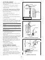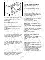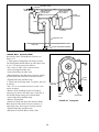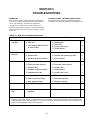
1
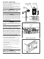
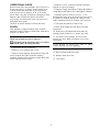
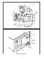
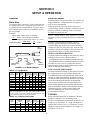
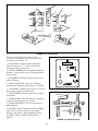
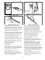
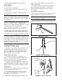
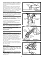
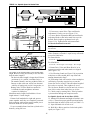
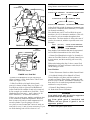
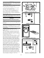
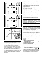
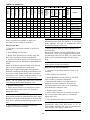
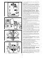
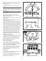
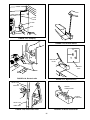
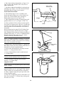
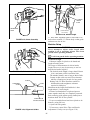
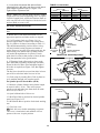
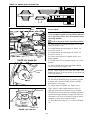
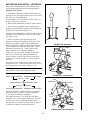
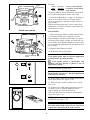
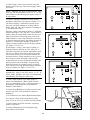
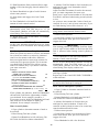
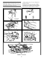
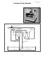
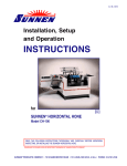
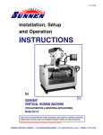
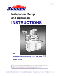
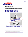
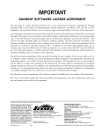
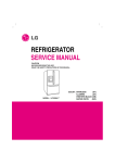
8. Loosen Stroke Adjustment Bolt and turn Stroke
Adjusting Knob so that index mark lines up with desired
stroke length on graduated scale (see Figure 3-60).
Tighten Stroke Adjustment Bolt.
TABLE 3-5, Overstroke
Stone Length
inches
millimeters
2-3/4 in.
70 mm
3-1/2 in.
89 mm
4-1/2 in.
115 mm
6 in.
152 mm
NOTE: Make sure you are using correct Cylinder
Length Scale for stone length being used. To replace
Cylinder Length Scale, turn Scale Retainer Knob so
scale can slide off to left. Replace with desired scale
and turn Knob to secure scale.
Top Overstroke
Setting
inches
millimeters
3/8 in.
9,5 mm
5/8 in.
16 mm
13/16 in.
21 mm
1-1/16 in.
27 mm
CYLINDER LENGTH
SCALE
Set Stroke Position/Overstroke
NOTE: Overstroke is amount that stone sticks out of
bore.
SCALE
RETAINER
KNOB
9. Rotate Drive Tube until Hone Head is in its
upper-most position and index marks are aligned.
10. Use Elevating Crank (see Figure 3-61) to
position engine block so stones will extend above
top of cylinder to be honed, according to Table 3-5.
This should automatically position stones so they
will not hit main bearing supports on bottom of
stroke. However, in some cases main guide may hit
main bearing web. Rotate hone by hand so that it
will stroke through bottom of cylinder. If main
guide does hit, remove that portion of shoe (bronze
strip) that protrudes below guide holder.
STROKE
ADJUSTMENT
BOLT
STROKE
ADJUSTING
KNOB
(GUARD REMOVED
FOR CLARITY)
FIGURE 3-60, Stroke Adjustment
INDEX MARKS
11. If Elevating Crank will not raise or lower workpiece sufficiently to produce required top overstroke,
loosen Set Screw in Drive Tube and adjust length of
drive tube as required (see Figure 3-62); then tighten
set screw.
The Set Screw should be screwed into hole in lower
part of drive tub when index lines are in line.
12. Check setup by rotating Drive Tube by hand to
cycle machine through one complete stroke.
(GUARD REMOVED
FOR CLARITY
Set Spindle Speed & Stroke Rate (SPM)
FIGURE 3-61, Stroke Position
13. Measure cylinder diameter and cylinder length
to nearest l mm (1/16 in.). Then select proper
spindle speed and stroke rate from chart on inside
belt cover (see Table 3-7).
ELEVATING
CRANK
14. Open left-hand side of belt cover.
15. Shift Drive Belt to position for desired spindle
speed (see Figure 3-63).
16. Shift Stroke Belt to position for desired stroking
rate.
17. Close belt cover.
Lock belt cover before attempting to operate.
This cover is interlocked, and machine will not
operate with cover in open position.
OVERSTROKE
FIGURE 3-62, Overstroke
28