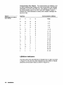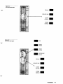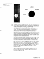
1
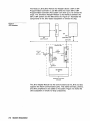
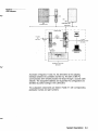
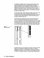
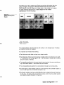
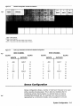
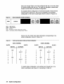
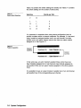
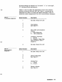
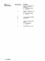
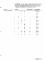
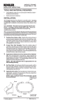
Modicon
J81015812Remote l/O Adapter
Installationand Operation Guide
PI-J81 O-002
Rev. C
n Merlin Gerin n Modicon n Square D W Telemecanique
Modicon 581 O/J81 2
Remote I/O Adapter Installation
cr’ and Operation Guide
PI-J81 O-002 Rev. C
November, 1991
MODICON, Inc., Industrial Automation Systems
One High Street
North Andover, Massachusetts 01845
Subject
Instructions for installing and operating the J81O/J81? Remote I/O
Adapter for use with a 584 or 984 Programmable Controller and 800
Series I/O Modules.
July, 1989
Modicon, Inc., Industrial Automation Systems
One High Street
North Andover, MA 01845
Preface
The information in this document is subject to change without notice
and should not be construed as a commitment by Modicon, Inc.,
industrial Automation Systems. Modicon, Inc., assumes no responsibility for any errors that may appear in this document. No part of
this document may be reproduced in any form without the express
written permission of Modicon, Inc., Industrial Automation Systems. All
rights reserved.
The following are trademarks of Modicon, Inc.:
Modicon
Micro 84
Modbus
Modvue
Modway
184
384
484
584
584M
584L
884
984
P180
P190
This guide contains instructions for installing and operating the
J81 O/J81 2 Remote I/O Adapter to allow remote I/O communications to
exist between a 584 or 984 Programmable Controller and 800 Series
I/O. Chapter 1 is an introduction to the remote I/O system. Chapter 2
covers system description. Chapter 3 provides instructions for
configuring the system. Chapter 4 contains installation instructions.
Chapter 5 details confidence tests. Appendix A lists the error codes and
their definitions. Appendix B is a specifications table. Appendix C
contains a configuration procedure.
0 Copyright 1989, Modicon, Inc.
Printed in U.S.A.
. ..
III
List of Related
Publications
Use the followingpublicationsin conjunctionwith this guide:
ML-584A-000
584 Programmable Controller User’s Manual
ML-A584USE
584 Programmable ControllerASCII Programming
Guide
ML-584RUSE
584 Programmable Controller Remote I/O
Processing Guide
PI-584B-001
584 Programmable Controller Remote I/O
Installationand TroubleshootingGuide
PI-584M-001
584M ProgrammableController System Planning
and Installation Guide
PI-584L-001
584L ProgrammableController System Planning
and Installation Guide
PI-884A-002
884 Programmable Controller System Planning
and InstallationGuide
PI-984A-004
984 Programmable Controller, ProgrammingGuide
PI-984A-003
984 Programmable Controller System Planning
and InstallationGuide
Chapter
1
Introduction
I-1
Chapter
2
System
Description
Chapter
3
System
Configuration
291
3-l
Standard Configuration
3-4
Dense Configuration
3-5
Chapter
4
Installation
4= 3
J8lO/J812 Remote I/O Adapter 4-2
Switchpack Switches 4-2
Drop Address 4-5
Communication Port Address 4-6
LED/Error Indicators 4-6
Front Panel Keyswitch 4-8
Cable Connections
4-10
Chapter
5
Confidence
Tests
5-q
Power-up Confidence Test 5-2
Confidence Tests 5-2
On-line Confidence Tests 5-2
Test Modes 5-3
Repeat Test Mode 5-3
Single-Step Test Mode 5-4
Appendix
A
Error Codes
Appendix
B
Specifications
Appendix
C
Configuration
A-3
&I
Procedure
C=Y
TABLE OF CONTENTS
Table
of Contents
(cont.1
figures
2-l
2-2
J810 Subsystem
J812 Subsystem
2-2
2-3
3-l
3-2
3-3
3-4
3-5
3-6
3-7
Switchpack Switches 3-2
Module Addressing Block Diagram
3-3
Standard Configuration of Multi-word Modules
3-5
Traffic Cop Information for Multi-word Standard Configuration
3-5
Dense Configuration of Multi-word Modules
3-6
Traffic Cop Information for Multi-word Dense Configuration
3-6
Position Cooperation
3-8
4-l
4-2
4-3
4-4
4-5
Switchpack Switches 4-2
J810 Front Panel LED’s
4-7
J812 Front Panel LED’s
4-7
Front Panel Keyswitch 4-9
Front Panel BNC Connector
4-10
A-l
A-2
LED/Error Indicators A-2
Test Error Codes A-2
Tables
2-l
Subsystem Components and Corresponding Publications
3-1
3-2
Dense Configuration
3-7
Density Switch Selections
4-l
4-2
4-3
4-4
4-5
Top Switchpack Assignments
4-3
Bottom Switchpack Assignments
4-3
J812 Communication Switchpack Assignments
4-4
Drop Address Switch Settings 4-5
Communication Port Address Switch Settings 4-6
TABLE OF CONTENTS
3-8
2-4
Chapter *
Introduction
This chapter provides an introduction to the J81O/J812
subsystem of a 584 or 984 Programmable Controller
system. The features of the systems are listed.
Introduction
1-1
The J81 O/J812 Remote I/O Adapter is designed to allow remote I/O
communicationsbetween a 584 or 984 Programmable Controller and
800 Series I/O modules. This provides the capabilitiesof a large
controllerwith the advantages of the compact and easy-to-install 800
Series I/O modules which can go in either rack- or panel-mounted
housings.
The 584/800 and 984/800 Remote I/O Systems feature the following:
* The 800 Series I/O has a higher density than 200 Series I/O normally
used with the 584 Controller.
. Each J8lO/J812 supports 256 input points and 256 output points.
. The J81 O/J812 and the P800 Power Supply plug directly into an 800
Series mainframe housing, providingan integrated package.
. The drop address is selected by setting the switches in the J8lO/J812
Adapter.
. LED/Error indicatorson the front panel of the adapter indicate certain
J8lO/J812 status when on; if flashing, they indicate a hardware failure.
. The controllercommunicationstimeout period is selectable: 300 or 1200
milliseconds.This allows support of the 584/J211 redundancy system,
as applicable.
. The J8lO/J812 executes confidence tests on power-up and in repeat
and single-step test modes.
. The J8lO/J812 executes on-line confidence tests.
. The J81O/J812 Adapter can be added to an existing 584 PC system with
no software changes to the 584 Controller or other drops on the line.
. The 584 or 984 Controller can also use 200 Series I/O modules
simultaneously,at a different drop. The 984 Controller can use 500
Series I/O as well.
. The J81O/J812 periodicallysamples configured I/O modules, providing
the most recent data from the input modules and the most recent health
informationfor input and output modules.
System
Chapter 2
Description
A description of the components of the 584/800 and
984/800 remote I/O systems is in this chapter along with
the titles and publication part numbers for all related
manuals.
System Description
2-1
The Modicon J81O/J812 Remote I/O Adapter allows a 584 or 984
Programmable Controller to use 800 series I/O. Each 584 or 984
Programmable Controller (PC) system can drive up to 16 remote I/O
drops. The J81O/J812 Adapter Module is the interface between the
584 or 984 system and the 800 series I/O. Figure 2-1 illustrates the
components of the J810 based subsystem or remote I/O drop.
-
Figure 2-1
J810 Subsystem
+
J200
[‘I
OR
984
584
CONTROLLER
CONTROLLER
NETWORK
4
b
r----
115 VAC
OR
220 VAC
--SUBSYSTEM
-1
D.C.
POWER
/
I
P800
POWER
SUPPLY
I
I
L+
D.C.
POWER
FROM/TO FACTORY
DEVICES
The J812 Adapter Module has the same functions as the J810 and also
supports two ASCII communication ports. This allows terminals, printers,
and other peripherals to be added to the system. Figure 2-2 shows the
J812 subsystem or remote I/O drop components.
2-2
System Description
Figure 2-2
5812 Subsystem
115 VAC
TERMINAL
FROM/TO FACTORY
DEVICES
As shown in Figures 2-1 and 2-2, the J81O/J812 is the adapting
interface between the controller and the I/O; The 584 or 984 PC
communicates with remotely located I/O drops through a coaxial cable
network. The subsystem address and supported I/O configuration are
identified by switch settings in the J81O/J812.
The subsystem components are listed in Table 2-1 with corresponding
publication names and part numbers.
Table 2-1
Subsystem Components
Equipment
and Corresponding
Publications
Publication Name
Publication
Part Number
Select One 0
584A, 584M, 584L, or
984 Programmable
Controller
0 584 Programmable Controller Remote I/O Processing
Guide
ML-584R-USE
cl 584 Programmable Controller Remote I/O Installation
and TroubleshootingGuide
PI-584B-001
Select One 0
cl 584M Programmable Controller System Planning and
PI-584M-001
InstallationGuide
cl 584L ProgrammableController System Planning and
PI-584L-001
Installation Guide
cl 584 Programmable Controller User’s Manual
cl 984 Programmable Controller System Planning and
ML-584A-000
PI-984A-003
InstallationGuide
Select One Cl
J200 Remote I/O
Interface (with 584
PC only)
0 584 Programmable Controller Remote I/O Processing
Guide
ML-584R-USE
cl 584 Programmable Controller Remote I/O Installation
and TroubleshootingGuide
PI-5848-001
H819-103 and/or
H827-103 Module
Housing(s)
884 Programmable Controller System Planning and
Installation Guide
PI-884A-002
J81 O/J812 Remote
I/O Adapter
J81 O/J812 Remote I/O Adapter Installationand
Operation Guide
PI-J81O-002
584 Programmable Controller ASCII Programming
Guide
ML-A584-USE
P800 Power Supply
Module
884 Programmable Controller System Planning and
InstallationGuide
PI-884A-002
800 Series I/O
Modules
884 Programmable Controller System Planning and
InstallationGuide
PI-884A-002
884 ProgrammableController System Planning and
InstallationGuide
PI-884A-002
BNC connector to F
coaxial cable
Taps and splitters
W801 and W802 or
W808 cables
2-4
System Description
System
-_
-_
Chapter 3
Configuration
This chapter covers general configuration information and
instructions along with more specific details for the
type(s)
of configuration chosen: standard slot and/or
dense slot. A configuration procedure can be found in
Appendix C. This appendix provides a summary of the
instructions contained in this chapter and in Chapter 4 of
this document.
The 584/800 or 984/800 remote I/O system consists primarilyof the
J81O/J812 Adapter Module and various 800 Series I/O Modules. The
physical configurationof each subsystem determines the logical
configurationwhich needs to be identified in the 584 or 984 Traffic Cop
Table for the specified channels. The mainframe housing for each
subsystem must contain a power supply in the first slot. The J81O/J812
Module is mounted in slots two and three in the mainframe housing, to
the right of the power supply.
All I/O modules reside in slots followingthe adapter module and in slots
of connected module housings.The physical configurationor slot
number for each module is determined solely by its position in the chain
of module housings. Switch settings do not determine individualslot
numbers (as with 200 series I/O).
A switch setting does determine the size of the housings being used.
There are two sizes of 800 Series module housings: 19-inch and
27-inch. It is importantfor the J81O/J812 to know the size of the housing
so that all slots are read. This is done by setting switch six in the bottom
switchpack inside the rear panel of the J81O/J812 Adapter (see Figure
3-l). To select 19-inch housings, seven slots each, flip the switch to the
left: for 27-inch housings, eleven slots each, flip the switch to the right.
Figure 3-l
Switchpack Switches
By selecting the size of the housings, the maximum number of housings
allowed in the subsystem is determined since there is a maximum
configurationof 32 slots. This configurationis obtained by using all the
available slots starting with rack one, slot four and numberingthe slots 1
to 16 then 1 to 16 again. One set of 16 can be used for input only and
3-2
System Configuration
the other set of 16 for output only. Each set can then be broken into two
groups of eight, one group for the odd channel and one group for the
even channel. This can help you to keep track of the inputs and outputs
for each channel. Figure 3-2 is a block diagram of the module
addressing of 1g-inch housings.
Figure 3-2.
Module Addressing
Diagram
Block
I PSOO I
J810/5812
ODD = Odd Channel
EVEN = Even Channel
POS = Position
The module address, determined by the slot number, is not changed even if modules
are inserted, removed, or replaced.
It is important to remember the following:
Each slot can contain either an input or an output module.
Each channel is broken up into two groups of eight positions numbered one to eight
(l-8) followed by one to eight again (i-8). The first group for inputs and the second
group for outputs, if desired.
Corresponding positions for the same channel cannot contain the same module type,
e.g., odd channel position 1 cannot both be input modules.
The corresponding slot position for a bidirectional module must remain empty.
An 8-bit input or output module counts as a full 16-bit word; the controller reads it as
the low order byte of the 16-bit 984 word (bits 9-16).
Multi-word modules must be counted differentlywhen configuringthe point maximum
for the drop. The total number of points the modules control must be added together
when determining the 256 point I/O maximum.
System Configuration
3-3
.
Multi-word modules must be counted differently when configuring the
point maximum. Multi-word modules are modules with more than 16 bits
each and represent a number of 16-bit words. Each word, 16 bits, not
just each module must be counted when determining the 256 point I/O
maximum.
Standard configuration is best for single-word modules since the I/O
position is the same as the physical slot location. Dense configuration
allows multi-word modules to be used without wasting housing space. A
combination of standard and dense configuration is possible.
The configuration information corresponding to the physical configuration
must be entered in the controller Traffic Cop, whether using standard
configuration, dense configuration, or both.
Standard
Configuration
Standard configuration is used for single-word modules since the I/O
position is the same as the physical slot location. This allows a visual
mapping of the 584 or 984 Traffic Cop information to the housing slot
location. Figure 3-2 is an example single-word standard configuration in
a block format.
Standard configuration is selected by setting switches two to five in the
bottom switchpack to the left. The switchpacks are located in the
housing backplane as shown in Figure 3-1.
Multi-word modules can also be configured this way. However, you need
to consider that although the module occupies only one physical slot
location, the slot(s) following the module must remain empty. For
example, a four-word input module occupies one physical slot but uses
four positions of a channel. For this reason, the three slots following the
input module must remain empty to allow for the I/O positions. The slots
for this four-word input module are counted as if there are actually four
one-word input modules. See Figure 3-3. Figure 3-4 is the corresponding T
‘ raffic Cop Table information.
Housing space is wasted if standard configuration is chosen with
multi-word modules and it is therefore advisable to choose dense
configuration (see Dense Configuration in this chapter).
If using a combination of standard and dense configuration, the
standardly configured modules must follow the dense configuration.
Standard Configuration
Figure 3-3
ODD
EVEN
AIN
AOUT
=
=
=
=
Odd
Even
Four
Four
of Multi-word Modules
Channel
Channel
word, one slot analog input module
word, one slot analog output module
Traffic Cop Information for Multi-word Standard Configuration
Figure 3-4
EVENCHANNEL
ODDCHANNEL
SLOTS
SLOTS
1
INPUTS
OUTPUTS
AIN
AOUT
9
SLOTS
INPUTS
OUTPUTS
AIN
AOUT
9
4
i
I
12
11
10
AIN
AOUT
13
I
16
15
14
1
2
2
1.
3
4
I
5
AIN
6
8
7
SLOTS
I
12
11
10
3
AOUT
13
5
I
16
15
14
6
8
7
I
Dense Configuration
Dense configuration allows a number of multi-word modules to be used
without wasting housing space. This is done by modifying the l/O
numbering scheme. Each position in a channel does not need a
corresponding physical slot. For example, four channel positions,
represented by a multi-word module, can be assigned to one slot.
System Configuration
3-5
Slots one through fifteen can all be configuredthis way or as many slots
as needed starting with slot one. The slots not allocated as dense slots
remain one-word slots for standard configuration.
An example dense configurationof multi-wordmodules in block format
can be found in Figure 3-5. This can be compared to the standard
configurationof the same module types which is shown in Figure 3-3.
Dense Configuration of Multi-word Modules
Figure 3-5
ODD = Odd Channel
EVEN = Even Channel
POS = Position
AIN = four-word, one-slot analog input module
AOUT = four-word, one-slot analog output module
Figure 3-6 is the Traffic Cop Table informationcorrespondingto the
dense configurationshown in Figure 3-5.
Figure 3-6
Traffic Cop Information for Multi-word Dense Configuration
ODD CHANNEL
EVEN CHANNEL
SLOTS
1
SLOTS
SLOTS
INPUTS
OUTPUTS
AIN
i
9
1
AOUT
10
2
I
13
12
11
4
3
5
AOUT
14
SLOTS
INPUTS
OUTPUTS
AIN
4
9
AOUT
10
3
4
2
5
I
AIN
7
8
6
I
15
7
16
8
6
I
AIN
I
I
AOUT
13
12
11
14
15
16
To select dense configuration,set switches two through five in the
bottom switchpack(see Figure 3-l) accordingto Table 3--l.
3-6
System Configuration
Table 3-1
Switches
Slots 1 through...
Dense Configuration
2
3
9
5
R
L
L
L
1
L
R
L
L
2
R
R
L
L
3
L
L
R
L
4
R
L
R
L
5
L
R
R
L
6
R
R
R
L
7
L
L
L
R
8
R
L
L
R
9
L
R
L
R
IO
R
R
L
R
11
L
L
R
R
12
R
L
R
R
13
L
R
R
R
14
R
R
R
R
15
R means flip the switch to the right; L is flip the switch to the left.
Switches seven and eight of the bottom switchpack must also be set
when using the dense mode of configuration. These switches are used
to select the density of words per physical slot. For example, if a series
of 32-bit multi-word modules is being used, it is necessary to configure a
density of two words for each slot.
If a mix of two-word and four-word modules is being used, the density of
words per slot is two, representing the minimum density in the group.
The number of dense slots needed at this density is determined by
taking the total number of words and dividing it by the minimum
multi-word density. For example, if a mix of three two-word and two
four-word modules is used, the number of dense slots is seven:
6 + 8
(3 X 2 words) + (2 X 4 words) = (3 X 2) + (2 X 4) =-=-=
minimum density of 2
2
2
14
2
7,
System Configuration
3-7
Table 3-2 contains the switch settings for density and Table 3-1 contains
the switch settings for the number of dense slots.
Table 3-2
Density Switch Selections
Switches
Words per Slot
L
L
2
R
L
4
L
R
8
R
R
16
It is importantto remember when using dense configurationthat the
position numbers within a channel cooperate. For example, if a two-word
output module is assigned positionone in an odd channel, the other
positionone in the same channel cannot also have an output module
assigned to it. See Figure 3-7.
Figure 3-7
Position Cooperation
In the same way, an even channel’s positionthree cannot have two
input modules assigned to it; it can have an input module assigned to
one positionthree and an output module assigned to the other position
three.
It is possible to have an output module in positiontwo of an odd channel
and positiontwo of the correspondingeven channel.
3-8
System Configuration
w
Chapter 4
Installation
This chapter provides instructions for installing a
J81O/J812 Remote I/O Adapter and making the appropriate
cable connections. For information regarding 584 PC
installation and the remote l/O system consult the
following:
l
l
l
584 Programmable Controller System Planning and
Installation Guide
584 Programmable Controller Remote I/O Processing
Manual
584 Programmable Controller Remote I/O Installation and
Troubleshooting Guide
984 installation instructions can be found in the 984
Programmable Controller System Planning and Installation
Guide. Installation instructions for the 800 Series I/O
Modules and Housings can be found in the 884
.Programmable Controller System Planning and Installation
Guide.
Installation
4-1
581 O/J81 2 Remote
II0 Adapter
The J81O/J812 Remote I/O Adapter is inserted into the second slot in
the mainframe housing, to the right of the P800 Power Supply. Before
inserting the adapter, it is necessary to set the switches inside the back
of the J81OIJ812.
)
CAUTION Power must be OFF when inserting or removing the
581 O/J812 Adapter.
Switchpack
Switches
There are two switchpacks located inside the back of every J810 and
J812 Adapter. The top switchpack is used to set the JSlO/J812
configuration and drop address as outlined in Drop Address in this
chapter. The bottom switchpack is used to set the I/O configuration as
outlined in Dense Configuration in Chapter 3.
The J812 also has a third switchpack located inside the rear panel. This
switchpack is used to set the address and configuration of the
communication devices attached to the J812. See Figure 4-1.
Figure 4-1
Switchpack
Switches
J812
SWITCHPACK
TOP
SWITCHPACK
BOTTOM
SWITCHPACK
*
4-2
Installation
All switch settings are referred to as “to the left”, “L”, or “to the right”,
“R”, left being off and right being on.
Tables 4-l and 4-2 outline the assignments of each of the switches
common to both the J810 and J812, with Table 4-l covering the top
switchpack and Table 4-2 covering the bottom switchpack. Table 4-3
outlines the switch assignments for the J812 communication switchpack.
Table 4-1
lop Switchpack Assignments
Switch Number
1
2
3
4
5
Table 4-2
Bottom Switchpack
Assignments
Description
Not Used. Keep to the Left.
Drop Address
See Table 4-4.
6
584 or 984 Communications
Timeout
L = 300 milliseconds
R = 1200 milliseconds
7
Confidence Test Mode
L = Normal
R = Repeat or Single Step
(See Confidence Tests in
Chapter 5)
8
Not Used. Keep to the Left.
Switch Number
Description
1
Not Used. Keep to the Left.
2
3
4
5
Dense Configuration
See Table 3-1.
6
Housing Size
L = 19-inch
R = 27-inch
7
8
Density of Words
See Table 3-2.
Installation
4-3
Table 4-3
J812 Communication
Switchpack Assignments
Switch Number
1
RS-232-C Handshake for
Bottom Port
L = Data Terminal Ready
R = X on/X off
2
RS-232-C Handshake for Top
Port
L = Data Terminal Ready
R = X on/X off
3
4
5
6
4-4
Installation
Description
Communication Port Address
See Table 4-5.
7
Continuous Confidence Test
Mode
L = Local Diagnostic
R = On-Line
8
Not Used. Keep to th:2 Left.
Drop Address
The drop address is set by setting switches two through
five in the top switchpack according to Table 4-4. The drop address
refers to the channels of I/O. For example, the third drop, set as L Fi L
L, represents the drop address for channels five and six.
Table 4-4
Drop Address Switch Settings
Switches
Drop Number
Drop Address
Channels
2
3
!I
5
L
L
L
L
1
1, 2
R
L
L
L
2
3, 4
L
R
L
L
3
5, 6
R
R
L
L
4
7, 8
L
L
R
L
5
9, 10
R
L
R
L
6
11,12
L
R
R
L
7
13,14
R
R
R
L
8
15,16
L
L
L
R
9
17,18
R
L
L
R
10
19,20
L
R
L
R
11
21, 22
R
R
L
R
12
23,24
L
L
R
R
13
25,26
R
L
R
R
14
27,28
L
R
R
R
15
29,30
R
R
R
R
16
31, 32
Installation
4-5
The communication port address is set
Communication Port Address
by setting switches three through six in the communication port address
switchpack in the J812 (see Table 4-5). This address is used to identify
the communication ports on the J812. Each J812 Adapter is given a
different pair of port addresses to identify which adapter messages are
sent to or from.
Table 4-5
Communication Port Address
Switch Settings
Communication
Switches
Ports
3
4
5
6
R
R
R
R
1,2
L
R
R
R
3, 4
R
L
R
R
5, 6
L
L
R
R
7, 8
R
R
L
R
9, 10
L
R
L
R
11,12
R
L
L
R
13,14
L
L
L
R
15, 16
R
R
R
L
17, 18
L
R
R
L
19,20
R
L
R
L
21,22
L
L
R
L
23, 24
R
R
L
L
25, 26
L
R
L
L
27, 28
R
L
L
L
29, 30
L
L
L
L
31, 32
LED/Error
Address
Indicators
The front panel of the J810 Remote I/O Adapter has six LED’s as shown
in Figure 4-2. The J812 has these indicators plus four others to indicate
peripheral communication status as shown in Figure 4-3.
4-6
Installation
Figure 4-2
5810 Front Panel LED’s
READY
CONFIG
OK
COMM
ACTIVE
COMM
ERROR
Figure 4-3
J812 Front Panel LED’s
COMM
ERROR
installation
4-7
The followingis a list of the LED’s and what they indicate when ON:
584/984 Communications
READY
The J81 O/J812 is healthy and ready to
communicatewith the 584 or 984.
CONFIG OK
The J81 O/J812 configuration
completed successfully.
COMM ACTIVE
The 584 or 984 is controllingthe I/O
modules. The J81 O/J812 is receiving
read/write commands from the 584 or
984.
COMM ERROR
Communicationserror.
J812 ASCII Communications
RUN
ASCII CPU and memory are healthy.
COMM ERROR
584 or 984 communicationerror.
COMM ACTIVE
Communicationactivity with the 584 or
984.
INTERFACE ERROR
Serial port interface error.
Power Supply
Power received by J81O/J812.
POWER
Modem
CARRIER DETECT
The modem is ready, receiving
messages.
Four of these LED’s, the 584/984 communicationsLED’s, are also used
to indicate confidence test errors. Upon detecting an error, the
J81O/J812 ceases normal operation then flashes a combinationof the
four LED’s to indicate which test detected the error. Appendix A covers
all the possible error codes and their definitions.
Front Panel
Keyswitch
Located on the front panel of the J81 O/J812 is a two-positionkeyswitch
with the labels LEARN and RUN. See Figure 4-4. This keyswitch is used
to select either LEARN or RUN mode. It is also used to select repeat or
single step test mode if test mode is chosen using switch seven in the
top switchpack(see Chapter 5).
4-8
Installation
Figure 4-4
Front Panel Keyswitch
MODE
RUN
LEARN
WARNING
When in LEARN mode, the J81O/J812 writes zeros to all
output modules. Equipment which is sensitive to zero data should
be disconnected prior to switching to LEARN mode.
The LEARN mode should be selected upon the initial power-up of a
system, when changes have been made to any of the switchpack
switches, and/or when I/O module changes have been made.
When the keyswitch is turned to LEARN, all the 800 Series I/O modules
present are scanned. The J81O/J812 reads the module type and size,
validating the physical I/O configuration. The adapter learns the current
configuration from the switchpacks as well.
The J81O/J812 Adapter maintains communications with the 584 or 984
Controller but does not control the I/O modules with 584 or 984 data.
The J81O/J812 Adapter also reports bad health for all module slots.
If the configuration is valid, the CONFIG OK LED is on. If the CONFIG
OK LED does not come on, one or more modules are in conflicting
positions. A quick examination of MODULE ACTIVE lights determines
which modules, if any, are conflicting. The MODULE ACTIVE light on a
module is off if the module is conflicting and flashing on all nonconflicting modules.
After the configuration has been learned and validated, place the
keyswitch in the RUN position. The 584 or 984 Controller is now
controlling the 800 Series I/O
Installation
4-9
NOTE If any changes are made in the switchpacks or if any I/O
modules have been replaced or moved, it is very important that the
keyswitch be placed in the LEARN position until the configuration is
learned and validated. If this is not done, the changes are not
acknowledged; it is assumed that the previous configuration is still
relevant and it is still used.
Cable
Connections
The 584 Programmable Controller is connected to the J200 Remote I/O
Interface via the cable that comes with the J200. The J200 Interface is
connected to its remote I/O drops via a coaxial cable. In this case, a
BNC to F coaxial cable is used. This same type cable is used to connect
the 984 PC directly to its remote I/O drops.
Appropriate connections must be made from the coaxial cable using
taps and splitters to connect it to the BNC connector on the J81O/J812’s
front panel (see Figure 4-5). A graphic representation of these
connections can be found in Figures 2-1 and 2-2 in Chapter 2.
Figure 4-5
Front Panel BNC Connector
BNC TO F COAXIAL
CABLE
!
4-10
Installation
BNC CONNECTOR
Peripheral devices can be connected to ports 1 and 2 on the J812 front
panel. These RS-232-C ports have the following pinouts:
Pin
1
2
3
4
5
6
7
20
Signal Name
Protective (earth) Ground
Transmit Data
Receive Data
Request to Send
Clear to Send
Data Set Ready
Signal Ground
Data Terminal Ready
The module housings themselves are interconnected by an AS-W801OXX cable and an AS-W802-OXX or AS-W808-00X cable. The W801
cable is a 37-pin flat bus signal cable and the W802 and W808 cables
are 15pin power cables. The W801 and W802 cables come in one foot,
six foot, and twelve foot lengths and the W808 cable comes in 1.5 foot
and five foot lengths. For specific installation instructions, see the 884
Programmable Controller System Planning and Installation Guide.
Installation
4-11
Chapter 5
Confidence
Tests
This chapter describes the various tests which the
J810/5812 Remote I/O Adapter is capable of performing.
These tests include the power-up confidence test, the
on-line confidence tests, and the repeat and single-step
test mode confidence tests. If any of the tests fail, an
error code is flashed in the LED%. The error codes are
given in Appendix A.
Confidence Tests
5-l
Power-up
Confidence Test
The main purpose of the power-up confidence test is checking the
J81O/J812 hardware to determine whether or not the adapter is ready for
proper operation. Included in this test are the following, in order of
execution:
1
2
3
4
5
6
7
8
9
10
11
12
LED test
PROM test
RAM data test
Digital loop test
Analog loop test
Switched RAM test
RAM address test
Switchpack present test
EEPROM test
Port test
interrupt test
Real time clock test
If all the tests pass, the READY LED comes on and operations can
proceed. If an error is detected, the power-up confidence test retains
control, thereby preventing the use of defective equipment. The
appropriate error code is flashed in the LED’s (see Appendix A) and a
power reset is required to restart.
Confidence
Tests
Following the power-up confidence test, there are two selectable tests
and the on-line confidence tests. With switch seven in the top
switchpack set to the left and the LEARN/RUN keyswitch in the RUN
position, only the on-line confidence tests are performed. The repeat or
single-step test modes of the confidence tests are selected by setting
switch seven in the top switchpack to the right.
On-line
Confidence
Tests
The on-line confidence tests detect hardware failures in a running
system. These tests are important since, without them, a hardware
failure occurring after power-up could go undetected and influence
system operation. This is especially important if a system is running for
several months without being shut off and restarted.
5-2
Confidence Tests
The on-line confidence tests consist of the following:
.
RAM data and address tests
l
PROM test
.
EEPROM test
.
Switched RAM tests
.
Switchpack image test
l
Clock ticking test
l
Modem Watchdog test
If an error is detected, the LED’s flash the appropriate error code, the
J81O/J812 Adapter ceases operation, and all outputs are driven to the
safe state.
Test Modes
The confidence tests can be invoked in either of two test modes. These
tests are used primarily for bench testing or intermittent troubleshooting.
If a test mode is selected, the tests are executed in the following order:
1
2
3
4
5
6
7
8
9
10
11
12
LED test (once initially)
PROM* test
Switched RAM tests
RAM data and address tests
EEPROM test
Switchpack image test
Modem Watchdog
Port test
Switchpack present test
Interrupt test
Real time clock test
Digital loop test
Analog loop test
The test modes are controlled by switch seven in the top switchpack and
by the J81O/J812’s front panel LEARN/RUN keyswitch.
Repeat Test Mode Repeat test mode allows the confidence tests to be
executed repeatedly in sequence. If all the tests pass, the tests are
executed again in sequence. If an error is detected, the LED’s flash the
appropriate error code.
To select this test mode, set switch seven in the top switchpack to the
right and place the LEARN/RUN keyswitch in the RUN position for
power-up.
Confidence Tests
5-3
Single-Step Test Mode Unlike repeat test mode, single-step test mode
must be prompted to execute the next sequential test. In single-step test
mode, the confidence tests are executed in sequence yet each individual
test is repeated until the LEARN/RUN keyswitch is either changed from
LEARN to RUN or from RUN to LEARN. At this point, the next test in
the sequence is performed until the keyswitch is changed again.
To select single-step test mode, set switch seven in the top switchpack
to the right and place the LEARN/RUN keyswitch in the LEARN position
initially.
5-4
Confidence Tests
W
Appendix A
Error Codes
If an error is detected in any of the confidence tests, an
error code flashes in the four LED’s on the front panel of
the J81O/J812 Adapter (see Figure A-l). This appendix
contains a graphic representation of the tests and the
error codes (see Figure A-2).
A power reset is required to restart the J810/5812. If this
fails to correct the error, replace the JSlO/J812 Adapter.
Error Codes
A-l
Figure A-l
LED/Error Indicators
READY
CONFIG
OK
COMM
ACTIVE
COMM
ERROR
Figure A-2
Test Error Codes
TESTS b
v LED’S
u
READY
CONFIG
OK I1
COMM
ACTIVE
COMM
ERROR
COMM
ACTIVE
COMM
ERROR
0
u
n
I[
r[
uuuu
A-2
Error Codes
0
0
u
Appendix 6
Specifications
HUMIDITY
0 - 95% non-condensing
SHOCK
10 G, peak l/2 sine
VIBRATION
.005 in. D.A., sine from 5 - 50 Hz
.625 G, sine from 50 - 500 Hz
DIMENSIONS
(WxHxD)
3.53 in. x 10.47 in. x 8.25 in.
(8.97 cm. x 26.59 cm. x 20.95 cm.)
WEIGHT
5 Ibs. (2.25 kg.)
OPERATING
TEMPERATURE
0” to 60” C
POWER
REQUIREMENTS
From the P800-003
Power Supply
Voltage
Current
+5
5000 mAmps (J810)
7250 mAmps (J812)
-5
100 mAmps
+12
100 mAmps
-12
75 mAmps
Specifications
B-l
w
;.
i
Configuration
i
Appendix C
Procedure
When setting up your 584/800 or 984/800 Remote I/O System, your 584
or 984 Programmable Controller must be configuredfollowingthe
standard configurationguidelines. Your J81 O/J812 Remote I/O Adapter
must be configured also. This is done by setting the appropriate
switches in the back of the J81O/J812 and by followingthe guidelines in
Chapters 3 and 4 of this guide.
The followingprocedure is designed to help you set up your
configuration.For details not contained here, reference the appropriate
chapter of this guide.
Step 1
Determine the types of modules being used and the number
of modules. Keep in mind the maximum number of 256 input
points and 256 output points.
Also, determine the size of the housings being used. Set
switch six in the bottom switchpackto the left for 19-inch
housings and to the right for 27-inch housings.
Step 2
Starting with a blank block diagram of your available I/O slot
locations, map out your l/O modules. Fill in the slots on the
block diagram, checking for conflictinginputs and/or outputs.
Follow the rules in Chapter 3 of this document.
Step 3
Select the type(s) of configurationbeing used. If using a
combinationof standard and dense configuration,determine
the number of dense slots needed and set switches two
through five in the bottom switchpackaccordingto
Table 3-l.
Step 4
Determine the density of words per slot and set switches
seven and eight in the bottom switchpackaccording to
Table 3:2.
Configuration Procedure
C-l
Step 5
Determine the drop number/address of your J81O/J812
Adapter and I/O. The drop number represents the positionof
your J81O/J812 system in the line communicatingwith a
particular 584 or 984 Controller. The drop address refers to
the I/O channels correspondingto a drop number. For
example, channels one and two are at drop number one.
Set switches two through five in the top switchpack
according to Table 4-4.
Step 6
Select a 584 or 984 communicationstimeout of either 300 or
1200 milliseconds.Set switch six in the top switchpackto
the left for 300 millisecondsor to the right for 1200
milliseconds.
Step 7
Select the confidence test mode using switch seven in the
top switchpack. Set the switch to the left for normal
confidence test mode. For repeat or single-step test mode,
set the switch to the right.
The front panel keyswitch is used to correctly operate the
repeat and single-step test modes. See Chapter 5.
C-2
Step 8
Select the RS-232-C handshake for each communication
port. Set switch one in the J812 switchpackfor the bottom
communicationport and switch two for the top port. Setting
either switch to the left is for Data Terminal Ready (DTR)
and to the right is for X on/X off.
Step 9
Determine the communicationdrop address of your J812
Remote I/O Adapter. This address is used to identify the
communicationports on the J812, thereby allowing you to
determine which adapter messages are sent to or from. To
select a communicationport address, set switches three
through six in the J812 communicationswitchpackaccording
to Table 4-5.
Step 10
Select the continuous confidence test mode. Set switch
seven in the J812 switchpackto the left for local diagnostic
test mode and to the right for on-line test mode.
Step 11
Set switches one and eight in the top switchpack, switch
one in the bottom switchpack, and switch eight in the J812
switchpackto the left.
Step 12
Insert the J81O/J812 Remote I/O Adapter firmly into the
mainframe housing in the slot to the immediate right of the
power supply.
Step 13
Turn the front panel keyswitchto the LEARN positionfor
power-up.
Step 14
Power-up the system and allow the J81 O/J812 Adapter to
learn the configuration.
Step 15
Turn the front panel keyswitch to the RUN position.
Configuration Procedure
Index
A
Addressing, 3-3
B
BNC Connector, 4-10
C
Cable Connections, 4-l 0, 4-l 1
Communication Port Address, 4-6
Components, System, 2-4
Confidence Tests, 5-2 to 5-4
Configuration, Physical, 3-2
Configuration Procedure, C-l
Connections, 4-l 0, 4-l 1
D
Dense Configuration, Multi-Word, 3-5, 3-6
Dense Configuration, Switch Settings, 3-7
Dense Slots, 3-7
Density, 3-7, 3-8
Drop Address, 4-5
Drop Number, 4-5
E
Error Codes, A-l, A-2
Error Indicators, 4-6 to 4-8, A-l, A-2
F
Front Panel BNC Connector, 4-10
Front Panel Keyswitch, 4-8 to 4-10
H
Housings, Size, 3-2
J
J810 Based Subsystem, 2-2
J812 Based Subsystem, 2-2
J8lO/J812 Remote I/O Adapter, 4-2
K
Keyswitch, 4-8 to 4-10
L
LEARN Mode, 4-8 to 4-10
LED Indicators, 4-6 to 4-8
LED/Error Indicators, A-l, A-2
M
Module Addressing, 3-3
Multi-word Modules, 3-4
0
On-Line Confidence Tests, 5-2, 5-3
P
Pinouts, 4-l 1
Position, 3-8
Power-up Confidence Test, 5-2
R
Repeat Test Mode, 5-3
RS-232-C Pinouts, 4-l 1
RUN Mode, 4-8 to 4-10
S
Single-Step Test Mode, 5-4
Single-Word Modules, 3-4
Slot Number, 3-2
Specifications, B-l
Standard Configuration, Multi-Word, 3-4
Standard Configuration, Single-Word, 3-4
Switchpack Assignments, 4-3, 4-4
Switchpacks, 3-2
Switchpack Switches, 4-2, 4-3
T
Test Modes, 5-3, 5-4
Traffic Cop, Multi-Word, 3-5, 3-6
INDEX
MODlCON
an AEG
Publications
Comment
Form
Document Part Number
PI-J81 O-007
company
Rev. C
Title J8101J812 Remote l/O Adapter lnstal.& Oper Guide
We are constantly striving to improve the content and usability of our technical documents. You can help us by answering the questions below and mailing this form to us. Also, if you find any errors or have any suggestions for improvement, please let us know.
HOW do you use this document?
0
Introduction to the product
0
Classroom resource
0
Self-study
0
Programming Procedures
0
Advanced programming techniques
0
Operating instructions
0
Reference
0
Other
Ordered from MODICON
How did you get this document?
0
Received with equipment
q
0
Received from Sales or Customer
Service Representative
0
Do not know
0
Other
Please rate this document.
Technical
Accuracy
Readability
Clarity
Examples
- Does the system work the way it is
described in the manual?
- Is the manual easy to read and
understand?
- Are the instructions easy to follow?
- Are the examples helpful and realistic?
Are there enough examples?
Organization
- Is the organization of the manual logical?
Is it easy to find what you are looking for?
Illustrations
- Are the illustrations clear and useful?
- What did you think of the layout,
Physical
Attractiveness
printing, binding, etc?
Are there any terms or concepts that are not defined clearly?
Y
0
N
0
Y
q
N
0
If so, what are they?
After reading this document, are you able to use the equipment?
What errors did you find in the manual? (Please include page numbers. Attach an extra sheet if necessary.)
Do you have any comments or suggestions?
Name
Street
Title
City
Dept./Mail Stop
State/Country
Company
Zip Code
Thank you for your help.
Telephone
NO POSTAGE
NECESSARY
IF MAILED
IN THE
UNITED STATES
BUSINESS
FIRST
Postage
CLASS
PERMIT
REPLY MAIL
NO. 234
ANDOVER,
MA
will be paid by addressee:
MODICON, Inc.
1 High Street
North Andover, MA 018459943
Attn: Technical Publications 7-2A
III
,,,,,,1ll,,l,,l,,l,l,l,l,l,,l,l,,,l,,l,,ll,l,,,ll
lUlODlCON
an AEG company
TO ORDER
BY PHONE,
CALL
l-800-468-5342
and ask
for an Order Entry Coordinator
Ship To: (if different):
Bill To:
Customer Contact
Name:
Document
Part Number
Telephone:
Date
Purchase Order No.
Description
Quantity
Unit Price
Total Price
Sub Total
Authorized Signature
Freight
Date
Total
Ordering
Instructions
Provide appropriate billing address and shipping address (if different from billing address).
Please provide a contact name and phone number in case we have
a auestion about your order.
Indicate your purchase order number and date. (You may prepay
by enclosing a check for the full amount.)
Give the part number, description, and quantity for each document
ordered.
Delivery
Unless otherwise specified, all orders are shipped best way surface,
F.O.S. Andover, MA (prepay and add if UPS surface, collect for truck
and air). If you specify insurance, you will be billed for these changes.
MODICON will not assume any liability in connection with the shipment nor shall the carrier be construed to be an agent of MODICON.
Payment
Terms are net 30 days from date of invoice. Unless otherwise stated,
partial shipments will generate partial invoices.
Prices
Prices are subject to change without notice. Individual prices can be
found in the Publications Catalog or obtained by calling an Order Entry
Coordinator at 1-800-466-5342.
Y
i
\<sz
’
=l
-
NO POSTAGE
NECESSARY
IF MAILED
IN THE
UNITED STATES
-1
-i
-!
BUSINESS
FIRST
Postage
CLASS
PERMIT
-1
-,
REPLY MAIL
NO. 234
ANDOVER,
MA
WIII be paid by addressee:
MODICON, inc.
1 High Street
North Andover, MA 018459943
Attn: Order Entry 3-28
III
~~~~~,III~~I~~I~,I~l~l‘I~I~~I,I,,~l~~I~~II~I,,,II
I
2’
I
k
I
i
Modloon, Square D and Tekmecamque are KC brand names from Schneider These p%doduasare sold in the US by Square D:
in Canada, Labn Amaca. Europe. AInca AsiaXwlflc and Mlddls East by Schnekder; I” Germany by AEG Schneider
Aufomat~~ I” Chma and Pewan Gun by Schneider Automation: m South Africa by ASA Systems Automation; in Austria by
till”0
Schne,der Automaf~on Inc.
One High Street
North Andover, MA 01645
Tel: (1) 978-794-0800
Fax: (1)
978-795-9400
Schneider Automatmn GmbH
Steinhwmer Strasse 117
O-63500 SeliQenStadt
Tel: (49) 6182 61-2564
Fax:
(49)
6182
81-P&l
Schneider Automat!on S.A.
245. Route de Lucioles-SW47
F-06903 Sophia-Antipolis Cede%
Tel: (33) 92 96 20 00
Fax: (33) 93 65 37 15