1
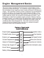
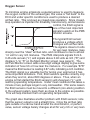
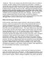
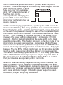
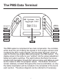
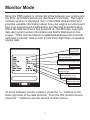
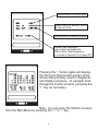
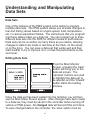
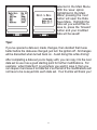
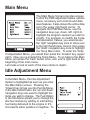
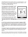
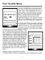
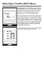
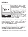
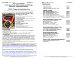
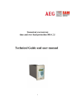
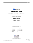
Revision 2.26.06
Table of Contents
Introduction
Engine Management Basics
The PMS Data Terminal
Monitor Mode
Understanding and Manipulating Data Sets
Main Menu
Idle Adjustment Menu
Part Throttle Menu & Single Cell Edit Mode
Wide Open Throttle Menu
N2O Menu
Options Menu
TPS Setup
Rev Limiter
Stand Alone Setup
Global Fuel Adjust
Wideband Selection
Sequential Timing/Fuel Menu
Accessory Port Settings
Temp Menu
Boost Menu
Accel Menu
02
03
07
08
10
12
12
15
17
18
19
19
20
20
21
21
22
23
26
27
28
Appendix A Self Diagnostics
Appendix B UEGO 2000
29
30
1
Introduction
Welcome to the Programmable Management System from EFI
Systems, Inc. The Programmable Management System, or PMS is
an engine control computer that you can use to tune your vehicle’s
engine management system to match the needs of your particular
engine setup. The PMS is a powerful system that offers the ability
to program in compensation for the addition of larger fuel injectors,
different camshaft profiles, forced induction, and even nitrous! With
the PMS, almost any engine combination can be safely tuned and
power output maximized.
How does it work?
The PMS unit monitors various input
sensors, reads the factory engine
management outputs, and then applies the
changes that you’ve programmed into it to
achieve proper tuning for your exact setup.
By including menus for idle, part throttle,
wide open throttle (WOT), temperature
compensations, and more, the PMS is truly a complete tuning system.
Many electronic tuning devices currently available are “band-aid”
solutions to a real engine management need. They offer limited tuning
- usually at WOT only. Custom chip tuning can work for one particular
setup, but if one component is changed, the chip must be burned all
over again and you will have to pay for the service all over again.
The PMS allows you to make changes again and again in real time!
With three separate data sets, you can try a new tuning strategy
without the risk of losing what you’ve already done.
2
Engine Management Basics
The term engine management has become commonplace in the
automotive world these days. In a nutshell, engine management is
the controlling of fuel, spark and other events involved in running your
engine. The controller of these events is referred to as the Electronic
Control Unit (ECU), the Powertrain Control Module (PCM), or the
Engine Control Module (ECM), depending on the manufacturer. No
matter what the name, the functions are basically the same. The
ECU takes in data from available engine sensors, follows a factory
installed program, and determines the appropriate outputs required
to make your engine run smoothly, efficiently and safely under all
conditions that it was designed for. The main concerns of most
modern ECUs are keeping fuel economy up, exhaust emission
production down and driveability smooth.
Engine Speed
Ignition Coil(s)
Throttle Position Sensor
Fuel Injectors
Engine Load
Idle Speed Control
Coolant Temperature
Emissions Devices
Intake Air Temperature
Transmission Controls
Exhaust Gas Oxygen (O2)
Malfunction Indication Lamp
Knock Sensor
Battery Voltage
3
Oxygen Sensor
To minimize engine emissions a special sensor is used to measure
the oxygen content of the exhaust gas; this value is "fed back" to the
ECU and under specific conditions is used to produce a desired
air/fuel ratio. This is known as closed-loop operation. Since closedloop operation is important for drivability, fuel economy, and emissions
control, the EGO signal is
one of the most important
signals to watch on the PMS
monitor screens.
The typical EGO sensor
produces a voltage which
changes with air/fuel ratio.
The signal is close to 0 volts
for very lean mixtures, rises
sharply near the “ideal” air/fuel ratio, and continues to rise to almost
1.0 volt for very rich mixtures. The PMS interprets signals from 00.46 volts as lean (”L”) and signals above 0.46 volts as rich (”R”) and
displays “L”or “R” on the Main Monitor screen (see page 9). The
Air/Fuel Monitor screen adds a two-digit voltage display to give some
indication of how rich or how lean the mixture is. For example “87R”
means the EGO sensor is reading 0.87 volts, indicating a rich condition.
The EGO signal is a valuable tool for tuning your engine but it has
some important limitations. First, EGO sensors operate correctly only
when they are hot, about 600 degrees or above. Thus, when an
engine is first started the EGO sensor(s) will show lean (”L”) until
reaching operating temperature. Under most conditions this takes a
minute or two; perhaps longer in very cold weather. If for some reason
the EGO sensors must be moved to a different (non-stock) postition
in the exhaust system, keep them as close to the engine as possible.
This will help maintain them at operating temperature.
The graph also illustrates another problem with EGO sensors; note
that the sensor output is not a straight line. Once the air/fuel ratio
gets outside of a narrow band around the stoichimetric, or perfect
value, sensor voltage barely changes at all for very rich or very lean
4
mixtures. This is one reason why the ECU does not try to achieve
a single, perfect voltage during closed loop operation. Instead, it
varies the fuel commands to switch the EGO voltage back and forth
around the desired value. EGO sensor output must be interpreted
in light of sensor quality and service life. Mass-produced EGO sensors
should not be used to assign a precise air/fuel ratio other than
that at the switch point (stoichimetric mixture). Also, the response
of EGO sensors degrades with time and mileage. Sensors often
require replacement after 50,000 miles, and shock (impact),
overheating, or lead fouling (such as from using racing fuel) may also
damage EGO sensors and render them inoperative.
Wide band Oxygen Sensors
Until recently, wide band oxygen sensors, also known as UEGO
sensors, were too expensive for all but the professional tuners or
vehicle manufacturers to use for engine calibration and testing.
Although similar in appearance, the UEGO sensors work differently
than the narrow band EGO sensor. The main differences important
to cover here are the near linear output of the sensor over its entire
range (usually from 10:1 to 20:1 air/fuel ratio), and its ability to read
accurate air/fuel ratios over a wide temperature span. With the
consumer demand for higher fuel economy and near “zero” exhuast
emissions, these sensors have begun to be installed in regular
production vehicles. The value of such sensors for proper tuning
cannot be over estimated. Thanks to the mass production of UEGO
sensors, the price of aftermarket wide band systems is now affordable
to the average automotive enthusiast. Systems such as the EFI
Systems “UEGO 2000” make tuning the PMS or any other engine
management system much easier, safer and faster. See appendix B
for more detailed information concerning this.
Fuel Injectors
In older vehicles, the sensing, control and fuel metering functions
were all performed by the carburetor. In EFI-equipped engines, fuel
delivery is done with injectors, which are small on/off valves controlled
by an electric signal. When voltage is applied, they open and allow
5
fuel to flow from a pressurized source (usually a fuel rail) into a
manifold. When the voltage is removed, they close, stopping the fuel
flow. Since the injector is either
fully open (”on”) or completely
shut (”off”), changing the rate of
fuel flow can only be
accomplished by changing the
pulse width, or “on-time” of the
injector, or by changing the fuel
supply pressure.
As the accompanying graph shows, injector pulse width cannot be
increased indefinitely. For every rpm there is a fixed maximum time
for each injection pulse. Injector “on” time cannot exceed this value
or the end of one pulse will overlap the start of the next, at which point
the injectors are on all of the time. This condition is known as “static”
or “DC”. Thus, one way to measure the rate of fuel delivery is to
measure the pulse width in milliseconds (1 millisecond = 1/1000
second). Another method is to divide the pulse width by the total
available pulse width. This fraction is known as the duty cycle of the
injector and is usually expressed as a percentage. Both of these
measurements of injector performance appear on the PMS Monitor
screen. Generally speaking, injectors operate best with a duty cycle
between 5% and 85%. When injectors are on for very short periods
(such as is the case at idle), their fuel delivery can become erratic.
The same is true for duty cycles above 85% - 90%. Duty cycle vaues
above 90% indicates that larger injectors may be required. One of
the most vital uses of the Monitor Modes of the PMS is to confirm
that your injectors are operating within their limits.
Note that total fuel delivery depends not only on the injectors, but
also on the ability of the fuel pump to provide adequate flow at the
desired pressure. The stock pump is sized to deliver the fuel needed
to sustain your engine’s fuel requirements at it’s stock horsepower,
with some additional margin. Where the power output has been
increased, a larger pump may be needed.
6
The PMS Data Terminal
EFI Systems, Inc.
Copyright 2003
Navigation
Buttons
Term V 5.x
Cont V 5.x
MultiFunction
Buttons
LEFT
FORWARD
UP
BACK
DOWN
+ or YES
RIGHT
- or NO
DISPLAY
The PMS system is comprised of two main components: the controller,
which does the job of taking the signals in from engine sensors and
modifying the ECU output signals, and the Data Terminal, which is
used to monitor key engine data and program the PMS system. The
display screen in the center is your “window” into the various adjustment
tables and option switches. The eight buttons that flank the screen
provide both navigation through the various menus and tables as well
as the means to alter the program values. The buttons’ functions
remain relatively constant throughout the menus and tables, so only
the button description will be included in the remainder of the text in
each section. The above diagram can be referred to if necessary.
7
Monitor Mode
Since the PMS system is connected inline between your engine and
the ECU, all critical sensors are monitored in real time. The output
of these sensors is displayed “live” on the PMS data terminal and
provides valuable information about how your engine is running and
how your programmed modifications are affecting its performance.
When the data terminal is first powered up, the EFI logo, copyright
date and current version information are briefly displayed on the
screen. When communication is established between the terminal
and main controller, data screen #1 will show eight lines of valuable
engine data.
Engine speed in
revolutions per
minute (RPM)
Injector duty cycle percentage
on left with actual pulsewidth on
right in milliseconds
Actual ignition timing expressed
in degrees before top dead center
Throttle position
Load from mass air meter, PMS
load zone on left, meter
voltage on right
O2 sensor output left and right
(wideband shows on left
when option is selected)
Water temp in
degrees farenheight
Manifold pressure
To move between monitor screens, press the “+/-” buttons on the
lower right side of the data terminal. From the first monitor screen,
press the “-” button to see the second monitor screen.
8
Shows status of nitrous input
Shows status of auxillary inputs
(2 step rev limit)
Shows status of auxillary outputs
Displays self diagnostic
error codes from within the
PMS system (Self Diagnostics
is covered in Appendix A on page 29)
Pressing the “-” button again will display
the third and final monitor screen which
shows data primarily used for diagnostic
and display purposes. To navigate back
through the monitor screens, just press the
“+” key as necessary.
Note: You can enter the Monitor screens
from the Main Menu by pressing the “+” or “-” key.
9
Understanding and Manipulating
Data Sets
Data Sets
One of the features of the PMS system is the ability to program
multiple data sets. The PMS system allows you to make changes to
fuel and timing values based on engine speed, load, temperature,
etc. in various adjustment tables. The instructions that you program
into these tables make up a data set. You can program up to three
different data sets into the PMS for different levels of performance.
Data sets can be re-written as many times as you desire, allowing
changes to data to be made in real time at the track, on the street,
or on the dyno. You can save a data set that works well and then
start another to try to improve on it, or take the performance to the
next level.
Editing Data Sets
From the Main Monitor
Screen, pressing the ‘back’
button will bring you to the
data set screen. The
‘up/down’ buttons are used
to highlight the data set to
be opened, and the ‘forward’
button starts the loading
process.
Once the data set has been loaded into the terminal, you will then
see the Main Menu Screen appear. After changes have been made
to a data set, they must be saved in the controller before turning off
vehicle or PMS power. All changed data will be lost if this isn’t done.
To save changed data in the controller, the ‘save’ option must be
10
selected in the Main Menu.
With the ‘save’ option
highlighted in the Main
Menu, pressing the ‘next’
button will open the Data
Save Menu. Highlight the
data set you would like to
save to, press the ‘forward’
button and your modified
data will be saved!
Tips!
If you’ve opened a data set, made changes, then decided that it was
better before the data was changed, just turn the ignition off. All changes
will be discarded when turned back on. Avoid doing this while driving!
After completing a data set you’re happy with, you can copy it to the next
data set to use it as a good starting point for further modifications. For
example: when Data Set 1 is just where you want it, save it, then you
can reopen it and save it to Data Set 2 so that all of the modifications will
not have to be re-keyed into each data set. Your thumbs will thank you!
11
Main Menu
The Main Menu Screen provides access
to all of the PMS adjustment tables, options
menu, accessory port controls and data
save features. It also shows the active data
set in the upper right hand corner. To
navigate the PMS Main Menu, use the
navigation keys (up, down, left, right) to
highlight the program element you wish to
modify. For example, to modify the Temp
Compensation Values, you would press
the ‘right’ navigation key once to move over
to the right hand menu column, then press
the ‘down’ navigation key once to highlight
the Temp Menu item. To enter the Temp
Compensation Menu, you would then press the ‘forward’ key (upper
right). Now you’ve entered the Temp Menu. To go back to the Main
Menu, just press the ‘back’ button once, and you’re right back to the
beginning of the main menu.
Let’s take a look at each of the menu items in depth...
Idle Adjustment Menu
In the Main Menu, the Idle Adjustment
Option is highlighted as soon as you enter
the Main Menu screen. Pressing the
‘forward’ key brings you into the Idle Menu.
In the Idle Control menu, the ‘up’ and ‘down’
navigation keys are used to highlight the
items you wish to change. The Fuel Option
in the Idle Menu allows you to change the
idle fuel mixture by adding or subtracting
fuel being delivered to the engine in 2%
increments either positive or negative. To
12
add additional fuel to the engine at idle, you would press the “+” key
as many times as necessary to achieve the desired addition in idle
fuel mixture. To take fuel away at idle, the
“-” key is used in the same way.
The timing option in the Idle Menu works
very similarly to the Fuel Option - once
highlighted, the “+” and “-” keys add or
subtract ignition timing from your factory
program in single degree increments.
PMS idle speed control is enabled or
disabled in the Idle Ctrl Sub Menu. The
“+” key turns the feature on, “-” turns it off.
This function of the PMS system can be
used to provide a better idle quality than
the factory ECU in modified engines.
The RPM option in the idle menu allows
you to set the desired idle speed. The “+/” keys are used to raise or lower this value.
With Idle Ctrl set to “on”, this RPM values becomes the new target
idle.
To control how quickly the idle valve responds to changes in RPM,
the “air” value can be set. When set too high, the RPM can hang
about 200 RPM above the target idle speed. If set too low, the engine
may stall or dip too low. Values between 45 and 80 work well - some
experimentation under various conditions will help find the optimal
number.
The Start Fuel Value in the Idle Menu is used to adjust the fuel input
on cranking. When using larger than stock injectors, you can use a
negative value in this parameter to lean the cranking fuel to aid in
start up.
When all necessary adjustments are made to the Idle Menu, pressing
the back key will return you to the main menu. this action is the same
13
in all menus. The ‘forward/next’ key will take you deeper into any
given menu item, and the back key will return you.
Reminder: Data changed is not stored until a data set “save” function
is performed.
14
Part Throttle Menu
The Part Throttle Menu is entered just like
we enter all other menu items from the
main menu. After highlighting the Prt Thr
Menu option in the Main Menu, pressing
the ‘next’ key will open the Part Throttle
Menu. At this point you will be able to
choose between the fuel and timing
adjustment options. The ‘up/down’ arrows
allow you to highlight the option you desire,
and the ‘next’ key allows you to select it.
To modify part throttle fuel values, highlight
the fuel option in the part throttle menu and
press the ‘next’ key. The next screen that
comes up is the Part Throttle Fuel Table.
Along the left side of the table is the RPM
and along the top is the load level. There
are two adjustment modes available in this
table: Anchor Point Adjustment and Single
Cell Adjustment. Anchor Point Adjustment
Mode allows you to make changes to several
values at one time. Single Cell Adjustment
allows fine tuning control to each RPM and
load point in the table.To change to Single
Cell Mode, you press the ‘next’ key. An
asterisk appears at the bottom left of the
screen to indicate Single Cell Edit has been
selected. To leave Single Cell Edit Mode,
press the ‘enter’ key once again - the asterisk
will disappear, and you’re in Anchor Point
Mode.
Warning! Single Cell Edit Mode modifies
controller memory directly, so changes will not be discarded by a power
15
down.
Navigation through the table is the same as through the various PMS
menus. The ‘up/down’ and ‘left/right’ keys are used to highlight the
points in the table that are to be adjusted. In Anchor Point Mode, the
‘up/down’ keys are used to select from 2000, 4000, 6000 and 8000
RPM Points, while the ‘left/right’ keys move between Light Load,
Medium Load and High Load. Changes made at each load point are
averaged at the points in between for smooth continuity from one
step to the next.
In Single Cell Edit, the cursor highlights each step in the table from
2000 to 8000 RPM in 500 RPM increments with the use of the
‘up/down’ arrows and every one of the 9 load column from LL to HL
with the ‘left/right’ arrows. Note: When Single Cell Mode is selected in
one table, all tables will be in Single Cell Edit Modes.
Changes are made to the table values by using the ‘+/-’ keys to add or
subtract fuel from the factory program at each point in the table. Fuel
values are always adjusted in 2% increments: plus or minus.
To leave the Part Throttle Fuel Menu after making appropriate changes,
press the ‘back’ button once to go back to the Part Throttle Menu, or twice
to return to the Main Menu.
Navigation and adjustments in the Timing Table of the Part Throttle Menu
are made in the same fashion as in the Fuel Table. Timing values are
adjusted in 1 degree increments, and, as in all PMS tables, the values
programmed into the PMS are added or subtracted from the factory ECU
program values. They are NOT absolute values.
16
Wide Open Throttle (WOT) Menu
Highlighting the WOT Menu Option from
the Main Menu and pressing the ‘forward’
button will bring you into the WOT Menu.
Selection of fuel timing tables is done
exactly as in the Part Throttle Menu.
Once selected, the chosen table will appear
and can be edited. As in the other menus,
the navigation buttons allow you to move
up or down in RPM. The “+/-” buttons add
or subtract fuel or timing (depending upon
which table you are in) and the forward
key toggles between anchor point and
single cell edit mode.
As with all menus, the ‘back’ button takes
you back to the previous screen.
17
N2O Menu
The Nitrous Option Tables are edited
exactly as the other tables. To turn the
feature on or off, highlight the enable
function and press the “+” or “-” buttons.
Terminal number B3 in the plug connecting
the PMS wiring harness to the PMS CPU
(see drawing of plug*) is used to activate
the N2O Fuel and Timing tables. The N2O
tables become active when 12 volts is
applied to this terminal and the
N2O feature is selected in the active Data
Set. To use this feature, wire the +12V side
of the nitrous oxide solenoid to the PMS
accessory plug. That way, every time you
“hit the bottle” the N2O adjustments are applied.
N2O adustments are made on top of any other adjustmets which might
be active (such as WOT). For instance, if you had programmed a
WOT, 4000 RPM timing adjustment of +6° and a N2O, 4000 RPM
timing adjustment of -8°, activiating the nitrous system at wide-open
throttle and 4000 RPM will result in a net timing adjustment of -2°
(+6° -8° =-2° ) from the factory ECU’s timing.
The N2O connector can be used for things other than nitrous oxide.
Any event requiring a change in fuel and timing can be accommodated
by applying the 12V to this connector. For example, in turbocharged
applications, an over-boost switch could be used to add fuel and
reduce spark advance at a specified manifold pressure.
*A diagram of the PMS connector is included in the Accessory Menu
portion of this manual.
18
Options Menu
The first page of the Options Menu includes
three submenus for setting up throttle
position input, rev limiter and stand alone
parameters.
The TPS Setup Menu allows you to adjust
the idle and WOT input voltage values that
the PMS will use to recognize these two
conditions. They will also be used to calculate
the TPS % on the monitor screen. These two
values must be measured with a voltmeter
at the throttle position sensor. The error
percentage value allows you to input a
percentage of throttle position voltage that
can be added to the max value before the
PMS determines that a throttle position error
has occured.
Example: If WOT set = 3.9v, and error = 10%, a throttle position error
code will not occur until throttle position voltage is greater than 4.29v.
19
The Rev Limiter option is used to set the
overall rev limit in stage 1 or a 2-step rev
limit in stage 2. The stage 1 rev limit can
be set to any point below the factory rev
limit with no other necessary PMS changes.
To set the rev limit above the factory limit,
the “stand alone” option must be enabled
and configured. To activate the 2-step rev
limit option, you must provide a switched 12v
input into terminal B1 on the PMS controller
(diagram on pg. 25). When this input is
activated by means of a switch, the stage 2
rpm limit is imposed. This feature is primarily
used for launch control in drag racing. When
the 2 step input is deactivated (switch
released), the engine will then be free to rev all the way to the stage 1
rev limit.
Stand Alone Option Menu
The stand alone feature of the PMS system allows the PMS to function
as though it were a stand alone engine management system under certain
operating conditions. This means that under the parameters (trigger
points) defined in the stand alone menu, the PMS will disregard the factory
ECU outputs for fuel and timing and run from its own pre-programmed
values. In Stand Alone Timing Mode, the PMS will lock timing to a 25°
value, + or - any adjustments applied from the other tables (WOT, N O,
Boost, Temp, etc.) In Stand Alone Fuel Mode, the PMS is programmed
to output a fuel pulse width to maintain a 12:1 air/fuel ratio + or - adjustments
from other tables.
20
“On”, stand alone enabled
“Off”, stand alone disabled
Throttle position at which stand alone
fuel activates
RPM value at which stand alone
fuel activates
Throttle position at which stand alone
timing activates
RPM value at which stand alone
timing activates
Note: Both TPS and RPM conditions must be met before activation.
Page 2 of the Options Menu is accessed by pressing the ‘right’ button.
The ‘left’ button will take you back to page 1 of the Option Menu, or
the ‘back’ button will take you back to the Main Menu from either
page.
Default Data Set: Sets the data set
that the PMS will use each time it is
powered up. Can be set to 1, 2, or 3
by using the “+/-” keys.
Global Fuel: The overall amount of
fuel added or subtracted from the
factory ECU program. This value
is in addition to values programmed
into the other adjustment tables.
Use the “+/-” keys.
Wideband O2: Select on (”+” button)
to view the input of an optional
wideband O2 sensor in the monitor
screen. Leave off to monitor stock
O2 sensors.
Sequential Adjust Menu: Described
in next section.
21
Sequential Adjust Menu
The sequential adjust menu allows for tuning
of fuel and timing on a “per-cylinder” basis.
Due to variances in intake manifold, exhaust
manifold, or even cylinder head design,
engines often have individual cylinders that
run leaner or richer than others. The PMS
system allows compensations to be applied
to individual cylinders based on RPM. Timing
adjustments can also be applied to individual
cylinders to help prevent detonation in
cylinders that are prone to it due to uneven
coolant flow or other causes.
The sequential adjust fuel and timing tables
work like other adjustment tables in single
cell edit mode. Once each of the menus is
entered, the up, down, left, and right keys
canb be used to navigate the tables while
the +and - keys are used to change the
values. Scrolling to the right reveals the
remainder of the cylinder columns in firing
order. The back key returns to the sequential
adjust menu.
Tips!
Unless very accurate per-cylinder testing is performed, or a great deal
of experience has shown which specific cylinders require individual
adjustment, the sequential adjust menu should be left alone by a novice
tuner. Use with great caution!
22
Accessory Port Settings
The Acc Menu provides you the ability to program two separate output
controls from the PMS. The accessory ports can be configured to
turn on or off many different performance accessories via a 12v relay.
Entering the Acc Menu from the Main Menu brings up the following
screen:
Using the ‘up/down’ buttons, highlight the
port number to be configured and press
‘next’.
Shows port being configured
Off: port does nothing
On: port provides ground output
based on programmed
conditions
Throttle position to activate
RPM to activate
Throttle position to stop activation
RPM to stop activation
23
The accessory ports complete a path to ground when ON, and are
designed to operate solenoid-type relays (or injectors, which are really
solenoid-operated valves). The maximum current capacity of the
ports, which are protected by kickback diodes, is 1.0 amp each, so
some devices may need to be controlled indirectly by a power relay.
Note:
It is very important that the accessory circuit include “Manual Enable
Switch” as shown in the wiring diagram above. This is crucial for two
reasons. First, in the even a relay sticks in the ON position, this switch
provides a manual override to turn off the controlled device.
Second, the PMS activates the accessory ports for about 1/20 of a
second as part of the normal power-up/reset process. Leaving the
Manual Enable Switch OFF until the engine is running prevents
inadvertent activation of a nitrous system or other device during powerup.
24
Connector Diagram
25
Temp Menu
The Temp Menu provides access to fuel
and timing tables that are adjustable based
on coolant temperature and intake air
temperature.
Coolant Temperature Fuel Table
Coolant Temperature Timing Table
Intake Air Temperature Fuel Table
Intake Air Temperature Timing Table
The Water Temp Fuel Table allows you to
add or subtract fuel at various water
temperatures from -10° Farenheight to 250°
Farenheight.
In regular Anchor Point Mode, the “+/-”
buttons will add or subtract fuel from several
temperature points at once. In single cell
edit mode (press ‘next’ key once), each
temperature point can be individually edited.
The ‘up/down’ keys are used to navigate
the table, and the “+/-” keys add or subtract
fuel.
The other three temperature-based tables
are edited just as the Water Temp Fuel Table is.
26
Boost Menu
Turns boost functions on or
off (”+/-” keys)
Boost Fuel Table (highlight to enter)
Boost Timing Table (highlight to enter)
Sets the top value for the boost table.
Boost tables will be scaled from 1psi
to the number entered here. Max
value = 31psi. Use “+/-” keys.
Boost Pressure in PSI (values on table will
vary according to boost max value setting)
RPM of boost table
Boost Fuel and Timing Tables are edited
in the same fashion as the Part Throttle
Tables. Fuel and timing values are added
(or subtracted) at the boost pressure and
RPM points indicated. Remember that
the other tables are still active such as
WOT or N2O, so if 6° of timing was added
at 4000 RPM in the WOT menu, and -2 was entered in the 4 PSI column
of the boost table, the timing would still be 4° higher than stock!
Note: Boost tables require the optional boost sensor part# 16040749
27
Accel Menu
The Accel Menu provides you with fuel and
timing tables to adjust the amount of fuel and
timing added or subtracted based on throttle
application. When the throttle is rapidly
applied, the factory ECU provides and extra
“squirt” of fuel to compensate for the sudden
in-rush of air from the throttle plate being
opened quickly. This is the function of an
accelerator pump in a carburetor. A mixture
that is too lean or too rich can cause your
engine to “bog” or feel sluggish upon rapid
throttle application. Higher than stock
compression may cause pinging on rapid
throttle application if stock ECU program is
used.
Values in the Accel Fuel and Timing Tables are edited exactly as those
in the WOT Tables. The values input into the table will add or subtract
fuel and timing from the factory ECU output based on the PMS interpretation
of throttle movement. The response value is used to set throttle response
sensitivity and the recovery value provides adjustability to sustain the
“squirt” of fuel longer.
28
Appendix A - Self Diagnostics
The PMS includes onboard diagnostics, not only for itself but for many
of your vehicle’s most important sensors and outputs. When the PMS
detects a problem, it generates a Trouble Code which can be displayed
on the terminal screen. Trouble Codes are accessed through the
Accessory Monitor screen. Note: Trouble Codes are not stored, so
they are erased when the ignition key is turned “OFF”.
Each of the four Trouble Code digits cover four possible problems,
or faults, for a total of 16. However, each of the four problems for a
given digit may or may not be present, or occur in any combination.
Thus, each of the digits in the Trouble Code must allow for the 16
ways that the four faults may occur.
For example, consider Trouble Code “0300”. Since the first, third and
fourth digits are zero, none of the problems associated with those
digits is present (see table). Looking at the table, a “3” in the second
position means that Problems #1 and #2 are present.
These problems are spark input fault and spark output fault. The
most likely cause of this combination of faults is a loose or disconnected
distributor harness connector. Remember, Trouble Codes are erased
when the key is turned to “OFF”.
29
Error code displayed on accessory screen
Appendix B - UEGO 2000
Output Voltage From UEGO 2000 Wideband System
As you can see by the wideband output graph above, the wideband
system uses a much greater voltage span from one end of the spectrum
to the other. The output is much more linear than a narrow band
oxygen sensor, allowing more accurate feedback for engine tuning.
The PMS system allows you to monitor the UEGO 2000 wideband
output in the data display screen if your car is equipped with one.
30