1
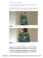
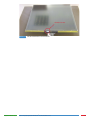
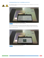
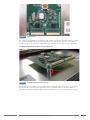
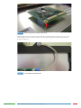
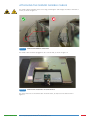
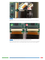
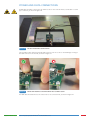
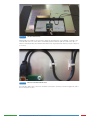
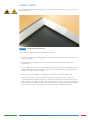
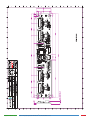
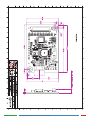
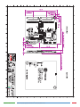
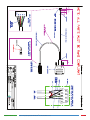
Leaders in Touch Technology
ZYTRONIC
PROJECTED CAPACITIVE ZXY100/110®
TOUCH CONTROLLER & SENSOR
INTEGRATION MANUAL – ISSUE 1
ZYTRONIC PROJECTED CAPACITIVE ZXY100/110®
TOUCH CONTROLLER & SENSOR
INTEGRATION MANUAL – ISSUE 1
CHAPTER
Integration Manual - Issue 1
TITLE
PAGES
1.0
Introduction
5
2.0
Controller Variants
3.0
Integrating the Sensor
10 - 12
4.0
Integrating the Controller PCB
14 - 16
5.0
Attaching the Sensor Flexible Cables
18 - 20
6.0
Power and Data Connections
22 - 25
7.0
Using a Bezel
27
8.0
Integration Checks
29
9.0
Controller PCB Drawings
7-8
31 - 36
10.0
Serial Cable Drawing
40
11.0
Further Information
42
Zytronic Projected Capacitive ZXY100/110® Touch Controller & Sensor
2
USER MANUAL ISSUE RECORD
ISSUE NUMBER
Issue 1
RELEASE DATE
13th June 2013
COMMENTS
First Release
EXPLANATION OF SYMBOLS USED WITHIN
THIS MANUAL
Warning Hazardous Voltage.
Caution - item is susceptible to electrostatic discharge (ESD) damage
if proper precautions are not taken.
Integration Manual - Issue 1
Zytronic Projected Capacitive ZXY100/110® Touch Controller & Sensor
3
INTRODUCTION
1
INTRODUCTION
SHIPPING DAMAGE
On receipt of your Zytronic Projected Capacitive ZXY100/110® Touch Controller Touchscreen Product, if
you notice damage to the shipping carton, or concealed damage, be sure to save all packing materials
for later inspection by the carrier, who is responsible for any shipping damage.
WARRANTY
If failure occurs during the warranty period of the product, please contact the point of sale from which
the product was purchased.
CARE AND CLEANING
Handle the touchscreen with care prior to and during installation. Do not pull or stress cables/flexible
cables and ensure no damage is caused to the touchscreen prior to installation. Clean the touchscreen
surfaces with a glass cleaning solution and soft lint-free cloth. Ensure that the surfaces are clean and
dry before integration of the touchscreen.
Industry standard Anti-static procedures for electronic equipment must be followed when handling the
touchscreen sensor and controller PCB during all stages of unpacking and installation of the product to
prevent damage to the product due to high levels of ESD.
UNPACKING YOUR TOUCHSCREEN
Ensure that the following items are present and in good condition:
Zytronic Projected Capacitive ZXY100/110® Touch Controller(s) and touchscreen sensor(s).
Users can download the latest Zytronic Projected Capacitive ZXY100/110® Touch Controller Touchscreen
Driver / Configuration Software and User Manual directly from the Zytronic website.
www.zytronic.co.uk/support
BEFORE YOU BEGIN
Before proceeding with the touchscreen installation ensure the following:
99 Your Windows operating system is correctly installed and operating with your mouse.
99 Ensure that all other touchscreen manufactures Driver Software/old touchscreen Driver software is
uninstalled from the host computer to avoid software conflicts.
99 Ensure that there is a free USB or Serial port available on the host computer to connect the desired
Zytronic Projected Capacitive ZXY100/110® Touch Controller Touchscreen.
99 Ensure that Industry standard Anti-static procedures for electronic equipment are followed during
unpacking and installation of the product.
Integration Manual - Issue 1
Zytronic Projected Capacitive ZXY100/110® Touch Controller & Sensor
5
CONTROLLER VARIANTS
2
CONTROLLER VARIANTS
The Zytronic Projected Capacitive ZXY100/110® PCT Self Capacitive Touch Controller range consists
of 5 distinct variants: 3x ZXY100® controllers with either USB or Serial connectivity; and 2x ZXY110®
controllers with USB only connectivity. See Table below.
Both ZXY100® and ZXY110® controllers will work in either single or dual touch mode (depending on the
Operating System used). The ZXY110® controller provides additional electromagnetic compatibility (EMC)
noise immunity for applications where surrounding electromagnetic interference (EMI) is a problem.
FIGURE 1
32 INPUT ZXY100/110® USB CONTROLLER FOR SMALL SENSOR SIZES
FIGURE 2
64 INPUT ZXY100/110® USB CONTROLLER FOR MEDIUM SENSOR SIZES
ZXY100® CONTROLLER
SENSOR SIZE
Integration Manual - Issue 1
USB
SERIAL
ZXY110® CONTROLLER
USB
5 - 18”
ZXY100-U-OFF-32
ZXY100-S-OFF-32
ZXY110-U-OFF-32
19 - 47”
ZXY100-U-OFF-64
ZXY100-S-OFF-64
ZXY110-U-OFF-64
48”+
ZXY100-U-OFF-128
ZXY100-S-OFF-128
n/a
Zytronic Projected Capacitive ZXY100/110® Touch Controller & Sensor
7
FIGURE 3
128 INPUT ZXY100® USB CONTROLLER FOR LARGE SENSOR SIZES
For USB versions, a USB cable with mini-B plug is required. Serial versions require a Serial cable with a
Molex type connector, as specified in the Serial Cable drawing in section 10.0.
FIGURE 4
Integration Manual - Issue 1
MOLEX CONNECTOR USED ON SERIAL CONTROLLERS
Zytronic Projected Capacitive ZXY100/110® Touch Controller & Sensor
8
INTEGRATING THE SENSOR
3
INTEGRATING THE SENSOR
To integrate the sensor, you will require a suitably sized LCD with a display area close to the active area
of the sensor, as shown in Figure 5 (the active area of the sensor can be found on the corresponding
Zytronic sensor drawing). Where possible, it is advisable to have the active area of the sensor 2-3 mm
oversized on all four edges in relation to the LCD display area. This will allow for some misalignment
during integration.
FIGURE 5
SUITABLE LCD TO MOUNT THE SENSOR TO
Foam gasket should be used around the perimeter of the LCD to provide an air gap between the LCD
face and the rear of the sensor, as shown in Figure 6. This air gap is necessary to prevent excessive
electrical noise from the LCD causing interference to the sensor.
Guidelines for the required thickness of the gasket can be seen in the table below and are sufficient for
most LCDs. Some LCDs with very high levels of noise may require greater spacing which would need to
be determined by testing.
Integration Manual - Issue 1
SENSOR SIZE
GASKET THICKNESS
5 - 22”
3mm
22 - 32”
4mm
32 - 46”
6mm
46 - 65”
8mm
65 - 84”
10mm
Zytronic Projected Capacitive ZXY100/110® Touch Controller & Sensor
10
FOAM GASKET
FIGURE 6
FOAM GASKET APPLIED TO LCD TO PROVIDE AIR GAP BETWEEN LCD AND SENSOR
If the sensor is only to be fitted to the LCD temporarily and kept horizontal, a single sided, electrically
non-conductive, low performance gasket can be used, such as EPDM (Ethylene Propylene Diene
Monomer) foam sealing strip, as shown in Figure 7. For permanent applications, or where the weight
of the sensor is to be held only by the gasket, a higher performance gasket such as 3M VHB tape can
be used. This will normally require the gasket to be built up to the correct thickness with several layers.
Different VHB tapes are available depending on the material of the surfaces it is adhering to. Any
gasket used must be non-sulphurous and maintain its adhesion at any temperature that it may be
subjected to in service.
FIGURE 7
GASKET APPLIED TO THE LCD PERIMETER
The sensor should be positioned on the LCD with the sensor active area (as defined on the Zytronic
product drawing) centred on the LCD display area. The glass face (with ‘Viewing Face’ label) should be
visible, as shown in Figure 8. The sensor can be positioned as shown or rotated by 180 degrees (so that
the flexible cables are on the top edge). The position should be chosen which gives the best clearance
for mounting the controller PCB on the rear of the LCD.
Sensor designs are also available with the flexible cables in alternative positions. If required, the sensor
can be cleaned on the front (glass) face and rear (polyester) face with a glass cleaning solution and a
soft lint-free cloth.
Integration Manual - Issue 1
Zytronic Projected Capacitive ZXY100/110® Touch Controller & Sensor
11
VIEWING FACE LABEL
FIGURE 8
Integration Manual - Issue 1
SENSOR MOUNTED ONTO LCD WITH GASKET
Zytronic Projected Capacitive ZXY100/110® Touch Controller & Sensor
12
INTEGRATING THE
CONTROLLER PCB
4
INTEGRATING THE CONTROLLER PCB
The components on the rear of the LCD should be arranged to allow a suitable space for the controller
PCB, as shown in Figure 9.
FIGURE 9
REAR OF LCD READY FOR CONTROLLER MOUNTING
The controller PCB should be positioned so that the flexible cable(s) can reach their respective ZIF
socket(s) without crossing over other cables or PCBs. There should also be sufficient space around the
USB socket to attach the cable. Ideally avoid placing the controller within ~30mm of other PCBs and
cables, as shown in Figure 10.
FIGURE 10
Integration Manual - Issue 1
CONTROLLER POSITION ON REAR OF LCD
Zytronic Projected Capacitive ZXY100/110® Touch Controller & Sensor
14
FIGURE 11
CONTROLLER PCB
The controller should ideally be mounted to metal standoffs pre-fitted to the metal chassis so that there
is a good low impedance ground connection between the controller PCB and LCD metal chassis, as
shown in Figure 12. The controller PCB should be spaced at least 5mm away from the metal chassis.
CONTROLLER SPACED 5MM ABOVE METAL WORK AND GROUNDED
MINIMUM 5MM GAP
FIGURE 12
TO METAL CHASSIS VIA METAL STANDOFFS
If mounting via metal standoffs is not possible, double sided gasket pads can be used. The controller
PCB should still be spaced at least 5mm away from the mounting surface, as shown in Figure 13.
Any gasket used must maintain its adhesion at any temperature that it may be subjected to in service.
Integration Manual - Issue 1
Zytronic Projected Capacitive ZXY100/110® Touch Controller & Sensor
15
MINIMUM 5MM GAP
FIGURE 13
DOUBLE SIDED GASKET PADS MOUNTING OPTION
If gasket pads are used to mount the controller PCB, a separate ground connection from one of the
controller PCB screw holes must be made to the LCD chassis using a low impedance ground cable,
as shown in Figure 14.
FIGURE 14
Integration Manual - Issue 1
LOW IMPEDANCE GROUNDING CABLE
Zytronic Projected Capacitive ZXY100/110® Touch Controller & Sensor
16
ATTACHING THE SENSOR
FLEXIBLE CABLES
5
ATTACHING THE SENSOR FLEXIBLE CABLES
The flexible cable bend radius at the sensor edge, and along the cable length, should be a minimum of
2.5mm, as shown in Figure 15.
MINIMUM 2.5MM RADIUS
FIGURE 15
FLEXIBLE CABLE BENDING AT SENSOR EDGE
The flexible cables should be plugged into the controller PCB, as shown in Figure 16.
FIGURE 16
FLEXIBLE CABLES PLUGGED INTO THE CONTROLLER PCB
The gold contact side of the flexible cable should be visible, as depicted on the label shown in
Figure 17.
Integration Manual - Issue 1
Zytronic Projected Capacitive ZXY100/110® Touch Controller & Sensor
18
FIGURE 17
LABEL SHOWING STANDARD FLEXIBLE CABLE INSERTION ORIENTATION
Care should be taken to ensure the flexible cables are fully inserted into the ZIF sockets, as shown in
Figure 18.
FIGURE 18
CORRECT AND INCORRECT FLEXIBLE CABLE INSERTION INTO ZIF SOCKET
Once the flexible cables have been correctly inserted into the ZIF sockets, the ZIF connector locking bars
must be pressed down in order to lock the flexible cables into the ZIF sockets, as shown in Figure 19.
Integration Manual - Issue 1
Zytronic Projected Capacitive ZXY100/110® Touch Controller & Sensor
19
FIGURE 19
Integration Manual - Issue 1
ZIF CONNECTOR LOCKING BAR IN UNLOCKED AND LOCKED POSITIONS
Zytronic Projected Capacitive ZXY100/110® Touch Controller & Sensor
20
POWER AND DATA
CONNECTIONS
6
POWER AND DATA CONNECTIONS
A USB cable should be connected to the mini-B socket on the controller PCB (or Serial cable for Serial
type controllers), as shown in Figure 20.
FIGURE 20
USB CABLE PLUGGED INTO CONTROLLER PCB
Care should be taken when inserting the USB connector into the socket to avoid damage or lifting of
the USB connector from the PCB, as shown in Figure 21.
FIGURE 21
CORRECT AND INCORRECT USB CABLE INSERTION INTO USB MINI-B SOCKET
The USB cable should be fixed to the chassis near to the controller PCB, as shown in Figure 22.
Integration Manual - Issue 1
Zytronic Projected Capacitive ZXY100/110® Touch Controller & Sensor
22
FIGURE 22
USB CABLE HELD IN PLACE
Adding cable clips similar to those shown in Figure 23 will reduce the risk of damage occurring to the
controller PCB connector if the cable is accidentally pulled. If adhesive pads are used on the clips, it
must be ensured that they will maintain their adhesion at any temperature that they may be subjected
to in service.
FIGURE 23
CABLE CLIPS HOLDING CABLE IN PLACE
The LCD video and power connections should be connected to the LCD, as shown in Figure 24, and to
the PC and power sockets.
Integration Manual - Issue 1
Zytronic Projected Capacitive ZXY100/110® Touch Controller & Sensor
23
FIGURE 24
VIDEO AND POWER CONNECTIONS CONNECTED TO LCD
The completed integration is shown in Figure 25.
FIGURE 25
COMPLETED INTEGRATION
The USB cable from the controller should be connected to an available USB 1 / USB 2.0 compatible port
on the computer, as shown in Figure 26. The USB cable should be a maximum length of 5 metres, and
plug directly into a USB port on the PC.
Integration Manual - Issue 1
Zytronic Projected Capacitive ZXY100/110® Touch Controller & Sensor
24
FIGURE 26
Integration Manual - Issue 1
CONNECTING THE USB CABLE TO THE HOST PC
Zytronic Projected Capacitive ZXY100/110® Touch Controller & Sensor
25
USING A BEZEL
7
USING A BEZEL
The integration design may include a plastic or metal bezel to be used over the front of the sensor, as
shown in Figure 27.
FIGURE 27
SENSOR WITH METAL BEZEL FITTED
If this is the case, the following points should be considered:
99 If the bezel is metal, a 3mm spacing gasket is recommended between the front of the sensor and
the rear of the bezel.
99 A metal bezel must be grounded to a common ground point with the metal chassis and
controller PCB.
99 For good edge performance, it is recommended that the bezel is set back from the LCD viewing
area by a minimum of 5mm. For edge flick gestures as found in Windows 8, increasing the bezel
aperture size further may be beneficial.
99 In most cases, the spacing gasket used will also be required to provide a watertight seal.
99 For environments where the sensor surface may be subjected to rain or water droplets, it is
recommended that a metal bezel has a not conductive intermediate section between the sensor
surface and the inner edge of the bezel. This should be angled such as to prevent any ledge where
water can collect. The purpose of this is to prevent water from forming a continuous ground path
from the sensor surface to the metal bezel, as this could result in undesirable behaviour.
Integration Manual - Issue 1
Zytronic Projected Capacitive ZXY100/110® Touch Controller & Sensor
27
INTEGRATION CHECKS
8
INTEGRATION CHECKS
Once you have correctly completed a standard integration, you should be able to answer ‘Yes’ to the
following questions:
99 Is the gasket used between the LCD and the touch sensor of the correct thickness?
99 Is the sensor fitted with the glass face forward (Viewing Face Label visible)?
99 Is the controller grounded either through the mounting standoffs or via a low impedance
ground cable?
99 Is the controller spaced away from the metal chassis by at least 5mm?
99 Are the flexible cables bent to radius of no less than 2.5mm where they attach to the glass and
anywhere else along their length?
99 Are the flexible cables inserted into the correct ZIF connector sockets?
99 Are the flexible cables inserted into the ZIF connector sockets with the gold contacts visible?
99 Are the flexible cables fully inserted into the ZIF connector sockets?
99 Are the flexible cables locked into the ZIF connector sockets?
99 Is the USB cable plugged directly into a USB port on the PC?
99 If a metal bezel has been used, is it spaced away from the front face of the sensor with the correct
gasket thickness of 3mm?
99 If a metal bezel has been used, is it grounded to a common ground point with the metal chassis
and controller PCB?
Integration Manual - Issue 1
Zytronic Projected Capacitive ZXY100/110® Touch Controller & Sensor
29
CONTROLLER PCB DRAWINGS
9
Integration Manual - Issue 1
Zytronic Projected Capacitive ZXY100/110® Touch Controller & Sensor
31
Integration Manual - Issue 1
Zytronic Projected Capacitive ZXY100/110® Touch Controller & Sensor
32
Integration Manual - Issue 1
Zytronic Projected Capacitive ZXY100/110® Touch Controller & Sensor
33
Integration Manual - Issue 1
Zytronic Projected Capacitive ZXY100/110® Touch Controller & Sensor
34
Integration Manual - Issue 1
Zytronic Projected Capacitive ZXY100/110® Touch Controller & Sensor
35
Integration Manual - Issue 1
Zytronic Projected Capacitive ZXY100/110® Touch Controller & Sensor
36
Integration Manual - Issue 1
Zytronic Projected Capacitive ZXY100/110® Touch Controller & Sensor
37
Integration Manual - Issue 1
Zytronic Projected Capacitive ZXY100/110® Touch Controller & Sensor
38
SERIAL CABLE DRAWING
10
Integration Manual - Issue 1
Zytronic Projected Capacitive ZXY100/110® Touch Controller & Sensor
40
FURTHER INFORMATION
11
FURTHER INFORMATION
Further information and technical support can be obtained by contacting Zytronic:
Zytronic Displays Ltd
Whiteley Road
Blaydon on Tyne
Tyne & Wear
NE21 5NJ
UK
Tel: +44 (0) 191 414 5511
Fax: +44 (0) 191 414 0545
Email: [email protected]
Website: www.zytronic.co.uk
Company No. 379908
Registered in England
WHAT WE DO
Manufacturing touch technology products from a single site comprising three modern factory
premises in Blaydon upon Tyne, United Kingdom, Zytronic produce a range of projected capacitive
technology (PCT™) touch interactive products which are used in electronic displays for information
kiosks, ATM’s, ticketing and gaming machines, as well as by military, computer, telecommunications
and medical manufacturers.
Our diverse range of touch sensor technology products are all based on our internationally award
winning projected capacitive technology, providing a highly durable and stable range of touch products
where the sensing element is uniquely embedded behind the first surface of the touch substrate.
The Zytronic in-house glass processing facilities include automated cutting, edge grinding, polishing
and drilling equipment complemented by bending and thermal tempering ovens and silk-screen
printing equipment. These facilities are complemented by the lamination, material science and
electronics skills and expertise of our dedicated staff.
Zytronic also has in-house electro-plating and coating facilities which enable the production of optical
filters to enhance the performance of information displays and provide anti-vandal protection, RFI/EMI
filters to minimise electromagnetic emissions and interference from electronic displays and specialised
laminated products for the defence, rail, road and automotive industries.
Our commitment to innovative touch technology development in composite technology, stringent
(ISO approved) quality controls and fast-response customer service is complimented by our own
dedicated external sales team, undertaking both direct sales to major customers and assisting with
sales through the extensive world-wide network of agents and distributors.
Zytronic - the Touch Technology specialists - providing a range of projected capacitance
technology touch interactive products.
Our award winning projected capacitive touch technology products are being used in a range of
industrial and public access and service applications such as information and financial kiosks, digital
signage, ticketing, gaming and vending machines, as well as telematics and medical devices.
Integration Manual - Issue 1
Zytronic Projected Capacitive ZXY100/110® Touch Controller & Sensor
42