Download EC Technology compendium 2011

Transcript
GreenTech
EC technology
Hardware and software.
Technology and application.
Commutate electronically, benefit economically
The engineer’s choice
Symbols that define standards
Green through and through
In order to underline our philosophy, efforts and achievements when it
GreenTech
follows a firm
philosophy.
comes to environmental protection, we have put them all in a nutshell with
GreenTech. The benefits of GreenTech mesh with one another from the
GreenTech is
pro-active
development.
GreenTech
pays off
for our
customers.
initial development of our products through to their use – and they form a
circuit that finishes right where it began: with the philosophy that we shall
soon build another, even more eco-friendly and economical product.
Philosophy:
GreenTech is
eco-friendly
production.
GreenTech is
acknowledged
and certified.
Each new development must exceed the economic and ecological performance of its predecessor.
Development:
Materials, products and processes are selected and designed in an environmentally responsible manner using state-of-the-art methods.
Production:
State-of-the-art energy, air-conditioning and ventilation technology provides maximum energy efficiency in our plant.
Awards:
Environmental prizes, distinctions and energy efficiency that beats even
the most stringent limits speak for themselves.
Application:
Our high-efficiency products use GreenTech EC technology and boast
enormous energy savings with top performance.
For fans with an input capacity of greater than 125 W, the new European
Energy-related Products Directive (ErP) to improve energy efficiency will
enter into force in 2015 at the latest. Thanks to groundbreaking GreenTech
EC technology, all of our ebm-papst fans and motors in these performance
classes exceed the ErP Directive even today.
2
Contents
As your R&D partners, the economic success of your products is just as important to us at it is to you. Our development of fans,
blowers and drive solutions, which are used in a wide variety of industries and applications, is always focused on maximum
efficiency. Cost efficiency is the goal, and energy efficiency is one of the most direct ways there! Taking that path also means
assuming environmental responsibility. In this brochure, we will show what ebm-papst GreenTech EC technology can do for
economy plus ecology – and hence for us all!
Claim
4 | 5
Efficiency
6 | 7
Intelligence
8 | 9
Comfort
10 | 11
A holistic approach
12 | 13
Communication
14 | 17
Software
18 | 19
Control
20 | 21
Smartphones
22 | 23
Bluetooth ®
24 | 25
USB adapter
26 | 27
Ethernet
28 | 29
EC Controller
30 | 31
Pressure control
32 | 33
Pressure sensors
34 | 35
Temperature sensors/temperature modules
36 | 39
3
GreenTech EC technology:
the original.
Not all EC technology is the same. As a matter of fact, many different drive types are categorised under this generic term today,
such as PM (permanent magnet motors), ECM (electronically commutated motors) and BLDC (brushless DC motors). ebm-papst
was one of the first manufacturers to recognise the economic as well as environmental advantages of EC technology and
significantly advanced its development. As early as 1965, we were on the market with the world’s first EC compact fan – 30 years
before any other manufacturer. For this reason, GreenTech EC technology made by ebm-papst is the outstanding product of a
consistent efficiency strategy – in a manner of speaking, the original among the EC technologies.
The pioneer in EC technology: ebm-papst
Continuously saving motors
Developing and advancing EC technology has certainly been one of our
The decisive advantage of fans and motors with GreenTech EC technology
most important challenges. The success we have had can be seen today
compared to conventional asynchronous motors lies in their significantly
in the world’s largest range of EC fans and motors. For over 13 years,
higher efficiency of up to 90 % as opposed to 20–70 % with AC motors.
mains-powered GreenTech EC technology has been the worldwide standard
This means not only better use of primary energy, but also less lost heat
in areas such as clean room technology, providing reliable performance
and hence a longer service life.
24 hours a day, 365 days a year.
The efficiency advantage is ever clearer in partial-load operation, since the
With its outstanding position both environmentally and economically,
built-in electronics make the EC motors continuously adjustable. This
GreenTech EC technology offers comprehensive advantages to beginners
means the speed can always adapted to the specific requirements. This is
as well as those switching from AC to EC. The topic of sustainability has
an advantage which leads to entirely new opportunities for savings in
long since become a criterion crucial to making a purchase decision – for
many applications, but also provides more comfort – for example by the
our customers just as for their end customers. There is no question that
significantly reduced noise level.
we will continue developing and perfecting GreenTech EC technology in
the future, in order to meet the future requirements of our customers, the
market and society – but above all also our own convictions.
4
Tremendous energy savings
of 30 % on average
Future-proof and ready
for ErP2015
Hardware and software
from a single source
Can be used worldwide
(due to wide voltage input)
Intelligent electronics for
numerous control functions
Easy 1:1 replacement from AC technology to GreenTech EC technology
Over 40 years of experience
in the area of EC technology
GreenTech as implemented
purchase proposition
GreenTech EC – the technology that combines the best technologies
Moreover, GreenTech EC motors and fans can be used everywhere: They
Viewed technically, GreenTech EC technology can be labelled as “soft
can be operated in a direct current (DC) as well as an alternating current
commutation”. This involves a combination of commutation strategy and
(AC) mains (1 and 3 phases). The size is no longer an impediment, either.
motor design. The result for the customer is low-noise operation without
By having the electronics fully integrated into the motor, many of our EC
structure-borne noise. This means that we use permanent magnet motors
fans already have exactly the same dimensions as their AC counterparts.
in a variety of designs to achieve the best performance for the respective
application and the desired power range. The intelligent electronics balance
So there is no more reason to rely on conventional AC fans. This applies
out synchronisation tolerances, ensuring that all that comes out in the end
to more than the development of new applications. The switch from AC
are the advantages for our customers.
to EC pays off in view of the tremendous efficiency advantages and could
not be easier, thanks to plug and play.
5
An average energy savings of 30 %:
That is a deal!
In ventilation, air-conditioning and refrigeration technology, the world of information technology, heating or building systems.
In industrial automation, automotive, or telecommunication. Wherever motors are used for drives or ventilation, energy has
to be used as sparingly as possible. Not only the consumer requires this, but also the law with its new directives for limiting
energy consumption and protecting the climate. GreenTech EC technology sets a good example: Even today, all of our EC fans
exceed the ErP Directive for 2015. And those aren’t just words – it’s a fact!
Example: Energy savings in HVAC technology
Another fact: Even for changing speeds, the GreenTech EC fan retains its
very high efficiency. With AC motors, on the other hand, the already lower
efficiency drops significantly. Thus energy savings of over 10 % are attained for condensers/evaporators in which our EC fans work, even at
nominal speed. In the continuously controlled range, the relative and absolute savings are substantially greater. Compared to GreenTech EC tech-
29%
Savings
6 fans work in one heat exchanger.
At an average duty cycle of 75% this
means an annual savings potential
of over 24 MWh. This corresponds
to approx. 14.4 tonnes of CO2 and
saves 2,814 euro*.
e. g. A3G800 axial fan
nology, conventional phase-angle control can use twice as much energy,
if not more, depending on the operating point.
[W]
[W]
A small supermarket operates 40
67%
1 800
1 600
AC with phase-angle control
AC with transformer
AC with frequency inverter
ebm-papst EC
1 400
Savings
1 200
fans in the refrigeration counters.
The lower intrinsic heating of the
energy-saving motor allows a 30 %
shorter working time. Over a year,
that means a savings potential of
more than 9.4 MWh and 5.6 tonnes
+650 W
+118 %
of CO2. Cost saving: 1,080 euro*.
+200 W
+36 %
6 precision air conditioning units
e. g. W1G200 axial fan
1 000
800
600
550 W
400
Pe
Pe
200
qV
7 000
Pe = Input power
9 000
11 000
13 000
15 000
17 000
[m3/h]
Savings
computer centre, each equipped
with 3 EC fans. With a duty cycle of
100 %, up to 50 MWh of electricity
can be saved. That corresponds
to about 30 tonnes of CO2 and
e. g. R3G500 centrifugal fan
5,898 euro* every year.
q V = Air flow
Power input for various control methods
Using this formula, you can easily calculate the cost savings
for your application.
Cs = Rt • Es • Ec
Cs = Cost savings (euro/year)
Rt = Run-time (hours/year)
Es = Energy savings (kW)
Ec = Energy costs (euro/kWh)
6
22%
are working in the IT rooms of a
* With CO2 emissions of 600 kg/MWh (German energy mix) and 11.69 euro cent/kWh, average electricity price for
industry in Germany (status: January 2010, source: VEA, BDEW).
Best performance under all conditions:
That is guaranteed!
Just one example for demand-oriented use of fans: the air-conditioning and refrigeration systems of a supermarket. Here one
needs full speed and output in the summer at peak load, reduced output in the winter months and whisper-quiet operation at
low speeds overnight. These are just examples, but they also reflect real-world conditions that GreenTech EC technology from
ebm-papst takes fully into account. With its intelligent open and closed-loop control options, the air-conditioning or cooling
systems can be adapted easily to all requirements of manufacturers, owner/operators, consumers, and the general public.
With guaranteed high savings potential for energy and costs.
Example: Possible power for condensers/evaporators
The graphic below, based on the example of size 800 ebm-papst axial fans,
makes the difference between AC and GreenTech EC technology clear: Our
EC technology can be used in the entire blue range. Moreover, in the dark
blue range it has significant power reserves compared to AC technology.
GreenTech EC technology allows operation at peak load – with very quiet
[Pa]
operation.
Limit EC
250
Limit AC
200
150
100
Δ Psf
50
qV
Psf = Pressure increase
5 000
10 000
15 000
20 000
25 000
[m3/h]
q V = Air flow
Power range of AC and EC fans
AC
EC
EC power reserves
7
Simply turn down the costs:
That’s intelligent!
Here is an example of intelligent energy savings from real-world applications: A condenser, as used for example in cooling
equipment, is equipped with 4 AC fans and alternatively with ebm-papst GreenTech EC technology. The energy savings
possibilities of the GreenTech solution compared to AC fans are considerable – as the graphics below show.
Example: Expect considerable savings potential
This is a comparison of two condensers, each with four size 800 axial fans:
one condenser with conventional AC technology, the other with the innovative GreenTech EC technology. To configure the respective optimal cooling
capacity for different cooling requirements, the air performance is adapted
to the fans.
For the condenser with AC fans, this is frequently done by cutting individual fans in and out by means of external switchgear. The fans that remain
in operation continue to run at full speed.
The condenser with GreenTech EC fans has a better solution: it does this by
continuously adjusting the speed. All fans remain in operation – resulting
in substantial energy savings in power input.
The graphics below show the possible energy savings and noise reduction
in direct comparison of on/off operation and continuous speed adjustment:
100 %
dB(A)
Power consumption of AC motors
Power consumption of EC fans
Savings from continuous speed adjustment
Benefit of continuous
speed adjustment
–3
–6
75 %
–9
Benefit of continuous
speed adjustment
–12
50 %
–15
–18
25 %
Sound pressure level of AC motors
Sound pressure level of EC fans
Noise reduction from continuous
speed adjustment
Pe
LpA
–21
qV
25 %
Pe = Input power
50 %
75 %
100 %
qV = Air flow
Low energy consumption: The bars show the power input of fans that are
activated incrementally as needed. The air performance is reduced by 50 %
if two fans are shut off. The blue line shows the power input with continuous
speed adjustment.
8
qV
25 %
LpA = Sound pressure level
50 %
75 %
100 %
qV = Air flow
Lower noise: While shutting off half of the fans (one-half of the air flow)
decreases the noise level by only about 3 dB, speed reduction to one-half
the air flow attains an improvement of 15 dB.
Our example in numbers: direct comparison between four conventional AC fans in on/off operation and four continuously speed-controlled GreenTech
EC fans. The table below shows only the advantage of the power input. By means of the constant higher efficiencies of our GreenTech EC motors,
the real energy savings are significantly higher yet again.
On/off operation: To adapt the air performance to
various cooling requirements, the current practice
is still to switch individual AC fans on or off.
Modulating operation: All devices and fans
remain in operation simultaneously. The optimum cooling capacity is attained via continuous
closed loop speed control of all fans.
The direct comparison: With closed loop speed
On/off operation for AC fans
AC
Air performance
Number of fans in operation
speed
Power input in kW
100 %
75 %
50 %
25 %
4
3
2
1
100 %
100 %
100 %
100 %
7.40
5.55
3.70
1.85
Modulated operation: closed-loop speed control of GreenTech EC fans
EC
Air performance
Number of fans in operation
speed
Power input in kW
100 %
75 %
50 %
25 %
4
4
4
4
100 %
75 %
50 %
25 %
6.68
2.84
0.84
0.11
Air performance
Reduction of power input
control, the power input is decreased substantially: with demand-oriented adaptation to onequarter of the rated output, even up to 94 %.
with EC
100 %
75 %
50 %
25 %
10 %
49 %
77 %
94 %
Example calculation:
Savings potential in kWh: If we assume the
Load duty cycle
load profile shown to the right, energy demand is
decreased substantially in modulating operation.
The annual energy demand is reduced by 56 %!
Annual hours
AC: power requirement with
EC: power requirement with mod-
per load case
on/off operation kWh per year
ulating operation kWh per year
876
2,628
3,504
1,752
6,482
14,585
12,965
3,241
5,852
7,464
2,943
193
8,760
37,274
16,451
10 % at 100 %
30 % at 75 %
40 % at 50 %
20 % at 25 %
At this load profile, the annual energy consumption is reduced by: 56 %
Savings potential in EUR: The use of innovative
Savings from EC
Savings from EC
Savings from EC
Savings from EC
GreenTech EC technology always pays off for the
per year (0.09 €/kWh)
per year (0.12 €/kWh)
per year (0.15 €/kWh)
per year (0.18 €/kWh)
1,874 €
2,499 €
3,123 €
3,748 €
owner/operator.
Unprecedented: a win-win for the owner/operator and the environment!
in real money for every owner/operator, it also conserves precious energy
When you use intelligent GreenTech EC technology from ebm-papst,
resources. But that’s not all. In addition to the savings effect, you can
everybody wins: companies, people and the environment. It not only pays
also expect a significant reduction of noise emissions. At lower speeds,
off
GreenTech EC fans are even quieter. You will hardly know they are there.
9
Minimum noise emissions:
That sounds good!
Think about air-conditioning in office buildings. Think about heating boilers in residential spaces, range hoods or refrigerators,
electronics cooling of computers, ventilation and air-conditioning in the automobile, in commercial vehicles, and on and on. Of
course, in all of these applications, function, reliability and safety are everything! Still, the consumer wants to hear absolutely
nothing about it – quite literally. Here is something that sounds good: In every application, GreenTech EC fans, EC blowers and
Example: Noise reduction at all speeds
[dBA]
EC drives made by ebm-papst provide perfect power that can barely be heard!
ebm-papst GreenTech EC technology is really something to hear – or,
actually, not to hear. You hear no motor noise across the entire speed
70
range. The advantage: When demand for cooling is low, such as at night,
very
A
60
low operating speeds can be selected. The resonance levels typical for frequency inverter operation – which, by the way, are not always eliminated
50
even in our competitors’ EC products – or “phase noise” do not exist in our
products, as a different operating principle is involved.
40
B
Furthermore, combining AC motors with frequency inverter without an
AC with phase-angle control
AC with transformer
AC with frequency inverter
ebm-papst EC
30
Lp A
all-pole sinusoidal filter can cause winding and bearing damage.
qV
2 000
4 000
6 000
Lp A = Sound pressure level q V = Air flow
8 000
10 000
[m³/h]
Noise behaviour for various control methods
A: Phase-angle control, hum noise (300 Hz)
B: Frequency inverter whistle – motor and device resonance
caused by a motor with a frequency inverter
10
Everything included, from the control to motor protection:
That’s plug-and-play!
Move air – for an all-inclusive price! This is another of the great benefits of GreenTech EC technology from ebm-papst.
Whether you’re looking at the PID servo amplifier, radio interference filter, mains filter, motor protection, or current supply for
external sensors, our EC products already have all the features they will ever need. Plug and play is this easy: Just do the
application check! See for yourself which additional components are required for conventional AC products or even competitor’s
products. As you can see below, we have simply ticked all of the features already included in an GreenTech EC fan.
Example: Your all-inclusive advantage with a GreenTech EC fan
1 PID servo amplifier
2 Power Factor Controller/mains filter
3 Radio interference filter
4 Motor protection
5 Current supply for sensor
Fewer additional peripherals, less installation complexity – and all useful
features already built-in and completely inspected. That is how simple
GreenTech EC technology is to use in real-world applications.
The features in detail:
01 PID servo amplifier: For pressure or temperature regulation, only
one corresponding sensor with standard analogue output (0–10 V or
4–20 mA) is necessary. The set value, control range, control function
6 Shielded wires
not necessary
and control parameters are adjustable.
02 PFC/mains filter reduces current reverse transfers. At rated output,
the power factor is typically greater than 0.9.
7 RS485 MODBUS RTU
8 Over-temperature protection
9 Motor current limit
03 The radio interference filter reduces the emission from power-related
and broadcast interference voltages and guarantees interference
immunity in rough industrial environments.
10 Alarm relay
11 Soft start
12 Connection options
04 The motor protection prevents the motor from being overloaded in all
operating states.
05 The current supply for external sensors is fed via the fan.
06 Due to the integration of the commutation electronics in the motor,
shielded wires are not necessary.
07 The open protocol standard RS485 MODBUS RTU offers many configuration options for functions, options for customising parameters
and integration of the fan in higher-level systems.
08 The over-temperature protection prevents damage to the motor and
electronics from an overload.
09 A motor current limit provides additional safety.
10 If there ever is a fault, the built-in alarm relay immediately gives
notification.
11 A soft-start function and electronic output limit when the motor
starts guarantee that the fan starts smoothly.
12 Numerous connection options, such as for external sensors, offer a
maximum of flexibility and embedding options.
Intelligent electronics – intelligent power: A GreenTech EC fan already includes
everything it will ever need.
11
Fewer types, less logistics:
That saves even before installation!
GreenTech EC technology replaces AC technology – in the best possible way. This replacement is far superior, not only in
terms of energy efficiency, noise reduction and intelligence, but also logistics! After all, you could replace up to 8 different AC
axial fans, each with different blade angles, with just a few GreenTech EC axial fans while still providing a fully equivalent replacement. Assume the highest possible flexibility for your applications, even worldwide. Expect fewer types, easy stock-keeping,
less logistics – and, in sum, a significantly reduced financial outlay.
One instead of many: How to replace AC with GreenTech EC
If we consider optimum efficiency and an ideal selection of motor sizes
for the respective operative range, then 8 AC variant fans can definitely
be replaced by 4 GreenTech EC variants. As the graphics clearly illustrate,
4 EC variants cover the entire blue area, while AC without additional open
[Pa]
loop speed control can be used on the black curves only.
250
200
150
100
Δ Psf
50
qV
Psf = Pressure increase
5 000
10 000
15 000
20 000
25 000
[m3/h]
q V = Air flow
AC in various blade angles
EC
Can be used worldwide without any problems
ebm-papst GreenTech EC fans feature a wide voltage input. Thus their curve
remains practically unchanged over the entire voltage and frequency range.
Our fans can be used worldwide, regardless of voltage and frequency.
• 3-phase, 200–240 VAC, 50/60 Hz
• 3-phase, 380–480 VAC, 50/60 Hz
• 1-phase, 200–277 VAC, 50/60 Hz
• 1-phase, 115 VAC, 50/60 Hz
Each is controllable to the required operating point.
12
GreenTech innovations:
That has future!
From the ErP Directive for 2015 it is evident: EC technology from ebm-papst is years ahead of its time. No wonder – after all,
we were one of the first technology companies to recognise the potential of electronic commutation and continuously advance
its further development. To stop now and rest on our laurels would not live up to our claim as an innovation leader in the field
of fans and drives. Therefore we continue researching and developing. In doing so, we look not only at the motor itself, but also
consider each product as a whole, to exploit all the possibilities of increased efficiency – whether in the materials, the electronic
control or the aerodynamics. Here are only a couple examples.
We are nowhere near the end
There is no question: Our EC technology is the heart of GreenTech, around
which, in the truest sense of the word, everything revolves. And that will
remain true for a long time to come. Still, our research and development
goes on continuously – in all areas of fan and drive technology. This results in innovations that set new benchmarks time and again:
The HyBlade® and RadiCal, a revolution in materials
Excellent examples of how innovative motor technology and ventilation
technology optimally complement one another are our fans with a hybrid
material structure: HyBlade and RadiCal. The combination of metal and
plastic elements in the axial and centrifugal impellers makes them particularly lightweight and enables aerodynamically optimised design options,
which together yield a previously unachieved energy efficiency – and also
enable whisper-quiet operation.
Biomaterials are the future
Increasing efficiency and conserving resources – the holistic approach
of GreenTech already begins in the development and production of our
motors and fans. Even today we are developing materials made in part of
renewable resources, such as wood, to be able to replace a portion of the
oil-based plastics in the future. Good for the environment and for your
sales proposition.
Our plant in Hollenbach not only has many brilliant minds, but also a lot of our
GreenTech philosophy. The result: 90 % lower energy consumption during production.
A prime example of our holistic thinking – and acting!
Electronics that think and save
The option of demand-oriented controllability is one of the great strengths
of EC technology. For optimum results, however, one also has to know
how to use it optimally. Here as well, ebm-papst is showing the way: on
the one hand, with a wide range of functions already integrated into all
GreenTech EC motors and fans; on the other hand, with a wide variety of
connections and interfaces, which offer you nearly unlimited control and
network capabilities.
But that is a whole different chapter – which begins on the next page …
13
Intelligent electronics with a wide range of functions:
That’s a system!
Fan networks made up of GreenTech EC fans render their service in refrigeration and air-conditioning technology, in building
ventilation, clean rooms and many other application areas. For communication with the bus systems, the ebm-papst product range
provides various interfaces and software solutions that give you optimum support for setting up and monitoring your systems.
Measuring, open and closed-loop control, automating
MODBUS RTU – the reliable standard protocol
In addition to their outstanding energy efficiency, the intelligent functions
MODBUS RTU
for open and closed-loop control are among the chief advantages of
ebm-papst GreenTech EC technology. From simply reading out the current
Interface
RS485
Baud rate*
19,200 bit/s
Frame*
8E+1
Data exchange
in accordance to ebm-papst
MODBUS RTU parameter specification
Number of nodes**
up to 247
Devices on the BUS
all MODBUS RTU-compatible devices
Fault detection
CRC16
Software support
EC Control
Fan Control
Fan Clone
speed to configuring a sensor control, the integrated electronics of our
GreenTech EC fans offer numerous options for demand-oriented and efficient operation of systems.
Depending on the planned use, application, work environment and existing
equipment, various solutions provide reliable control with your GreenTech
EC fans. For this purpose, analogue activation options such as 0–10 V and
4–20 mA for a sensor connection and connection for set value device are
available, among other things. However, digital control options and complex
controls are also possible via a digital bus system (MODBUS RTU). Likewise, external sensors connected to our fan can also be queried remotely.
On the following pages, we provide an overview of the combination options
for our software and peripherals, such as the Bluetooth wireless standard
for configuring and operating our fans, as well as the various communication standards.
** For MODBUS specification 4,0 or higher, other values are also possible.
** For installations with more than 31 fans, RS485 repeaters may have to be used, depending on the type of fan.
GreenTech EC technology and MODBUS RTU – your advantages:
– Open communication standard recognised worldwide
(non-proprietary)
– Can be integrated into a centralised energy and data
management system
– Queries of operating states
– Connectivity with other bus systems, e.g. via BACnet, KNX,
LON Works and enOcean
– Remote query and automation in the network with other
MODBUS RTU-compatible devices (actuators and sensors)
– Use of existing function libraries
– High system and transmission reliability
More information about MODBUS RTU is available at
www.modbus.org/tech.php
14
Intelligently networked and reliably controlled:
This way you have a handle on everything.
There is hardly any application for fans in which our GreenTech EC technology with its diverse communication options cannot
demonstrate its advantages – to your benefit. Take, for example, the remote monitoring ability via Internet, SMS, e-mail,
Bluetooth etc. This makes all information, including speed, motor temperature and operating messages or alarms, available at
any time – and, if desired, even anywhere in the world.
Remote monitoring – made easy
– Running time
With state-of-the-art IT infrastructure, the monitoring of functions is carried
– Speed/rpm
out via MODBUS RTU. The information can be processed and evaluated
– Current (intermediate circuit)
using MODBUS standard software, but also software such as ebm-papst
– Voltage (intermediate circuit)
EC Control or Fan Control or software on the customer’s side.
– Power input (can be calculated from current draw and voltage)
– Emergency operation function
There are basically two options for remote monitoring: First, by ebm-papst’s
– Temperature of motor
proprietary EC Control software on a host computer with an interface
– Temperature of electronics
converter. The host computer can then be accessed with remote desktop
– Temperature of power section
software (e.g. VNC, Team Viewer). Secondly, via a laptop that accesses a
– Operation mode (control of temperature, pressure and air flow;
PLC or a control device.
actuator/controller; set value/actual value; cooling/heating)
– Operation and alarm display = alarm signal
The following parameters are available for optimum energy resource
planning, load management, preventive maintenance, control commands
Additionally, external sensors connected to the terminal strip of the fans
and for troubleshooting and reprogramming remotely:
can also be queried remotely.
Remote desktop software
EC C
Interface converter
Ethernet
Art. No. 21488-1-0174
Art. No. 21489-1-0174 (UL)
RS485 (MODBUS RTU)
ontr
ol
Laptop
www
.
Host computer
Remote
monitoring
Approved controller
Remote
monitoring
RS485 (MODBUS RTU)
RS485 (MODBUS RTU)
Master
15
Communication via MODBUS RTU:
That connects!
MODBUS RTU has become established as a worldwide standard for controlling actuators and sensors due to its open and
simple protocol. We offer a wide range of GreenTech EC fans and motors that support this interface by default. Numerous
programmable logic controllers also have a MODBUS RTU interface. This makes it very easy to solve complex automation
tasks – typical uses include shopping centres, schools, office complexes, swimming pools and stores such as a bakery or
butcher’s shop. For how to interconnect the individual components optimally, refer to the illustration below.
Communication on three levels
Finally, the “field level” is where the actual actuators work, such as the
MODBUS RTU is the ideal basis for the data transfer, in order to integrate
GreenTech EC fans and motors from ebm-papst. In addition, there are
EC technology in open and closed-loop control processes. This example
numerous sensors, which for example measure the ambient temperature
shows how the network in a large building complex could look. Here the
or the pressure in coolant lines.
network’s hierarchy is divided into three levels:
The “primary level” is the level on which all data runs together. The heart
of the monitoring is the master control system (MCS). All data is collected
system. From the stored data, the usage pattern over a prolonged time
period can also be analysed and used to project future planning for usage
of operating resources.
The “field automation level” has the control centres for the various appli-
Primary level
and analysed here – for general management tasks and for optimising the
Master control
system
e.g. BACnet
Building automation control
cations: e. g. light, window blinds, air handling units (AHU), condensers
Logic Controller). PLCs are automation devices in widespread use which
are tailored to the respective application by means of programming. Alternatively, there are control devices (application controllers) that are already
designed and programmed for the specific automation task.
The control and automation levels can be connected by widely varying bus
systems. The bus systems make the process data available to the higher-
Field automation level
etc. Each of these systems has its own control unit: a PLC (Programmable
Input/output
light
Input/output
window blinds
PLC
PLC
Light
Jalousie
level control level, e. g. a BACnet system.
Light sensor
Field level
Light 1
Motion sensor
Light 2
16
Wind sensor 1
Window
blinds 1
Wind sensor 2
Window
blinds 2
ebm-papst approved controllers:
That’s a match.
High demands are placed on the control devices for a MODBUS RTU system. For one thing, they have to fulfil their control tasks
for the respective application – and those can be very different. For another thing, they have to know all the functions used by
the connected actuators in order to use them optimally. For complex automation tasks there is no universal solution, but we
have partners who specialise in this task. With our ebm-papst approved controller program, we build the bridge between our
products and those of the automation professionals. We not only offer fans, but also enable holistic solutions.
ebm-papst approved controllers
ebm-papst approved controllers are a perfect match for our EC fans. Here
GreenTech EC technology offers a wealth of control, automation and control
we distinguish two groups: Programmable Logic Controllers (PLCs) and
options. Approved controllers fully utilise these and are available from our
control devices (Application Controllers). A PLC is freely programmable,
automation partners.
while the control device is pre-programmed and configured for certain
applications. We have specialised partners for all systems.
The advantages of ebm-papst approved con-
Database
server
SMS
e-mail
Ethernet
trollers:
– Easiest programming by accessing libraries*
– Link to the state-of-the-art IT world (iPad
FTP
apps, SMS, e-mail, FTP or hardware such as
touchpanels, smartphones)
– Built-in file server, evaluation and reporting
options using Office applications
Air handling unit
AHU 1
Condenser 1
– Built-in web server, control with web browser
is possible
– Always a customised solution
PLC
PLC
AHU 1
Condenser
* only for PLC
For detailed information on ebm-papst’s
approved controller program, visit
www.ebm-papst.com/controller
Pressure sensor
GreenTech
EC fan
Pressure sensor
GreenTech
EC fan
Temperature
sensor
GreenTech
EC fan
Temperature
sensor
GreenTech
EC fan
MODBUS-RTU
17
Software and interfaces at a glance:
These go together.
Which control software is suitable for which input device and how do their features differ?
The answer is easy to find in the clearly arranged direct comparison on this double-page spread.
The perfect match: supported interfaces and protocols
Software
Application
EC Control
Fan Control
Fan Clone
EC Controller
(page 20)
(page 22)
(page 23)
(page 30)
Service purpose
Service purpose
Manufacturing –
Stand-alone control
and stationary
and mobile operation
system monitoring
mobile operation, copy
device for refrigeration
and archive settings
and air-conditioning
technology
Hardware
Bluetooth adapter
(page 24)
USB adapter
(page 26)
Ethernet – RS485
interface converter
PC/laptop
PDA/smartphone
PDA/smartphone
•
•
•
•
•
•
•
(page 28)
RS485
MODBUS RTU
(page 30)
18
•
•
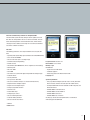
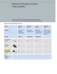
Performance features of the control software programs for PCs and PDAs
EC Control
Fan Control
EC Controller
Query and modify parameters of one fan
•
•
(•)
Modify parameters for group/entire system
•
–
–
Group view/floors
•
(•)
–
Detailed error history when software runs for long periods
•
–
–
Mapping a system layout/floor plan
•
–
–
Searching for a fan with an unknown address
•
•
•
Setting parameters graphically
–
•
–
E-mail on error
•
–
–
Support for multiple languages*
•
•
•
Support for RS485 ebmBUS
•
•
–
Support for RS485 MODBUS RTU
•
•
•
Support of Ethernet and multiple subnets
•
–
–
Duty cycle display on fan symbol
•
–
–
Display of information below fan symbol
•
–
–
Illustration of the system in a tree structure
•
–
–
Support of multiple configurations in one installation
•
–
–
German and English user manual (PDF)
•
•
•
Timer
•
–
–
Integrated help system (English)
•
–
–
Key:
• = Performance feature present
(•) = Possible in part/to a limited extent
– = Not present
* The supported languages differ for each product
19
EC Control – our high-performance control program:
This way you have a handle on everything!
The ebm-papst EC Control program enables detailed control and monitoring of fan groups in ebmBUS and MODBUS RTU networks. The multilingual and intuitively operated interface in the familiar Windows® system environment provides you with easy
and logical control. For example, you can position fans on the floor plan of your building in a simple and clearly arranged manner.
This lets you always keep tabs on your networks, even if they have many thousands of fans. In version 2.0 you can also expect
numerous innovations such as additional languages, expanded help functions, a configuration wizard and a redesigned fan
configuration dialogue with extensive self-explanatory categories. This way the system as well as the Ethernet/RS485 interface
converter and the fan parameters can be configured easily and conveniently.
EC Control software for EC systems
EC Control enables visualisation and programming of ebmBUS and MODBUS
RTU fan networks and can be configured for USB, serial and Ethernet interface converters. Since Version 2.0, EC Control also supports the Bluetooth
adapter. For shorter latencies, multiple interface converters can be connected.
The software supports the maximum number of devices allowed by the
respective bus system (up to 7,905 fans for ebmBUS and 247 for MODBUS
RTU). However, these can be expanded by additional subnet addressing.
This makes it possible to use each fan address not just once per system,
but also once per interface converter. Thus up to 4 x 247 fans are now
supported when using the MODBUS RTU protocol and 4 x 7,905 fans are
supported when using the ebmBUS protocol.
Where necessary, the variable user interface of EC Control makes it easy
Functions
to distinguish between the various interface converters. It shows only the
– Configuring over 40 fan parameters such as operating mode, set value
entries that are relevant to the specific system. Additional features include
and control parameters
support of a second monitor, a tree-shaped management structure for
– Changing fan addresses
finding individual fans in large systems efficiently and an online help.
– Reading out fan parameters such as actual speed, serial number and
production date
– Reading out fault status and fault memory
– Saving various configurations as an exportable and editable profile
– Monitoring installations, including the possibility of reporting failures by
e-mail
– Administration of multiple systems within one program installation
– Support of RS232/RS485 and Ethernet/RS485 interface converters as
well as USB and Bluetooth
– Simultaneous monitoring of ebmBUS and MODBUS RTU-based installation components (requires several interface converters)
– Output of status messages via the USB relay box (Art. No. 10450-1-
USB relay box (Art. No. 10450-1-0174) for
processing various status messages of fans.
0174) with the option of triggering an external action, e. g. signal lamps
– Monitoring of up to 4 x 247 fans with MODBUS RTU systems and
4 x 7,905 fans with ebmBUS systems
– Expanded export and import of systems in CSV format with all relevant
data – also for exchanging data between operating systems with different language versions
20
System version: EC Control 2.0
System requirements:
Item number: 25714-2-0199
– Windows XP Service Pack 3 or Windows 7
Delivery scope:
– Approx. 60 MB of available hard drive space; when using the
CD-ROM with
– Software in DE, EN, ES, FR, IT, NL, FN, JP, CHS (simplified),
CHS (traditional), RU
– Application manual and operating instructions in DE and EN
in PDF format on CD
– Quick video guides
USB relay box, additional memory is required for its drivers
– Monitor with a resolution of at least 1024 x 768 pixels and
16-bit colour depth
– CD-ROM drive (only needed during installation)
– At least one interface converter of the following types:
• Bluetooth adapter (Art. No. 21501-1-0174)
• USB (Art. No. 21490-1-0174)
• Ethernet (Art. No. 21488-1-0174/21489-1-0174 (UL))
• RS 232 (Art. No. 21487-1-0174 and 21495-2-0174)
21
Control software for smartphones:
The best solution when on the move.
For wireless programming and monitoring, ebm-papst fans equipped with an RS485 interface can
communicate with smartphones/PDAs via the ebm-papst Bluetooth adapter. Diagnostics in the event
of fault are likewise possible. To do so, the Bluetooth adapter creates a bi-directional connection from
RS485 units to Bluetooth-compatible computers, PDAs and smartphones. The adapter is compatible
with the Fan Control, Fan Clone and EC Control 2.0 programs.
Fan Control software for smartphone/PDA
Fan Control is compatible with both ebmBUS and MODBUS RTU devices.
The software has graphical and numerical configuration options and allows
you to do an in-fan backup of the current configurations as well as to save
two parameter sets, e. g. for daytime and night-time operation. Using an
emergency operation function, you can define a set value that the fan
defaults to automatically if no bus communication takes place for a configurable time period.
Functions
– Monitoring of fan groups
– Status display of the connected fans
– Programming individual fans, e. g. changing the fan’s address
– Changing the control mode of the fan (speed control / PWM control /
sensor control)
System version: Fan Control 3.2
Item number: 25713-2-0199
– Changing set values (speed, direction of rotation etc.)
Delivery scope:
– Setting closed-loop control parameters (graphically, too)
CD-ROM with
– Changing minimum/maximum values
– German and English manuals in PDF format
– Graphical configuration of minimum and maximum PWM as well as set
– Installation program (for every language)
value, for sensor control (pure P-controller), also the control range
– Video setup guide for the Bluetooth connection
– Reading out the fault status
Languages: Software in DE, EN, ES, FR, IT, NL, FI, JA, CHS (simplified),
– Search for unknown device addresses
CHS (traditional), RU
– Configuring the sensor characteristics for sensor control
– Configuring the start-up and run-down ramp (“soft start”)
System requirements:
– Read out a wide variety of fan parameters
– ebm-papst Bluetooth adapter (Art. No. 21501-1-0174), alternative:
RS232 interface converter with cable (Art. No. 21500-1-0174)
Only MODBUS RTU:
– Smartphone/PDA with at least 240 x 320 pixel resolution
– Graphical configuration of the curve of the 0–10 V analogue input,
– Windows Mobile 5 for Pocket PC or
allowing even “off” at 10 V and “maximum duty cycle” at 1 V to be
– Windows Mobile 5 Phone Edition or
implemented
– Windows Mobile 6 Classic or
– Reset the fan to the factory settings
– Windows Mobile 6/6.1 Premium
– Reversing the direction of rotation and 2-sensor control with MODBUS
An always up-to-date list of compatible devices is available at
RTU protocol version
22
www.ebmpapst.com/downloads
Fan Clone commissioning software for smartphone/PDA
Fan Clone allows you to efficiently configure variants produced in small
lots. After the configuration of one fan is read out and stored, the readout or stored configuration is transferred to other fans, with or without
changing the device address of the target fan. Fan Clone also identifies
fans with an unknown fan address.
Functions
The following parameters can be copied onto other fans using this software:
– Operating mode (closed-loop speed control/sensor control/PWM control)
– Save set value to EEPROM
– Source of set values (bus vs. analogue input)
– Control function (heating/cooling)
Program version: Fan Clone 2.0
– Default set value
Item number: 25715-2-0199
– PID controller (with MODBUS RTU, D = 0 is regarded as a fixed setting)
Delivery scope:
– Maximal speed
CD-ROM with
– Min./max. PWM
– English manual in PDF format
– Start PWM
– Installation program
– Set value 0 and 1 (active with digital interpretation of analogue input)*
– Video setup guide for the Bluetooth connection
– Reduction factor*
Language: EN
– Sensor parameters
– Run-up and run-down time
System requirements
– Source for control function (bus vs. external terminal/switch**)
– ebm-papst Bluetooth adapter (Art. No. 21501-1-0174), alternative:
– Output function of analogue output**
– Output curve of analogue output**
– Emergency operation function**
RS232 interface converter with cable (Art. No. 21500-1-0174)
– Smartphone/PDA with minimum resolution of 240 x 230 pixels and
Bluetooth interface
– Parameter set**
– Windows Mobile 5 for Pocket PC or
– Enable motor stop**
– Windows Mobile 5 Phone Edition or
– Analogue input curves**
– Windows Mobile 6 Classic or
– Source of rotating direction**
– Windows Mobile 6/6.1 Premium
– Preferred rotating direction**
An always up-to-date list of compatible devices is available at
– Source of sensor actual value**
www.ebmpapst.com/downloads
*ebmBUS
**MODBUS RTU
23
Bluetooth interface adapter
RS485
For wireless programming and monitoring, ebm-papst fans equipped with an RS485 interface
can communicate with smartphones/PDAs via the ebm-papst Bluetooth adapter. Diagnostics in
the event of fault are likewise possible. To do so, the Bluetooth adapter creates a bi-directional
connection from RS485 units to Bluetooth-compatible computers, PDAs and smartphones. The
adapter is compatible with the Fan Control, Fan Clone and EC Control 2.0 programs.
Nominal data
Type
21503-1-0174
Power supply
Integrated Li-ion battery
Transmitting power
Range (depending on ambient conditions)
Dimensions
Battery operation
VDC reversible
VDC/mAh
mW
m
mm
h
15–28
3.7/2200
1 (Class II)
10–20
120 x 65 x 40
>24
Operating mode
RS485, two-wire mode without echo, automatic switchover between send and receive
RS485 connection
Molex Micro-Fit 4-pole socket (compatible plug: Molex, Art. No. 43025-0400 with 43030-0001)
Frequency band
ISM band (2402–2480 MHz)
Status display
over 3 LEDs
– Green dual LED (top): voltage OK, device switched on
– Green/yellow flashing (existing Bluetooth connection)
– Red (middle): Tx, data communication PDA/smartphone → fan
– Red (bottom): Rx, data communication fan → PDA/smartphone
Housing
Plastic housing
Type of protection
IP 20
Delivery scope
– Bluetooth adapter and 4-conductor connecting cable with corresponding Molex plug and core-end sleeves
– Integrated battery
– 3.7 V power supply pack (can be used worldwide) for charging the battery even without connecting a fan
– Product description
24
Connecting the Bluetooth adapter – example of a fan with MODBUS RTU compatibility
The Bluetooth adapter is connected directly to the fan. The fan voltage of 15 or 20 V is used for the power supply of the adapter.
Note: Reversing the voltage does not present a problem to the Bluetooth adapter.
The Bluetooth adapter works in the same licence-free 2.4 GHz frequency band in which wireless LAN networks operate. The frequency hopping method
used here provides immunity to interference.
Note: Only one Bluetooth adapter is needed for communication with a system, no matter what its size.
1
External sensor
Pressure sensor,
temperature sensor
Power supply
Fans
Power supply
Bluetooth adapter
MODBUS RSA/RSB
PDA/smartphone
ebm-papst Bluetooth adapter
Art. No. 21503-1-0174
2
L2
KL1
L3
PE
L1
Aout
Din1
NC
Ain2 I
Ain1 I
NO
+20 V
+10 V
COM
GND
Ain2 U
GND
Din3
RSB
Ain1 U
Din2
KL2
RSA
KL3
2 Bluetooth adapter connection
PE
1 Example terminal assignment for fan
RSA
RSB
GND
+20 V
25
USB adapter
RS485
The ebm-papst USB RS485 adapter connects RS485 devices to a computer. This also requires
the ebm-papst EC Control software version 2.0 or later. The USB drivers required for operating
the adapter are also included here.
Nominal data
Type
21490-1-0174
Power supply
Dimensions
Current supply
VDC
mm
mA
5 (via USB)
56.0 x 31.2 x 24.5
100 (via USB)
Operating mode
RS485, two-wire mode without echo, internal termination with terminating resistor (preconfigured)
RS485 connection
– 2-wire
– Up to 32 bus nodes
– Max. cable length 1,200 m (at 9,600 bps), 1,000 m (at 19,200 bps)
Data rate
Up to 3 Mbps
Isolation
2,500 V (over-voltage protection)
Status display
Via LED
– Green: Rx, receive
– Red: Tx, send
– Yellow: power ON
Housing
Plastic housing
Delivery scope
– Adapter
– Pluggable screw terminal
– USB cable
26
Connecting the USB RS485 adapter using the example of a fan with MODBUS RTU compatibility
The device is connected to a USB port of your computer using the accompanying USB adapter lead. After connecting it, the yellow LED illuminates.
Note: Before connecting to the USB port, please install the USB drivers. These are included in the EC Control software (Art. No. 25714-2-0199).
Connection to the RS485 bus: Clamp the A and B wires of the RS485 bus to the screw terminal and plug this into the adapter.
1
External sensor
Pressure sensor,
temperature sensor
Laptop
Power supply
Fans
MODBUS RTU RSA/RSB
USB
Interface converter
Art. No. 21490-1-0174
2
1 Example terminal assignment for fan
L2
L3
L1
PE
Aout
Din1
NC
Ain2 I
Ain1 I
KL1
X
NO
+20 V
+10 V
PE
COM
GND
Ain2 U
GND
Din3
RSB
Ain1 U
Din2
KL2
RSA
KL3
2 Interface converter connection
A
B
A = RSA
B = RSB
27
Ethernet interface converter
RS485
This interface converter permits bi-directional connection of RS485 units and Ethernet-compatible
computers or laptops using the EC Control software (Art. No. 25714-2-0199).
Nominal data
Type
21488-1-0174 / 21489-1-0174 (UL version)
Nominal voltage and plug-in supply unit
Power supply
Current draw
Frequency
Ambient temperature (arranged in series)
Ambient temperature (not arranged in series)
Dimensions
VAC
VDC
mA
Hz
°C
°C
mm
100–240
12–48
85
50/60
0 to +50
0 to +60
105 x 75 x 22
Operating mode
RS485, two-wire mode without echo, automatic switchover between send and receive
Safety
Electrical isolation between Ethernet and RS485
Electrical isolation
Min. 500 V
Ethernet connection
8-pole RJ45 socket
10/100 Mbps autosensing
RS485 connection
9-pole SUB-D plug
Protocols used
– TCP
– Telnet
Status display
Via LEDs
– Green (left): power supply
– Green (right): data communication
– Red: fault
Housing
Plastic housing
Type of protection
IP 10
Installation
Standard rail mounting in accordance with DIN EN 50022-35
Delivery scope
– Interface converter
– Plug-in supply unit
– RS485 cable, D-Sub to screw terminal
– Network cable (crossover, Cat 5)
– German and English product description
28
Connecting the interface converter (Ethernet) – example of a fan with MODBUS RTU compatibility
The Ethernet interface converter serves to integrate bus-compatible EC fans into existing computer networks. This increases the spatial independence of
the control room and fans. Other than a power supply, all that is needed is a static IP address, which can be assigned easily using the EC Control software. Multiple Ethernet interface converters can be used without any problems. This allows, for example, larger systems to be divided up spatially to
reduce latencies.
Note for large systems: For 31 or more fans, an additional repeater is required, to which another 31 fans can be connected.
1
External sensor
Pressure sensor,
temperature sensor
Laptop
Power supply
Fans
MODBUS RTU RSA/RSB
Interface converter
Ethernet
Art. No. 21488-1-0174
Art. No. 21489-1-0174
Ethernet/TCP/IP
2
L2
KL1
L3
PE
L1
Aout
Din1
NC
Ain2 I
Ain1 I
NO
+20 V
+10 V
COM
GND
Ain2 U
GND
Din3
RSB
Ain1 U
Din2
KL2
RSA
KL3
2 Interface converter connection
PE
1 Example terminal assignment for fan
A
B
A = RSA
B = RSB
29
EC Controller
Stand-alone control device for refrigeration and air-conditioning technology in conjunction with the corresponding sensors. Using the controlled 0–10 VDC output or the RS485 MODBUS RTU connection,
ebm-papst fans with a corresponding input can be triggered. The function includes multifunctional
pressure and temperature control as well as display and entry of various parameters. The integrated
LCD display provides easy operation across multiple levels.
Nominal data
Type
CCC000-AD06-02
Nominal voltage
Frequency
Power consumption
Power supply for sensor
Output current
Permitted ambient temperature
Permitted storage temperature
Dimensions
V
Hz
W
VDC
mA
°C
°C
mm
1~200–480
50/60
15
24
120
0 to +60
–20 to +60
200 x 167 x 76
Specifications subject to change
Inputs/outputs
– 24 V power supply for sensors
– Analogue inputs for connecting up to 2 sensors per type
– 4 digital inputs
– 2 programmable relay outputs, voltage output 0–10 V
– RS485 MODBUS RTU
Applications
– Temperature control, standard
– Pressure control of ventilation systems, condensers, 2-circuit condensers
– Pressure control, ambient temperature-compensated
These applications are the factory defaults. Other applications can be programmed individually.
Sensors
– Temperature sensor KTY 10-6 (R25 = 2 kΩ), NTC 103AT (R25 = 10 kΩ)
– Pressure sensor 0 to 100/200/500/1000 Pa (0–10 V output), 0 to 30 bar (4–20 mA output)
– ebm-papst temperature sensors, Art. No. 50003-1-0174 and 50005-1-0174
– Other sensors can be programmed individually.
Menu languages
DE, SV, DA, EN (factory setting)
Housing
Plastic housing
Product conforming
to standard
CE
Type of protection
IP 54 (acc. to DIN EN 60529)
EMC
Acc. to EN 61000-6-3 and EN 61000-6-2
Installation
Vertical wall mounting, direct solar radiation and installation on a vibrating substrate are not permitted.
Electrical leads via terminal strip
30
Connecting the EC Controller – example of a fan with MODBUS RTU compatibility
The EC Controller functions as a stand-alone control device for fan networks in combination with external sensors. Factory default applications ensure
easy commissioning – connecting a computer or other software-supported input devices is not necessary. For programming new applications and for
monitoring, an integrated keypad control with LCD display is available.
1
External sensor
Pressure sensor,
temperature sensor
RS485 MODBUS RTU
or 0–10 V
2
Power supply
EC Controller
2 Example terminal assignment – EC Controller
RSA
GND
GND
RSB
Temp
D4
RSA
RSB
Temp
D3
GND
GND
0–10 V A2
GND
GND
D1
GND
0–10 V A1
D2
GND
0–10 V E1
0–10 V E2
GND
0–20 mA
+24 V
GND
GND
GND
Temp
0–20 mA
Relais 2
Temp
Relais 1
Relais 2
KL3
+24 V
L1
3
Relais 1
L1
KL2
L2
KL1
L3
PE
PE
Aout
Din1
NC
Ain2 I
Ain1 I
NO
+20 V
+10 V
COM
GND
Ain2 U
GND
Ain1 U
Din2
Din3
RSA
KL2
RSB
KL3
N/L2
KL1
1 2
PE
1 Example terminal assignment for fan
31
Pressure control
Nominal data
Nominal voltage
range
Frequency
Nominal voltage,
alternative
Pressure control
range
Permitted ambient
temperature
with integrated pressure sensor
Type
VAC
Hz
VDC
PA
°C
1~100–277
50/60
20 @ 50 mA
50–500
–25 to +60
CCC 000-AC04 -01
Specifications subject to change
Functions
– Integrated PID controller
– Day/night/linear set value input
– Integrated set value potentiometer for day and night
– External set value input with potentiometer
Pressure sensor
– 0–500 Pa
– Burst pressure 200 mbar
– For non-aggressive gaseous media
Type of protection
IP 55
Inlet nozzles
For suitable inlet nozzles for air flow measurement, refer to our product documentation
32
1
Potentiometer
20 V
0
1
Selector switch
2
Pressure regulator
– Set value device
– Pressure sensor
– Connection box
ΔP
2
Power supply
1 Example terminal assignment for fan
2 Example terminal assignment for pressure regulator
with potentiometer
NC
COM
NC
L
N
N
GND
GND
Night
DAY
GND
0–10 V
PWM
GND
+10 V
OUT
Tacho
20 V N
N
L1
PE
NC
Aout
Din1
NO
Ain2 I
Ain1 I
Control connection
COM
+20 V
+10 V
GND
Ain2 U
GND
Ain1 U
Din2
Din3
RSA
RSB
PE
KL1
L
PE
PE
KL2
GND
KL3
COM
Mains supply connection
33
Pressure sensors
Setting range
cut-off
Factory setting
cut-off
Test pressure
Max. operating
pressure
Max. media
temperature
Permitted ambient
temperature
Mass
Part No.
Max. power
consumption
Nominal data
Nominal voltage
for pressure-oriented closed-loop speed control
VDC
mA
bar
bar
bar
bar
°C
°C
g
40100-4-7380
A
10
1
4 to 12.5
7.8
30
27
70
–20 to +65
125
40101-4-7380
B
10
1
10 to 21
15.5
36
32
70
–20 to +65
125
Specifications subject to change
Material
Polyamide housing, brass pressure connection
Type of protection
IP 65 acc. to EN 60529 / IEC 529
Refrigerants
Suitable for common refrigerants ( A R134A;
Installation
Easy installation via pressure connection with 7/16"-20 UNF internal screw thread with Schrader valve opener
Power supply
Over 10 VDC
Speed setting
0–10 VDC input/output signal for pressure-dependent speed setting of the fan
Delivery
In individual package
Control voltage
0–10 VDC
Hysteresis
P range
1 bar
Cut-off
34
Condensing pressure
P/bar
B
R407C, R404A, R507)
Pressure sensor
2
1
ΔP
Power supply
2 Plug assignment for pressure sensor
1 Example of connection for fan
Signal 0–10 V
Control
+10 V 0–10 VDC GND Tachometer
Power line
L
N
PE
GND
10 V
Connection line available as accessory
35
Output current
Output impedance
Temperature
control range
Mass
VDC
Output voltage
Part No.
Current draw
Nominal data
Nominal voltage
Temperature sensors/temperature control modules
mA
VDC
mA
kΩ
°C
kg
0.02
A
50002-1-0174
18–60
10
2–10
0.1
6.8
+30 to +55
B
50003-1-0174
18–60
10
0–10
0.1
6.8
+10 to +45
0.02
C
50005-1-0174
15–30
10
0–10
1.0
1.1
–20 to +80
0.02
Specifications subject to change
A
B
Output voltage depending on temperature:
U/V
10
U/V
10
2
1
0
30
55
Temp. °C
50002-1-0174
Output voltage depending on temperature:
U/V
10
0
–20
80
50005-1-0174
Tolerance ±3 K
36
6
10
45
50003-1-0174
Tolerance ±3 K
C
0
Temp. °C
Temp. °C
Temperature sensor
1
2
Power supply
1 Example terminal assignment for fan
KL1
L2
L3
L1
PE
A
NC
NO
COM
Ain2 I
PE
Aout
Din1
Ain1 I
+20 V
+10 V
Ain2 U
Din3
GND
GND
Ain1 U
RSA
KL2
RSB
Din2
KL3
2 Cable assignment for temperature sensor
B
C
18–60 VDC
18–60 VDC
15–30 VDC
0–10 VDC
0–10 VDC
0–10 VDC
GND
GND
GND
37
PWM
Output current
Output impedance
Temperature
control range
Mass
Part No.
Power consumption
Nominal data
Nominal voltage
Temperature sensors/temperature control modules
VDC
mA
VDC
mA
kΩ
°C
kg
A
50010-1-0174
10–12
1
min. 9.3
0.1
1.1
+10 to +45
0.02
B
50011-1-0174
10–12
1
min. 9.3
0.1
1.1
+30 to +55
0.02
Specifications subject to change
Output curve
A
Output signal
2 kHz
100 %
10 %
6
10
45 Temp. °C
50010-1-0174
Output curve
B
Output signal
2 kHz
100 %
20 %
30
55 Temp. °C
50011-1-0174
38
Temperature sensor
2
1
Power supply
2 Cable assignment for temperature sensor
1 Example of connection for fan
Control
+10 V
Power line
0–10 V
GND Tachometer
L
N
PE
+10 V
0–10 V
GND
39
37854-7-8811 wob 10/11 3'
In this brochure, we hope to give you a comprehensive overview of our innovative GreenTech
EC technology – from the theory, to real-world examples, to intelligent networking of complex
systems. If you have any other questions about a specific application, please do not hesitate to
contact us. Our specialists will be happy to help.
ebm-papst
Mulfingen GmbH & Co. KG
Bachmühle 2
D-74673 Mulfingen
Phone +49 7938 81-0
Fax +49 7938 81-110
[email protected]
www.ebmpapst.com
aktuelles
englisches
FSC-Logo
einsetzen!